

Page 1

®
Process Control and
Automation Solutions
from Elsag Bailey Group
®
Operator Interface Console (40 Series)
Hardware Manual
(IIOIC42)
E96-192-5
Page 2

WARNING notices as used in this instruction apply to hazards or unsafe practices that could result in
personal injury or death.
CAUTION notices apply to hazards or unsafe practices that could result in property damage.
NOTES highlight procedures and contain information that assists the operator in understanding the
information contained in this instruction.
WARNING
INSTRUCTION MANUALS
DO NOT INSTALL, MAINTAIN, OR OPERATE THIS EQ UIPMENT WITHOUT READING, UNDERSTANDING,
AND FOLLOWING THE PROPER
DAMAGE MAY RESULT.
Elsag Bailey
INSTRUCTIONS AND MANUALS; OTHER WISE, INJURY OR
RADIO FREQUENCY INTERFERENCE
MOST ELECTRONIC EQUIPMENT IS INFLUENCED BY RAD IO FREQUENCY INTERFERENCE (RFI). CAUTION SHOULD BE EXERCISED WITH REGARD TO THE USE OF PORTABLE COMMUNICATIONS EQUIPMENT IN THE AREA AROUND SUCH EQUIPMENT. PRUDENT PRACTICE DICTATES THAT SIGNS
SHOULD BE POSTED IN THE VICINITY OF THE EQUIPMENT CAUTIONING AGAINST THE USE OF PORTABLE COMMUNICATIONS EQUIPMENT.
POSSIBLE PROCESS UPSETS
MAINTENANCE MUST BE PERFORMED ONLY BY QUALIFIE D PER SONNEL AN D ONLY AFTE R SEC URING
EQUIPMENT CONTROLLED BY THIS PRODUCT. ADJUSTING OR REMOVING THIS PRODUCT WHILE IT IS
IN THE SYSTEM MAY UPSET THE PROCESS BEING CONTROLLED. SOME PROCESS UPSETS MAY
CAUSE INJURY OR DAMAGE .
AVERTISSEMENT
MANUELS D’OPÉRATION
NE PAS METTRE EN PLACE, RÉPARER OU FAIRE FONCTIONNER L’ÉQUIPEMENT SANS AVOIR LU,
COMPRIS ET SUIVI LES INSTRUCTIONS RÉGLEMENTAIRES DE
CET ÉGARD POURRAIT ÊTRE UNE C AUSE D’ACC IDENT OU DE DÉFAILL ANCE DU MA TÉRIEL.
Elsag Bailey
. TOUTE NÉGLIGENCE À
PERTURBATIONS PAR FRÉQUENCE RADIO
LA PLUPART DES ÉQUIPEMENTS ÉLECTRONIQUES SONT SENSIBLES AUX PERTURBATIONS PAR
FRÉQUENCE RADIO. DES PRÉCAUTIONS DEVR ONT ÊTRE PRISES LORS DE L’UTILISATION DU MATÉRIEL DE COMMUNICATION PORTATIF. LA PRUDENCE EXIGE QUE LES PRÉCAUTIONS À PRENDRE
DANS CE CAS SOIENT SIGNALÉES AU X ENDROITS VO ULUS DANS VOTR E USINE.
PERTURBATIONS DU PROCÉDÉ
L’ENTRETIEN DOIT ÊTRE ASSURÉ PAR UNE PERSONNE QUALIFIÉE EN CONSIDÉRANT L’ASPECT
SÉCURITAIRE DES ÉQUIPEMENTS CONTRÔLÉS PAR CE PRODUIT. L’AJUSTEMENT ET/OU L’EXTRACTION DE CE PRODUIT PEUT OCCAS IONNER DES À-COUPS AU PROCÉD É CONTRÔLE LORSQU’IL EST
INSÉRÉ DANS UNE SYSTÈME ACTIF. CES À-COUPS PEUVENT ÉGALEMENT OCCASIONNER DES
BLESSURES OU DES DOMMAGES M ATÉREILS.
NOTICE
The information contained in this docume nt is s ubj ect to change wi thout noti ce.
Elsag Bailey, i ts af fili at es , em pl oye es , an d a gen ts, a n d th e a u thor s an d co ntr ib utors to this publ ica ti on specif-
ically disclaim all liabilities and warranties, express and implied (including warranties of merchantability and
fitness for a pa rt icu lar p urp os e) , fo r the ac cur a cy, cur r en cy, co mple t en ess, an d/ o r r eliability of t he i nfo r mati on
contained herein and/or for the fitness for any particular use and/or for the performance of any material and/
or equipment selected in whole or part with the user of/or in reliance upon information contained herein.
Selection of materials and/or equipment is at the sole risk of the user of this publication.
This document contains proprietary i nformation of Elsag Baile y, Elsag Bailey Proces s Automation, and
is issued in strict confidence. Its use, or reproduc tion for use, for the re verse engineering, de velopment
or manufacture of hardware or software described herein is prohibited . No part of this docume nt may be
photocopied or reproduced without the prior written c onse nt of El sag B aile y.
Page 3

Preface
This instruction provides specific hardware installation, troubleshooting, maintenance, repair and replacement procedures
information necessary for the IIOIC42 Operator Interface Console. This operator interface console is compatible with the
IIOIS42 Operator Interface Station and with the IIOIS41 Operator Interface Station. These stations must use G.3 software or
later.
This instruction should be used in conjunction with the hardware manual for the appropriate IIOIS Operator Interface Station. There are three additional instructions that explain how
to set up and use the OIC console and OIS station. The
instructions include:
File Utilities
Operation
Configuration
Provides software load, upgrade and maintenance procedures,
as well as save and restore configuration procedures.
Gives a brief overview of the console and INFI 90® OPEN system to familiarize the reader. It then explains the operations
that can be performed after configuring the OIS console.
Gives the procedures to configure the OIS console as a system
for proper operation with its OIC console and peripherals and
the INFI 90 OPEN system. It also explains each function of the
OIS console, and gives configuration procedures and requirements.
®
Registered trademark of Elsag Bailey Process Automation.
I-E96-192-5A
Page 4

List of Effective Pages
Total number of pages in this instruction is 100, consisting of the following:
Page No. Change Date
Preface Original
List of Effective Pages Original
iii through x Original
1-1 through 1-9 Original
2-1 through 2-2 Original
3-1 through 3-31 Original
4-1 through 4-3 Original
5-1 through 5-6 Original
6-1 through 6-30 Original
7-1 through 7-2 Original
A-1 through A-4 Original
Index-1 through Index-3 Original
®
When an update is received, insert the latest changed pages and dispose of the superseded pages.
NOTE:
gin of the page adjacent to the changed area. A changed figure is indicated by a vertical bar in the
outer margin next to the figure caption. The date the update was prepared will appear beside the
page number.
On an update page, the changed text or table is indicated by a vertical bar in the outer mar-
I-E96-192-5A
Page 5

Safety Summary
®
GENERAL
WARNINGS
SPECIFIC
WARNINGS
Equipment Environment
All components, whether in transportation, operation or storage,
must be in a noncorrosive environment.
Electrical Shock Hazard During Maintenance
Disconnect power or take precautions to insure that contact with
energized parts is avoided when servicing.
Verify all covers are installed and all doors are closed before operating the console. Exposed electrical connections present a shock
hazard that can cause injury or death. (p. 3-2, 3-6)
Never clean electrical parts or components with the power on.
Doing so exposes you to a fatal electrical shock hazard. (p. 5-3)
Wear eye protection whenever working with cleaning solvents.
When removing solvents from printed circuit boards using compressed air, injury to the eyes could result from splashing solvent as
it is blown off the printed circuit board. (p. 5-3)
The monitor will slide out the rea r of the cabinet by itself wh en the
mounting bolts are removed. The moni tor weig hs approxim ately 27
kilograms (60 p ounds) and can caus e bodi ly inj ury if it is allowe d to
slide out by itself. Su ppo rt the m onitor be for e remo vi ng t he r ea r two
bolts. (p. 6-22, 6-23)
SPECIFIC
CAUTIONS
viii I-E96-192-5A
Make sure that all voltage labels and v oltage swit ch setting s on the
peripheral devices, po wer supply and power ent ry panel show the
correct operating voltage. Equipment damage may result if the
incorrect voltage i s connected. Make su re the console main power
circuit breaker is off before changing operating voltage setting or
equipment damage may result. (p. 3-4, 3-31)
Remove power from all peripheral equipment and the console
before installing or removing peripheral equipment. Equipment
damage may result. (p. 3-5, 3-31)
Failure to turn off the main power circuit breaker before removing or
inserting modules into the card cage may result i n equipment failure. (p. 6-3)
On the keyboard interface connector board, set positions 5, 6 and 7
of dipswitch SW1 to closed (on). Set positions 1 thr ough 4 and 8 of
dipswitch SW1 to open (off). Failure to configure dipswitch SW1
properly will damage the CPU in the console. (p. 6-17)
Page 6

Sommaire de Sécurité
AVERTISSEMENTS
D’ORDRE
GÉNÉRAL
AVERTISSEMENTS
D’ORDRE
SPÉCIFIQUE
Environnement de l’équipement
Ne pas soumettre les compos ants à une atm osphère corros ive lor s
du transport, de l’entreposage ou l’utilisation.
Possibilité de chocs électriques durant l’entretien
Débrancher l’alimentation ou prendre les précautions pour éviter
tout contact avec des composants sous tension durant l’entretien.
Assurez-vous que tous les couvercles sont installés et toutes les
portes fermées avant de faire fonctionner la console. L´exposition à
des connexions électriques presénte un risque de blessure ou
d´électrocution fatale. (p. 3-2, 3-6)
Il ne faut jamais nettoyer des pièceso u des compos ants él ectriq ues
lorsqu'ils sont sous tension. Ceci présente un risque d'électrocution
fatale. (p. 5-3)
Portez toujours des lu nettes de protection l orsque vous utilisez des
solvants de nettoyage. L'ai rcomprimé servant à enlever le solvant
des cartes de circuits imprimés provoque des éclaboussures qui risquent d'atteindre les yeux. (p. 5-3)
Supportez le monit eur a va nt de retir er les d eux b oul ons d 'anc rang e
à l'arriér. Lorsque ces boulons d'ancrage sont retirés , l'e moniteur
glissera et sorta à l'arriér de l'armoi re. l'e m oniteur pés e enviro n 27
kilograms (60 po unds) et pourrait entrain er des blessures si on le
laisse glisser de l'armoire. (p. 6-22, 6-23)
ATTENTIONS
D’ORDRE
SPÉCIFIQUE
I-E96-192-5A ix
Assurez-vous que toutes les indications de tension et tous les
réglages de tension sur les périphériqu es, le bloc d´alim entation et
le panneau d´entrée des alime ntat ions cor respond ent bien à la tension de service. Une tension incorrecte risque d´endommager
l´equipment. Assu res-vous que le disjonc teur d´alimentation pri ncipal de la console est étient avant de modif ier les réglages de tension de service afin d´éviter d´endommager l´équipment.
(p. 3-4, 3-31)
Coupez l´alimentation des périphériques et de la console avant
d´installer ou d e reti rer de s pér iphé rique s, s inon l´ équipm ent r isqu e
de subir des dommages. (p. 3-5, 3-31)
Si l'on omet d'eteindre l 'interrupteur du circui t d'alimentation princ ipal avant de retirer les cartes ou de les inserer dans le porte-cartes,
l'equipment pourrait faire default. (p. 6-3)
Page 7

®
Sommaire de Sécurité
ATTENTIONS
D’ORDRE
SPÉCIFIQUE
(suite)
Sur le circuit de raccordement de l'interface du clavier, règler les
interrupteurs 5, 6 et 7 de SW1 à la position fermèe (ON). Règler les
interrupteurs 1 à 4 et 8 de SW1 à l a p os ition ouverte (OFF). Si l es
interrupteurs de SW1 ne sont pas configurés adéquatement, le
CPU de la console sera endommagé. (p. 6-17)
(suite)
x I-E96-192-5A
Page 8

Table of Contents
Page
SECTION 1 - INTRODUCTION....................................................................................................1-1
OVERVIEW ..................................................................................................................1-1
INTENDED USER.........................................................................................................1-1
OIC DESCRIPTION.......................................................................................................1-1
CPU (Central Processing Unit) ................................................................................1-4
IIOIC421 Tabletop Console.....................................................................................1-4
IIOIC4221 and IIOIC4222 Console .........................................................................1-4
IIOIC423 Environmental Cabinet ...........................................................................1-4
IIOIC424 Panel Mounted........................................................................................1-5
INSTRUCTION CONTENT .............................................................................................1-5
HOW TO USE THIS INSTRUCTION ...............................................................................1-5
GLOSSARY OF TERMS AND ABBREVIATIONS .............................................................1-6
REFERENCE DOCUMENTS..........................................................................................1-6
NOMENCLATURE ........................................................................................................1-7
OIC CONSOLE SPECIFICATIONS .................................................................................1-7
SECTION 2 - DESCRIPTION AND OPERATION........................................................................2-1
INTRODUCTION...........................................................................................................2-1
OIC CONSOLE FUNCTIONAL OPERATION ...................................................................2-2
SECTION 3 - INSTALLATION .....................................................................................................3-1
INTRODUCTION...........................................................................................................3-1
SPECIAL HANDLING ....................................................................................................3-1
UNPACKING AND INSPECTION ....................................................................................3-2
INSTALLATION PROCEDURE .......................................................................................3-3
AC POWER WIRING GUIDELINES ................................................................................3-4
AC OUTLETS ...............................................................................................................3-5
OIC INSTALLATION......................................................................................................3-5
IIOIC421 Tabletop Installation and Setup...............................................................3-6
IOIC421 Tabletop Wiring Connections and Cabling ................................................3-6
IIOIC422 Console Setup and Installation................................................................3-9
IIOIC422 Console Wiring Connections and Cabling ..............................................3-12
IIOIC423 Environmental Setup and Installation ...................................................3-16
IIOIC423 Environmental Wiring Connections and Cabling ...................................3-17
IIOIC424 Panel Mount Installation and Setup ......................................................3-20
IIOIC424 Panel Mount Wiring Connections and Cabling .......................................3-21
OPERATOR INTERFACE DEVICES ............................................................................3-21
Operator Keyboard...............................................................................................3-21
Engineering Keyboard..........................................................................................3-21
IIATB05 Trackball and IIAMS04 Mouse ................................................................3-24
IIADP01 Annunciator Display Panel .....................................................................3-24
IIADP02 Annunciator Display Panel .....................................................................3-25
NADS03 Annunciator Display Panel.....................................................................3-26
Touch Screen.......................................................................................................3-27
Controller Board Installation..........................................................................3-28
Touch Screen Installation ..............................................................................3-28
Calibrating the Touch Screen.........................................................................3-29
Touch Screen Jumper and Switch Settings ....................................................3-29
PERIPHERALS ...........................................................................................................3-30
SOFTWARE INSTALLATION AND START-UP...............................................................3-31
I-E96-192-5A iii
Page 9

®
Table of Contents
(continued)
Page
SECTION 4 - TROUBLESHOOTING...........................................................................................4-1
INTRODUCTION .......................................................................................................... 4-1
TROUBLESHOOTING...................................................................................................4-1
DIAGNOSTIC POWER UP TESTS.................................................................................. 4-2
AC Power Test .......................................................................................................4-2
DC Power Test ....................................................................................................... 4-3
SECTION 5 - MAINTENANCE.....................................................................................................5-1
INTRODUCTION .......................................................................................................... 5-1
PREVENTIVE MAINTENANCE SCHEDULE................................................................... 5-1
EQUIPMENT AND TOOLS REQUIRED ......................................................................... 5-2
STANDARD PREVENTIVE MAINTENANCE PROCEDURES ........................................... 5-3
Checking Connections........................................................................................... 5-3
Cleaning the Monitor ............................................................................................. 5-3
Cleaning the Operator Keyboard ............................................................................ 5-4
Cleaning the Engineering Keyboard .......................................................................5-4
Cleaning the Printed Circuit Boards....................................................................... 5-4
General Cleaning and Washing........................................................................ 5-4
Cleaning Edge Connector ................................................................................5-5
Cleaning Female Edge Connectors................................................................... 5-5
Checking Power Supply Outputs ........................................................................... 5-5
Checking and Inspecting Power Entry Panel .......................................................... 5-6
SECTION 6 - COMPONENT DESCRIPTION AND REPLACEMENT .........................................6-1
INTRODUCTION .......................................................................................................... 6-1
IIMKM02A MULTIBUS KEYBOARD MODULE............................................................... 6-1
IIMKM02A MULTIBUS KEYBOARD MODULE REPLACEMENT ..................................... 6-3
MULTIBUS CARD CAGE .............................................................................................. 6-4
FAN ASSEMBLY FOR THE CARD CAGE....................................................................... 6-5
POWER SUPPLY REMOVAL ......................................................................................... 6-5
IIOIC421 Tabletop ................................................................................................. 6-7
IIOIC422 Console ..................................................................................................6-8
IIOIC423 Environmental Cabinet........................................................................... 6-9
IIOIC424 Panel Mount ......................................................................................... 6-10
POWER ENTRY PANEL ..............................................................................................6-10
IIOIC422 Console ................................................................................................6-11
IIOIC423 Environmental Cabinet......................................................................... 6-12
IIOIC424 Panel Mount ......................................................................................... 6-13
OPERATOR INTERFACE DEVICES............................................................................. 6-14
Operator and Engineering Keyboards, Mouse, Trackball ...................................... 6-14
Annunciator Display Panel ..................................................................................6-15
IIOIC421 Tabletop Model............................................................................... 6-15
IIOIC422 Console Model ................................................................................ 6-15
IIOIC423 Environmental Model ..................................................................... 6-16
IIOIC424 Panel Mounted Model ..................................................................... 6-16
Keyboard Interface Assembly ............................................................................... 6-17
IIOIC421 Tabletop Model............................................................................... 6-19
IIOIC422 Console Model ................................................................................ 6-19
IIOIC423 Environmental Model ..................................................................... 6-20
IIOIC424 Panel Mounted Model ..................................................................... 6-20
Color Monitor ...................................................................................................... 6-21
IIOIC421 Tabletop Model............................................................................... 6-21
iv I-E96-192-5A
Page 10

Table of Contents
SECTION 6 - COMPONENT DESCRIPTION AND REPLACEMENT
IIOIC422 Console Model ................................................................................6-23
IIOIC423 Environmental Model......................................................................6-23
IIOIC424 Panel Mounted Model......................................................................6-24
MONITOR Assembly ......................................................................................6-24
CPU REMOVAL ..........................................................................................................6-25
IIOIC421 Tabletop Model ...............................................................................6-25
IIOIC422 Console...........................................................................................6-25
IIOIC423 Environmental Cabinet ...................................................................6-27
IIOIC424 Panel Mount ...................................................................................6-28
CPU Assembly ...............................................................................................6-29
PERIPHERALS ...........................................................................................................6-30
(continued)
(continued)
Page
SECTION 7 - SUPPORT SERVICES...........................................................................................7-1
INTRODUCTION...........................................................................................................7-1
REPLACEMENT PARTS AND ORDERING INSTRUCTIONS ............................................7-1
TRAINING ....................................................................................................................7-1
TECHNICAL DOCUMENTATION ...................................................................................7-1
SPARE PARTS ..............................................................................................................7-1
APPENDIX A - QUICK REFERENCE INFORMATION ..............................................................A-1
INTRODUCTION.......................................................................................................... A-1
List of Tables
No. Title Page
1-1. IIOIC42 Models ......................................................................................................1-4
1-2. Glossary of Terms and Abbreviations .....................................................................1-6
1-3. Reference Documents ............................................................................................1-6
1-4. Hardware Nomenclature ........................................................................................1-7
1-5. OIC Console Specifications.....................................................................................1-7
3-1. OIC Wiring Color Codes .........................................................................................3-5
3-2. IIOIC421 Tabletop Cable Connections ....................................................................3-8
3-3. IIOIC422 Console Cable Connections ...................................................................3-14
3-4. IIOIC423 Cable Connections ................................................................................3-18
3-5. IIOIC424 Panel Mount Cable Connections ............................................................3-22
3-6. IIADP01 Board Connections.................................................................................3-25
3-7. Touch Screen Nomenclature ................................................................................3-27
3-8. Touch Screen Parts..............................................................................................3-28
4-1. Troubleshooting Guide...........................................................................................4-1
5-1. Preventive Maintenance Schedule and Check List ..................................................5-2
6-1. Hardware...............................................................................................................6-1
6-2. DC Distribution Board Socket Connections ............................................................6-6
6-3. DC Distribution Board Pin Outs.............................................................................6-6
7-1. Recommended Spare Parts.....................................................................................7-2
I-E96-192-5A v
Page 11

List of Figures
No. Title Page
1-1. IIOIC421 Tabletop Model ....................................................................................... 1-2
1-2. IIOIC4221 Console Model ......................................................................................1-2
1-3. IIOIC423 Environmental Model.............................................................................. 1-3
1-4. IIOIC424 Panel Mounted Model ............................................................................. 1-3
2-1. OIC Communication Levels.................................................................................... 2-1
2-2. IIOIC42 Block Diagram.......................................................................................... 2-2
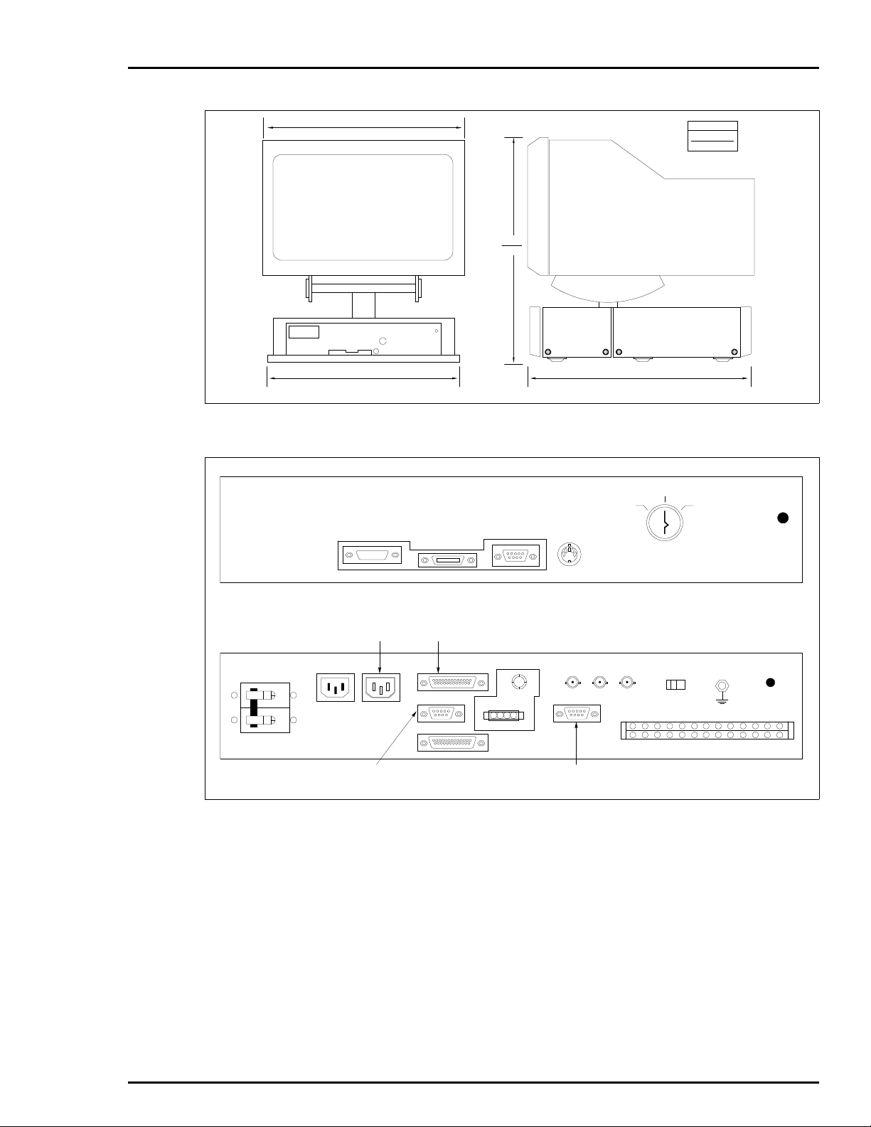
3-1. IIOIC421 Tabletop (19-inch) Dimensions................................................................ 3-7
3-2. IIOIC421 Tabletop Connections (Keyboard Interface Assembly) ..............................3-7
3-3. IIOIC421 Tabletop Cable Connections.................................................................... 3-8
3-4. IIOIC422 Console Dimensions .............................................................................3-10
3-5. IIOIC422 Console Keyboard Table........................................................................ 3-11
3-6. IIOIC422 Console 15 Degree Wedge Dimensions ..................................................3-11
3-7. IIOIC422 Console 45 Degree Wedge Dimensions ..................................................3-12
3-8. IIOIC422 Console Power Entry Panel Connections ............................................... 3-13
3-9. IIOIC422 Console Cable Connections................................................................... 3-14
3-10. IIOIC423 Environmental Cabinet Dimensions...................................................... 3-16
3-11. IIOIC423 Environmental Cabinet Anchoring Dimensions .....................................3-17
3-12. IIOIC423 Environmental Cabinet Power Entry Panel Connections ........................ 3-18
3-13. IIOIC423 Environmental Cabinet Cable Connections ........................................... 3-19
3-14. IIOIC424 Panel Mount Dimensions ...................................................................... 3-20
3-15. IIOIC424 Panel Mount Power Entry Panel Connections ........................................ 3-21
3-16. IIOIC424 Panel Mount Connections ..................................................................... 3-22
3-17. Operator Keyboard .............................................................................................. 3-23
3-18. Engineering Keyboard.......................................................................................... 3-24
3-19. IIADP01 Annunciator Display Panel SW1 Settings ............................................... 3-25
3-20. IIADP02 Annunciator Display Panel..................................................................... 3-26
3-21. NADS03 Annunciator Display Panel SW1 Settings ............................................... 3-27
3-22. Touch Screen Controller Card Connections.......................................................... 3-29
3-23. Touch Screen Switch and Jumper Settings .......................................................... 3-30
6-1. IIMKM02A Multibus Keyboard Module................................................................... 6-2
6-2. IIOIC422 Multibus Card Cage (Front View) ............................................................ 6-4
6-3. IIOIC422 Multibus Card Cage (Rear View).............................................................. 6-5
6-4. Connections to DC Distribution Board................................................................... 6-6
6-5. Power Supply Removal for IIOIC421 Tabletop Console ........................................... 6-7
6-6. Power Supply Removal for IIOIC422 Consoles ........................................................ 6-8
6-7. Power Supply Removal for IIOIC423 Environmental Console .................................. 6-9
6-8. Power Supply Removal for IIOIC424 Panel Mount Console ................................... 6-10
6-9. Power Entry Panel (PEP) Removal for IIOIC422 Consoles...................................... 6-12
6-10. Power Entry Panel (PEP) Removal for IIOIC423 Environmental Cabinet ................ 6-13
6-11. Power Entry Panel Removal for IIOIC424 Panel Mount ......................................... 6-14
6-12. ADP02 Removal from IIOIC422 Console ............................................................... 6-15
6-13. NADS03 Removal from IIOIC423 Environmental Cabinet ..................................... 6-17
6-14. Keyboard Interface Assembly (IIOIC422 Model) ....................................................6-18
6-15. Keyboard Interface Assembly Removal for IIOIC422 Consoles .............................. 6-20
6-16. Color Monitor Connections .................................................................................. 6-22
6-17. CPU Removal for IIOIC421 Tabletop Console ....................................................... 6-26
6-18. CPU Removal for IIOIC422 Consoles .................................................................... 6-27
6-19. CPU Removal for IIOIC423 Environmental Console .............................................. 6-28
6-20. CPU Removal for IIOIC424 Panel Mount Console ................................................. 6-29
6-21. CPU Connector Identification............................................................................... 6-30
A-1. IIMKM02A Multibus Keyboard Module...................................................................A-1
A-2. Keyboard Interface Connector Board...................................................................... A-2
®
vi I-E96-192-5A
Page 12

List of Figures
No. Title Page
A-3. IIOIC421 Keyboard Interface Assembly.................................................................. A-2
A-4. Color Monitor........................................................................................................ A-3
A-5. Touch Screen Controller Board ............................................................................. A-3
A-6. IIADP01, IIADP02 and NADS03 ............................................................................. A-4
A-7. IIADP01 Multiple Annunciator Displays ................................................................ A-4
(continued)
I-E96-192-5A vii
Page 13

OVERVIEW
INTENDED USER
SECTION 1 - INTRODUCTION
The IIOIC42 Operator Interface Console (auxiliary console) is a
remote monitor and keyboard interface that connects to a
main console, either a IIOIS41 or IIOIS42 Operator Interface
Station (G.3 or later software). The main console connects to
the Plant Loop
In this document, auxiliary terminal refers to an IIOIC42 console (Figures 1-1 through 1-4). Read all of this instruction to
get the greatest benefit of the information it contains. Read
each procedure before doing the task. Call the local Elsag
Bailey sales office for technical assistance.
This section contains an overview of the auxiliary console. This
document contains directions and cautions for installing and
servicing the operator interface console (OIC).
System engineers and technicians with a background in process control systems should read this instruction thoroughly
before installing and using the system. Do not put the console
into operation until you read and thoroughly understand this
instruction. This instruction is a reference for installers with
installation and maintenance experience on process control
equipment. It is not a tutorial.
®
or INFI-NET® communication highway.
OIC DESCRIPTION
The operator interface console is an auxiliary console for the
main console (OIS). It provides a remote operator interface for
displaying graphics, alarm summaries, INFI 90
®
OPEN status
and for logging, trending and process control. The auxiliary
console allows more than one operator to use a single main
console. The four models of OIC42 operator consoles are
19-inch tabletop (IIOIC421), console (IIOIC422 which has two
variations), environmental cabinet (IIOIC423), and 19-inch
panel mount model (IIOIC424). The variations of the console
model (IIOIC422) can have an upper monitor (IIOIC4222) or
lower monitor (IIOIC4221).
An Ethernet network cable connects the OIC auxiliary console
to a OIS main console. Refer to Section 3 and Section 6 for more
hardware information. Four models of the OIC are shown in
Figures 1-1, 1-2, 1-3 and 1-4. Table 1-1 lists the models.
®
Registered trademark of Elsag Bailey Process Automation.
OVERVIEW
I-E96-192-5A 1 - 1
Page 14

INTRODUCTION
MONITOR
ASSEMBLY
KEYBOARD
INTERFACE
ASSEMBLY
CPU
POWER SUPPLY
AND M KM BOARD
LOCATEDINSIDE
CASE
KEYBOARD
ASSEMBLY
Baile y
MOUSE
WORK SURFACE
ASSEMBLY
Figure 1-1. IIOIC421 Tabletop Model
®
TP80559A
ANNUNCIATOR
DISPLAY PANEL
KEYBOARD
INTE RFACE
ASSEMBLY
POWER SUPPLY
DC DISTRIBUTION
BOARD
POWER ENTRY
PANEL
REAR VIEW FRONT VIEW
MULTIBUS
CARD CAGE
CPU
ANNUNCIATOR
DISPLAY
PANEL
KEYBOARD
INTE RFACE
ASSEMBLY
KEYBOARD
POWER ENTRY
PANEL
MKM MODULE
TP80560A
Figure 1-2. IIOIC4221 Console Model
OIC DESCRIPTION
1 - 2 I-E96-192-5A
Page 15

NADS03 ANNUNCIATOR
DISPLAY (CPU
MOUNTED BEHIND IN
VERTICAL POSITION)
QWERTY
KEYBOARD
JOYSTICK
OPERATO R
KEYBOARD
ASSEMBLY
MKM MODULE
POWER ENTRY PANEL,
POWER SUPPLY AND
KEYBOARD INTERFACE
ASSEMBLY
INTRODUCTION
MONITOR
ASSEMBLY
OFF
TUNE CONFIG
KEYBOARD
AUX 1
PORT
Figure 1-3. IIOIC423 Environmental Model
SPLIT TOP
COVER C RT
POWER EN TRY
PANEL (INCLUDES
MKM MODULE AND
POWER SUPPLY)
CPU
MOUSE/
TRACKBALL
AUX
KBD
KEYBOARD INTERFACE
ASSEMBLY
TP80561A .
TP80562A
Figure 1-4. IIOIC424 Panel Mounted Model
OIC DESCRIPTION
I-E96-192-5A 1 - 3
Page 16

INTRODUCTION
CPU (Central Processing Unit)
The CPU described in this manual is a Tektronix Model XP400.
Specifications for this CPU are listed at the end of this section
and in the manufacturer’s manuals.
IIOIC421 Tabletop Console
The hardware of the tabletop console is located in a moveable
case which sits on a work surface. The power supply and multibus keyboard module (IIMKM02A, also referred to as the
MKM) are in the case. The monitor is mounted on top of the
case and the keyboard interface assembly is located below the
monitor. The monitor can tilt and swivel.
®
Table 1-1. IIOIC42 Models
Nomenclature Description
IIOIC421 Tabletop with 19-inch monitor
IIOIC4221 Console with lower monitor
IIOIC4222 Console with upper monitor
IIOIC423 Environmental cabinet
IIOIC424 Panel mounted
The rear connector panel has an AC input, alarm relays, connectors for monitor cables and a power switch. The front panel
has the connectors for peripheral operator input devices and a
tune-off-configuration keyswitch. The CPU is located inside
the table on a shelf. Access the connections from the rear of
the cabinet. The alarm relays are for alarm annunciation only.
IIOIC4221 and IIOIC4222 Console
The hardware of the OIC422 console is very similar to the OIS
console. There are several differences. The CPU has only a
multibus keyboard module, it does not have a CIU, and it does
not have a floppy disk drive or hard disk drive.
The annunciator display panel and keyboard interface assembly are located to the right of the monitor. The power entry
panel is mounted in a vertical position in the lower part of the
cabinet. The multibus card cage and MKM module are to the
left of the power entry panel. The console may have a lower
monitor or an upper monitor.
IIOIC423 Environmental Cabinet
The environmental cabinet contains a monitor, power entry
panel, operator keyboard, annunciator display panel and
interface similar to the console model, 19-inch panel mount
and 19-inch tabletop model.
OIC DESCRIPTION
1 - 4 I-E96-192-5A
Page 17

IIOIC424 Panel Mounted
INSTRUCTION CONTENT
INTRODUCTION
The hardware of the environmental OIC console is separated
into the upper and lower half of the cabinet. The CPU and
monitor are located in the top of the cabinet. The power entry
panel and MKM module are in the lower half of the cabinet
with the power supply. The annunciator display panel and
monitor are on the front of the cabinet. The alarm relays are
for alarm annunciation only.
A sealed air conditioner provides internal cooling and the
stainless steel exterior provides corrosion protection.
The hardware of the panel mounted OIC console is located
behind the monitor and keyboard interface assembly. The
power supply, power entry panel, CPU and MKM module are
located with the monitor. The keyboard interface assembly is
mounted on a separate panel. The alarm relays are for alarm
annunciation only.
Introduction
Presents an overview of the OIC consoles and related hardware. It also provides a complete list of specifications.
Description and
Operation
Installation
Describes the theory of operation of the OIC consoles and
related hardware.
Describes the installation and cabling. It also describes the
jumper settings of the multibus modules and peripherals. Be
sure to read and follow all warnings and cautions.
Troubleshooting
Lists troubleshooting steps and provides a troubleshooting
guide.
Maintenance
Component Description
and Replacement
Support Services
Quick Reference
Information
Contains a schedule and procedures for maintenance.
Describes the hardware associated with the OIC42 and
replacement procedures for that hardware.
Includes a spare parts list and ordering instructions.
Contains jumper and switch settings and fuse locations.
HOW TO USE THIS INSTRUCTION
Read this entire instruction through in sequence before
attempting to install or use the console. It is important to
become familiar with the entire content of the instruction prior
to installing and operating the console to attain maximum system efficiency.
INSTRUCTION CONTENT
I-E96-192-5A 1 - 5
Page 18

INTRODUCTION
The instruction is organized into seven sections and a quick
reference. Its organization enables finding specific information
quickly, and using this instruction as a reference after becoming fully familiar with the console.
Be sure to read the notes which provide:
•
Additional information.
•
Information that should be considered before performing a
certain operation or function.
GLOSSARY OF TERMS AND ABBREVIATIONS
Table 1-2 contains those terms and abbreviations that are
unique to Bailey or have a definition that is different from
standard industry usage.
Table 1-2. Glossary of Terms and Abbreviations
Term Definition
ADP Annunciator display pan el.
CPU Tektronix Model XP400 Logic Module
INFI-NET Advanced data communication highway.
MKM The designation MKM in this manual refers to the IIMKM02A
multibus keyboard module.
OIS Operator interface station. Integrated operator console with
data acquisition and r eporting capabilities providing a digital
access into the process for flexible control and monitoring.
PCU Process control unit. A node on the plant-wide communication
network containing control and I/O modules.
PEP Power entry panel.
Plant Loop Network 90 data communication highway.
®
REFERENCE DOCUMENTS
Table 1-3 lists Elsag Bailey instructions referenced in this
instruction.
Table 1-3. Reference Documents
Number Document
I-E96-191-4 Hardware, Operator Interface Station, IIOIS41
I-E96-192-1 Operation, Operator Interface Station (40 Series)
I-E96-192-2 Configuration, Operator Interface Station (40 Series)
I-E96-192-3 File Utilities, Operator Interface Station (40 Series)
I-E96-192-4 Hardware, Operator Interface Station, IIOIS42
I-E96-500 Site Planning and Preparation
GLOSSARY OF TERMS AND ABBREVIATIONS
1 - 6 I-E96-192-5A
Page 19

NOMENCLATURE
INTRODUCTION
Table 1-4 contains the nomenclature used in this instruction.
Table 1-4. Hardware Nomenclature
Nomenclature Description
IIAKB04 QWERTY style auxiliary (engineering) keyboard.
IIAMS04 Mouse cursor controller.
IIATB05 Trackball cursor controller.
IIMKM02A Multibus keyboard module.
IIOIC421 Tabletop operator console w ith a 19-inc h monit or, tilt/
swivel base and keyboard .
IIOIC4221 Console styl e operato r conso le with a lower mounted
19-inch monitor and ke yboard.
IIOIC4222 Console style operator console with an upper
mounted 19-inch monitor with tilt swivel base and
keyboard.
IIOIC423 Environmental operator console with a 19-inch moni-
tor and keyboard.
IIOIC424 Panel mount operato r console with a 19-in ch monit or
and engineering keyboard.
OIC CONSOLE SPECIFICATIONS
Table 1-5 contains the specifications for the OIC Console.
Table 1-5. OIC Console Specifications
Property Characteristic/Value
Power
Line voltage
Line frequency
Circuit breaker size
Power characteristics
240 V nominal (180 VAC to 264 VAC RMS)
120 V nominal (90 VAC to 132 VAC RMS)
47 to 63 Hz
20 A circuit breaker for IIOIC422 and IIOIC423 consoles
10 A circuit breaker for IIOIC421 and IIOIC424 consoles
Model
IIOIC421 42 2.96 0.610
IIOIC4221 42 2.34 0.730
IIOIC4222 42 2.34 0.730
IIOIC423 42 1.95 0.843
IIOIC424 42 2.96 0.610
Inrush Current
Amps Typical
Crest Factor
Power Factor
Typical
NOMENCLATURE
I-E96-192-5A 1 - 7
Page 20

INTRODUCTION
®
Table 1-5. OIC Console Specifications
(continued)
Property Characteristic/Value
Power consumption
Model Voltage
IIOIC421 120 1.96 2.55 175 227
240 1.20 1.56 175 227
IIOIC4221 120 1.80 2.34 158 205
240 1.11 1.44 162 211
IIOIC4222 120 1.80 2.34 158 205
240 1.11 1.44 162 211
IIOIC423 120 3.95 5.14 401 521
240 1.93 2.51 392 510
IIOIC424 120 1.96 2.55 175 227
240 1.20 1.56 175 227
Typical
Amps
Maximum
Amps
Power supply +5 VDC at 20 A, +12 VDC at 4 A, -12 VDC at 4 A
Keyboard Interface
Operator keyboard output relays rated at 250 mA 24-28 VDC per IIMKM02A
module.
Alarm Relays Rating
Contact Voltage 24 VDC
Contact Current 0.25 A
Contact Power 6 W
Typical
Watts
Maximum
Watts
Alarm relays
Alarm tones
6 per keyboard
5 per keyboard
Keyboards 1 Mylar (operator)
1 Engineering (QWERTY)
Annunciator display
4 (per IIMKM02A module) 32 pushbuttons and LEDs per panel
panels
Environment
Temperature
Operating: 10° to 40°C (50° to 104°F)
Nonoperating
1
: -30° to 65°C (-22° to 149°F
Storage: 5° to 50°C (41° to 122°F)
Relative humidity
Operating: 20% to 80% noncondensing
Recommended minimum: 40%
Storage: 10% to 90% noncondensing
Altitude
-0.3 to +2.4 km (-0.2 to 1.5 mi)
Cooling requirements
(Heat dissipation)
Model
IIOIC421 598 775
IIOIC4221 540 700
IIOIC4222 540 700
IIOIC423 1,339 1,742
BTU/Hr
Nominal
IIOIC424
BTU/Hr
Maximum
598 775
OIC CONSOLE SPECIFICATIONS
1 - 8 I-E96-192-5A
Page 21

INTRODUCTION
Table 1-5. OIC Console Specifications
(continued)
Property Characteristic/Value
Dimensions
Model
IIOIC421 55.80 22.00 49.53 19.50 60.96 24.00
IIOIC4221 107.27 42.23 71.12 28.00 109.01 42.92
IIOIC4222 156.94 61.78 71.12 28.00 109.01 42.92
IIOIC423 177.8 70.00 76.20 30.00 95.09 37.45
IIOIC424 614.1 24.17 116.00 45.67 94.97 37.39
Height Width Depth
cm. in. cm. in. cm. in.
Weight
Model
IIOIC421 175 386
IIOIC4221 164 360
IIOIC4222 191 420
IIOIC423 240 530
IIOIC424 71 157
Weight
kg lbs
Electrical noise Keep cabinet doors closed. Do not use portable transmitting equipment
within 2 m (6.5 ft) of a cabinet.
Certification (pending) CSA certified for use in an ordinary (non haz ard ous ) co ntro ll ed en vi ronm en t.
NOTE :
Nonoperating environment is defined as a transportation or storage period of less than 60 days.
1.
SPECIFICATIONS SUBJECT TO CHANGE WITHOUT NOTICE
OIC CONSOLE SPECIFICATIONS
I-E96-192-5A 1 - 9
Page 22

INTRODUCTION
SECTION 2 - DESCRIPTION AND OPERATION
This section explains the theory of operation for the operator
interface console. An operator uses the OIC console to monitor
and control the process through an OIS main console. For OIC
operating procedures, refer to the operation instruction.
The OIC console interfaces to INFI-NET and Plant Loop communication highways through the OIS main console. It can
monitor and allow manual control of a process through color
graphics displays which show equipment status and process
state. Figure 2-1 shows a block diagram of the communication
process.
DECNET
IIOIC421
IIOIS42
IIOIC422
IIOIC423
IIOIC424
COMMUNICATION HIGHWAY (INFI-NET OR PLANT LOOP)
COMMUNICATION
MODULES
CONTROL
MODULE
IIOIS20
CONTROLWAY
I/O EXPANDE R B U S
CONTROL
MODULE
Figure 2-1. OIC Communication Levels
IIOIC201
IIOIC202
IIOIC203
IIOIC204
IIOIC205
TP36271B
INTRODUCTION
I-E96-192-5A 2 - 1
Page 23

DESCRIPTION AND OPERATION
OIC CONSOLE FUNCTIONAL OPERATION
The OIC console controls and monitors a process through the
OIS console. The OIC console is a remote operator station with
a monitor and keyboard controlled by a CPU. Commands
between the OIC and OIS main console pass through an Ethernet network cable using either DECnet or TCP/IP protocol.
The OIC console uses a Tektronix model XP400 terminal logic
module. In the OIC console, the CPU sends video signals to the
monitor. A cable connects the CPU to the RGB connectors on
the monitor.
Figure 2-2 is a block diagram of the IIOIC42 operator interface
console. Refer to Section 3 for OIC CPU connections. Refer to
Section 6 for a description of the CPU.
INFI 90 O PEN
OPERATOR
KEYBOARD
®
IIAKB04
ENGINEERING
KEYBOARD
TOUCH SCREEN
JOYSTICK
(IIOIC423 ON LY)
KEYBOARD
INTER FACE
PANEL
MOUSE/
TRACKBALL
(IIOIC423 ON LY)
IIMKM02A
KEYBOARD
MODULE
CPU
RGB
MONITOR
ETHERNET
Figure 2-2. IIOIC42 Block Diagram
MOUSE/
TRACKBALL
(NOT USED ON
IIOIC423)
ADP PANEL
NETWORK
TO IIOI S 4 2
TP36273B
OIC CONSOLE FUNCTIONAL OPERATION
2 - 2 I-E96-192-5A
Page 24

INTRODUCTION
SPECIAL HANDLING
SECTION 3 - INSTALLATION
This section explains how to install and prepare the OIC consoles. This section is a guide for the system engineer or technician. Follow the procedures in this instruction carefully to
install, maintain and use the system properly. Elsag Bailey
recommends reading the entire instruction before beginning
the installation and powering up the console.
For other installation information, refer to the Site Planning
and Preparation instruction and the appropriate OIS instruction. Refer to Table 1-3 for the instruction number.
Observe these steps when handling electronic circuitry:
NOTE:
19483851) consisting of two wrist straps, ground cord assembly,
alligator clip, and static dissipating work surface when working with
static sensitive devices. The kit is designed to connect the technician and the static dissipating work surface to the same ground
point to prevent damage to the static sensitive devices by electrostatic discharge.
Always use the Elsag Bailey Field Static Kit (part number
Use the static grounding wrist strap when installing and
removing modules. Static discharge may damage static sensitive devices on modules in the cabinet. Use grounded equipment and static safe practices when working with static
sensitive devices.
1. Use static shielding bag. Keep the modules in static
shielding bag until you are ready to install them in the system.
Save the bag for future use.
2. Ground bags before opening. Before opening a bag containing an assembly with static sensitive devices, touch it to
the equipment housing or ground to equalize charges.
3. Avoid touching circuitry. Handle assemblies by the
edges; avoid touching the circuitry.
4. Avoid partial connection of static sensitive devices.
Verify that all devices connected to the modules are properly
grounded before using them.
5. Ground test equipment.
INTRODUCTION
I-E96-192-5A 3 - 1
Page 25

INSTALLATION
6. Use An Antistatic Field Service Vacuum. Remove dust
from the cards if necessary.
7. Use a grounded wrist strap. Connect the wrist strap to
the appropriate grounding plug on the power entry panel. The
grounding plug on the power entry panel is connected to the
cabinet chassis ground.
8. Do not use lead pencils to set dipswitches. To avoid
contamination of switch contacts that can result in circuit
board malfunction, do not use a lead pencil to set a dipswitch.
UNPACKING AND INSPECTION
Follow these steps for general handling:
1. Examine the console to make sure that no damage has
occurred in transit.
2. Notify the nearest Elsag Bailey sales office of any damage.
®
WARNING
AVERTISSEMENT
3. File a claim for any damage with the shipping company
that handled the shipment.
4. Use the original packing material or container to store the
console.
5. Store the console in a place with clean air; free of extremes
of temperature and humidity. Refer to Section 1 for the console
specifications.
Verify all covers are installed and all doors are closed before
operating the console. Exposed electrical connections present
a shock hazard that can cause injury or death.
Assurez-vous que tous les couvercles sont installés et toutes
les portes fermées avant de faire fonctionner la console.
L´exposition à des connexions électriques presénte un risque
de blessure ou d´électrocution fatale.
Do not remove or install circuit boards with power applied to
the console. The circuit board may be damaged. Remove power
to all AC wiring when removing or connecting AC wires to prevent personal injury and equipment damage. Remove DC
power to all DC wiring when removing or connecting DC wires
or circuit boards to prevent personal injury and equipment
damage.
UNPACKING AND INSPECTION
3 - 2 I-E96-192-5A
Page 26

INSTALLATION PROCEDURE
The following steps outline the required procedure to complete
the installation of the OIC console. Follow all related safety
procedures when doing these steps.
INSTALLATION
NOTE:
multibus card cage or doing maintenance on equipment containing
static sens itive devices, read
Before removing the multibus keyboard module from the
SPECIAL HANDLING
.
1. Install the cabinet or panel. Refer to the dimension drawings and instructions in the installation and setup sections
found later in this section.
2. Vibration during shipping and handling may unseat the
multibus keyboard module and connections, causing problems. Verify that the module is seated and that all terminal
block screws and stud fasteners are tight.
3. Refer to IIMKM02A MULTIBUS KEYBOARD MODULE in
Section 6 to check the jumper settings.
4. Connect OIC consoles to the OIS. Refer to the installation
and setup procedure for the OIC model being installed.
5. Verify that no power is present to the OIC when making
power wiring connections. Wire AC power according to the procedures in OIC INSTALLATION. Refer to the Site Planning
and Preparation instruction, the power requirements in
Section 1 and AC POWER WIRING GUIDELINES in this section.
NOTES:
1. Verify that the incoming voltage meets the rating on the label of
TB1 on the power entry panel and Table 1-5.
2. Make certain the OICs being installed are powered using the
same power source and ground as the OIS consol e. Failure to do so
may cause improper operation.
6. After completing the wiring:
•
Check that the keyboards and printers are connected to
the correct port. Refer to the appropriate wiring connections and cabling section and PERIPHERALS.
•
Ethernet network cable requires a terminator at each end
of the cable.
•
Check the AC voltage sources for proper voltage and current values. Refer to the specifications in Section 1 and AC
test in Section 4.
•
Apply power. If problems occur, refer to Section 4 for troubleshooting information.
INSTALLATION PROCEDURE
I-E96-192-5A 3 - 3
Page 27

INSTALLATION
AC POWER WIRING GUIDELINES
Make sure that all voltage labels and voltage switch settings on
the peripheral devices, power supply and power entry panel
CAUTION
ATTENTION
show the correct operating voltage. Equipment damage may
result if the incorrect voltage is connected. Make sure the console main power circuit breaker is off before changing operating voltage setting or equipment damage may result.
Assurez-vous que toutes les indications de tension et tous les
réglages de tension sur les périphériques, l e bloc d´alimentation et le panneau d´entrée des alimentations correspondent
bien à la tension de service. Une tension incorrecte risque
d´endommager l´equipment. Assures-vous que le disjoncteur
d´alimentation principal de la console est étient avant de modifier les réglages de tension de service afin d´éviter d´endommager l´équipment.
IIOIC422 AC power input connects to a terminal block on the
power entry panel. The power entry panel location and part
number will vary according the IIOIC42 model selected. The
IIOIC421 (tabletop model) does not use the power entry panel.
It has a rear connector panel with an IEC style AC input on the
keyboard interface assembly. Refer to the following sections
under OIC INSTALLATION for detailed AC power wiring connection procedures. The operator interface console can operate from 120/240 VAC, 50/60 hertz. The power entry panel
provides line filtering, transient suppression and a 20-amp circuit breaker.
®
Setting up the IIOIC42 console for 240 VAC requires no
changes. The power supply is autosensing. Refer to Section 6
for more power supply information. The color monitor is
autosensing and needs no changes for 240-VAC operation.
Monitors by other vendors may require changes. The CPU is
also autosensing and needs no change for 240-VAC operation.
The recommended minimum size for power wiring is 14 AWG
copper wire with a 600 volt, 75-degrees Celsius (167-degrees
Fahrenheit) rating and thermoplastic insulation. Wire with a
300-volt or 150-volt rating may be used if it is accepted by
local wiring codes. Wiring must be protected by cable trays or
conduit and suited for the service voltage.
Power wiring to the OIC console must include a third-wire
grounding conductor. This grounding conductor must not be a
smaller gauge than the power wiring and must be either bare,
green colored or green/yellow colored if insulated. The grounding conductor must be terminated at the system safety ground
connection on the front of the power entry panel.
AC POWER WIRING GUIDELINES
3 - 4 I-E96-192-5A
Page 28

AC OUTLETS
CAUTION
ATTENTION
INSTALLATION
Over-current protection provided for the AC distribution must
be sized to allow for the inrush current required by the OIC
hardware. Refer to the specifications in Section 1 for the peak
inrush current and duration for the OIC console.
For more information on power wiring, grounding, line conditioning and EMI (electromagnetic interference), refer to the
Site Planning and Preparation instruction.
Remove power from all equipment and the console before
installing or removing peripheral equipment. Equipment damage may result.
Coupez l´alimentation des périphériques et de la console avant
d´installer ou de retirer des périphériques, sinon l´équipment
risque de subir des dommages.
The number of AC outlets varies according to the OIC42 model
being used.
OIC INSTALLATION
NOTE:
outlets. Electrical noise may cause data to be lost or changed.
Do not connect motors, lights or test equipment to the AC
This section contains the installation and setup instructions
for the IIOIC421 tabletop, IIOIC422 console, IIOIC423 environmental cabinet and IIOIC424 panel mounted auxiliary terminals. Follow all cautions and warnings.
The OIC console is internally wired when it is shipped. Connect the communication loop cables, AC power and any
peripheral devices. Peripheral devices connect to the front of
the power entry panel, or to the keyboard interface assembly
front panel (IIOIC421 tabletop). Table 3-1 contains the color
codes for the wiring in the OIC console.
Table 3-1. OIC Wiring Color Codes
Color Function
Brown AC hot (inside PEP chassis only)
Blue AC neutral
Green/Yellow AC common
Brown +5 VDC
White/Green DC common
Violet -12 VDC
White/Violet +12 VDC
AC OUTLETS
I-E96-192-5A 3 - 5
Page 29

INSTALLATION
®
Table 3-1. OIC Wiring Color Codes
Green -Remote voltage sense signal wire
White +Remote voltage sense signal wire
Follow local wiring codes when wiring and installing cableways
or conduit. For more information, refer to the Site Planning
and Preparation instruction.
IIOIC421 Tabletop Installation and Setup
Verify all covers are installed and all doors are closed before
WARNING
operating the console. Exposed electrical connections present
a shock hazard that can cause injury or death.
Assurez-vous que tous les couvercles sont installés et toutes
AVERTISSEMENT
les portes fermées avant de faire fonctionner la console.
L´exposition à des connexions électriques presénte un risque
de blessure ou d´électrocution fatale.
The IIOIC421 tabletop model is normally used with a floor
mounted cabinet. The descriptions and procedures in this section apply only to the tabletop unit and do not apply to the
cabinet. Figure 3-1 shows the dimensions of the OIC tabletop
model.
(continued)
Color Function
IOIC421 Tabletop Wiring Connections and Cabling
The IIOIC421 tabletop operator interface console is internally
wired when it is shipped. Connect the AC power and any peripheral devices. AC power input connects to the power connector on
the rear of the keyboard interface assembly (Figure 3-2).
Figure 3-3 shows cabling requirements. The circled numbers
illustrate the cables. Those numbers are called out in Table 3-2
which contains a description of the cabling connections.
OIC INSTALLATION
3 - 6 I-E96-192-5A
Page 30
INSTALLATION
TP80546A.
Baile y
495.3
19.5
609.6
24.0
482.6
19.0
558.8
22.0
Figure 3-1. IIOIC421 Tabletop (19-inch) Dimensions
OFF
TUNE CO NFIG
KEYBOARD
AUX 1
PORT
MOUSE/
TRACKBALL
AUX
KBD
DIMENSIONS
MILLIMETERS
INCH ES
TP35324B
POWER
TO
CPU
AC IN AC OUT
TO
COMMUNICATION
PORT
J1
J2 J3
J4
R G B RESET DEGAUSS
F1
2
4
2
2
NC
NO
4
4
NC
CO
CO
NO
6
NO
WRIST
STRAP
6
NC
6CODI
DI
2+
2–
J5
1
3
5
3
5
5
DI
NC
CO
NO
DI
NC
1+
1–
CO
TO KEYBOARD
PORT
TO MOU S E
PORT
1
1
3
NC
CO
NO
NO
Figure 3-2. IIOIC421 Tabletop Connections (Keyboard Interface Assembly)
DO
DO
2+
2–
DO
DO
1+
1–
OIC INSTALLATION
I-E96-192-5A 3 - 7
Page 31

INSTALLATION
®
IIOIC42 1
CHASSIS
FAN
9
P2
POWER
SUPPLY
P3
P1
10
J4AC O UT AC IN
TO AC PO W E R
9
11
10
RESET
SWITCH
MONITOR
AC IN
RGB
18
POWER CABLE
DEGAUSS
VIDEO CABLE
17
OPERATOR KEYBOARD MOUSE/TRACKBALL
OPTIONAL TABLETOP
ADP PANEL
9
12
6
BRIGHTNESS
CONTRAST
MONITOR
7
BEZEL
KEYBOARD
CPU
MONITOR
POWE R
AC IN
AUX
PORT
P2
P10
0PORT
MOUSE
1PORT
KEY-
BOARD
KEYBOARD
INTERFACE
BOARD
P4
IIMKM02A
KEYBOARD
P16
MODULE
P3
TERM
ETHERNET
NETWORK CABLE
(CUSTOMER
SUPPLIED)
MOUSE/
TRACK-
BALL
P6 P9
BLK
2
1
15
13
3
ENGINEERING
KEYBOARD
AUX
KBD
P8
P1
P5
P7
P8
8 14
J1
TO IIOIS41/42
4
TOUCH
SCREEN
12
J3 J5J2
= SIGNAL CABLE
5
16
TP80565A
Figure 3-3. IIOIC421 Tabletop Cable Connections
Table 3-2. IIOIC421 Tabletop Cable Connections
Figure 3-3
Cable No.
1 6642339A1 Keyboard J2 on chassis Keyboard port on OIC CPU
2 6640778A1 Communication J1 on chassis 0 port on OIC CPU
3 6634512A26N15 ADP signal P6 on IIMKM02A Terminal block on chassis
4 6634512A26N15 I/O distribution P5 on IIMKM02A P1 on keyboard interface board
5 6634512A26N15 I/O distribution P7 on IIMKM02A P8 on keyboard interface board
6 6638719A2 Reset cable P4 on IIMKM02A Reset switch on power entry panel
7 6638720A6 Monitor bezel
8 6639117A1 I/O signal P9 on IIMKM02A J1 on chassis (inside)
9 6639211A1 Power P2 on power supply Cooling fan
Cable Number Cable Name Connect From Connect To
Degauss on chassis Brightness on bezel
controls
contrast on bezel monitor
P2 on keyboard interface board
P16 on IIMKM02A
OIC INSTALLATION
3 - 8 I-E96-192-5A
Page 32

INSTALLATION
Table 3-2. IIOIC421 Tabletop Cable Connections
Figure 3-3
Cable No.
10 6639212A1 AC power Power in on chassis P1on power supply
11 6639213A1 PFI sense P3 on IIMKM02A P3 on power supply
12 6639637A1 Keyboard data P10 on keyboard
13 6640778A2 Touch screen J5 on chassis 1 port on the OIC CPU
14 6640857A1 Keyboard signal P8 on IIMKM02A J2 on chassis (inside)
15 6642341A1 Mouse J3 on chassis Mouse port on OIC CPU
16 6642342A1 Touch screen Touch screen board J5 on chassis
17 Power cable Power AC IN on OIC CPU AC OUT on chassis
18 1949448A1 Video (RGB) Monitor port on
Cable Number Cable Name Connect From Connect To
interface board
OIC CPU
(continued)
AC IN on chassis
J3 on chassis (inside)
RGB on table top chassis
IIOIC422 Console Setup and Installation
The OIC and OIS consoles are similar, except the OIC console
has no floppy disk drives or network interface unit. The cabinet size and installation are the same. Figure 3-4 shows the
dimensions.
Before the OIC console cabinet is set into place in a control
room, insure that the floor is level in the area where the cabinets will be set. Make sure the location can accommodate the
console. Figure 3-4 shows the console cabinet and anchoring
dimensions.
Adjust the leveling screws on all cabinets and connecting
tables until the monitor bezel of each cabinet lines up. The leveling screws adjust 25.6 millimeters (1.05 inches). After securing the cabinets, put the tables on the cabinets and lock them
into place by sliding the red handle above the front access door
to the right until it stops at the bottom of the slot.
The tabletops are adjustable. The brackets supporting the
tabletops are bolted through oversize holes. Loosen the bolts
and move the top up to 6.35 millimeters (0.25 inches) up,
down, forward or back toward the cabinet to line up the tabletop.
Two chrome table alignment pins shipped inside the brass
bushings located on each side of each tabletop. When two
tabletops are lined up, push the pins outward into the bushing
of the table to the right of the cabinet. Tighten the three bolts
on each tabletop support bracket. Figure 3-5 shows the keyboard table. Figure 3-6 shows the 15 degree wedge table
dimensions, and Figure 3-7 shows the 45 degree wedge table
dimensions.
OIC INSTALLATION
I-E96-192-5A 3 - 9
Page 33

INSTALLATION
724.6
28.527
471.8
18.575
1085.7
42.75
2
1568.3
61.74
®
1
281.8
11.09
1090.1
42.918
482.6
19.00
STUD
CENTER
830.4
32.693
66.0
2.60
TO REAR
DOOR
DIMENSIONS
MILLIMETERS
INCHES
108.7
4.28
Figure 3-4. IIOIC422 Console Dimensions
Protect the wires and cabling going to the OIC console. Run
cabling through conduit to the rear of the cabinet or under the
floor through the bottom of the cabinet. Follow local wiring
codes when wiring and installing cableways or conduit. Refer
to the Site Planning and Preparation instruction for more
information.
493.8
19.44
STUD CENTER
MOUNTING
1
HIGH MONITOR
2
LOW MONITO R
711.2
28.00
MODEL
IIOIC4222
IIOIC4221
108.7
4.28
TP80547A
OIC INSTALLATION
3 - 10 I-E96-192-5A
Page 34

INSTALLATION
RIGHT BUSHING
LEFT BRACKET
LEFT BUSHING
ADJUSTABLE MO U N TING BOLTS
(3 PER BRACKET)
PIN (ONE PER BUSHING)
6.35
0.25
6.35
0.25
6.35
0.25
Figure 3-5. IIOIC422 Console Keyboard Table
RIGHTBRACKET
TABLE SUPPORT
BRACKET
RIGHTBUSHING
DIMENSIONS
MILLIMETERS
INCHES
TP35437B
493.8
19.44
335.3
13.20
404.1
15.91
50.8
2.00
IICP I0 1
482.6
19.00
52.8
2.08
69.3
2.73
Figure 3-6. IIOIC422 Console 15 Degree Wedge Dimensions
493.8
19.44
DIMENSIONS
MILLIMETERS
INCHES
TP35319B
OIC INSTALLATION
I-E96-192-5A 3 - 11
Page 35

INSTALLATION
®
482.6
19.00
395.7
15.58
885.2
34.85
956.6
37.66
791.5
31.16
254.5
10.02
615.4
24.23
50.8
2.00
493.8
19.44
IICPI02
482.6
19.00
DIMENSIONS
MILLIMETERS
INCHES
TP35320B
1089.7
42.90
Figure 3-7. IIOIC422 Console 45 Degree Wedge Dimensions
IIOIC422 Console Wiring Connections and Cabling
The IIOIC422 console is internally wired when it is shipped.
Connect the AC power and any peripheral devices. Refer to
Section 6 for specific instructions on installing and configuring
replacement components.
1. Wire AC power to the proper terminals of the power entry
panel. Refer to Figure 3-8 for AC input terminal location.
NOTE:
of TB1.
Verify that the incoming vo ltage me ets the rati ng on the labe l
2. Connect only 120/240 VAC at 50/60 hertz into the terminal block on the power entry panel.
Figure 3-9 shows the IIOIC422 cable connections. The circled
numbers represent the cables. Table 3-3 contains the list of
those cables and connection descriptions.
NOTE:
sure they are powered using the same power source and ground as
the OIS and OIC console to reduce the chance of communication
problems on the network. Failure to do so may cause data to be
changed or lost.
If remote monitors are being install ed in the OIC console, be
OIC INSTALLATION
3 - 12 I-E96-192-5A
Page 36

REAR VIEW
NOTICE: CO NNECT POWER CORD
BEFORE CONN ECTING SIGN AL CAB LE
2
NO
NO
NC
COM
4
2
2
6
4
4
NO
NC
COM
INSTALLATION
U. DEGAUSS
L.DEGAUSS
R
E
S
E
T
6
6
DI
DO
DI
NC
COM
2+
DO
2+
2–
2–
NOT
USED
UPPER CRT
LOWER CRT
POWER SUPPLY
BLOWER/AUX
1
1
1
NO
NC
COM
POWER
ON ON
MAIN P OWE R - ON/OFF
E1
3
NO
5
3
NC
3
COM
5
NO
NC
5
COM
PERIPHERAL POWE R
NOTICE: CONNECT PERIPHERAL
RIBBON CA BLE BEFORE PLUGGING
AND POWERING UNIT.
LN/L2
WARNING/AVERTISSEMENT 120/240V
DI
1+
DO
DI
1+
1–
WRISTSTRAP
Figure 3-8. IIOIC422 Console Power Entry Panel Connections
DO
1–
TP80548A.
OIC INSTALLATION
I-E96-192-5A 3 - 13
Page 37

INSTALLATION
TERM
19
BLK
TERM
8
BLK
17
P5
TB2 P6
BACKP LANE
POW ER
SUPPLY
P2
20 21
P7 P8
DC DISTR.
BOAR D
P5
P6 P4
P3
P1
FANFAN
OPERATOR KEYBOARD MOUSE/TRACKBALL
OPTIONAL TABLETOP
P9
1018
P1
P2
ANNUNCIATO R
DISPLAY
PANE L ( A DP)
16
6
ADP PANEL
9
14
AUX
PORT
P2
P8
P7
KEYBO ARD
RESET
AC OUT
J1
POWER
AC IN
MOUSE/
KEY-
TRACK-
BOARD
KEYB OARD
IN TE R FA CE
BOA RD
IIMKM02A
MODULE
P6P4P3
11
5
TERM
BLK
IIOIC4 22
PEP
BALL
AUX
KBD
P5
P8
P9
AC O UT
AC OUT
DEGAUSS
ENGINEERING
KEYBOARD
P10
P1
J3
J2
4
3
2
1
15
MOUSE 1 PORT
KEYBOARD
POW ER
CABLE
CPU
2423
VIDEO
CABLE
0PORT
AC IN
AUX OUT MO NITOR
TOUCH
SCREEN
22
ETHERNET
NETWORK
CUSTOMER
SUPPLIED
TO IIOIS41/42
CONSOLE
®
TO AC
POWER
CUSTOMER SUPPLIED
=SIGNALCABLE
MONITOR
BEZEL
BRIGHTNESS
CONTRAST
12
13
AC LINE
MONITOR
RGB
TP80566A.
Figure 3-9. IIOIC422 Console Cable Connections
Table 3-3. IIOIC422 Console Cable Connections
Figure 3-9
Item No.
1 1947950A5 AC power J3 on power entry
2 6639637A4 I/O signal P9 on IIMKM02A 0 port on OIC CPU
3 6642339A1 Keyboard P8 on IIMKM02A Keyboard port on OIC CPU
4 6634512A26N72 I/O distribution P5 on IIMKM02A P1 on keyboard interface board
5 6634512A26N72 I/O distribution P6 on IIMKM02A Rear of terminal block on power
6 6637599A1 AC power J1 AC OUT on power
7 6637776A2 Wrist ground User Wrist connector on power entry
8 6638708A1 DC power TB2 on backplane Terminal block on DC distribution
9 6638713A1 Peripheral power P2 on keyboard inter-
Cable Number Cable Name Connect From Connect To
AC IN on OIC CPU
panel
entry panel
P1 on power supply
entry panel
panel
board
P3 on DC distribution board
face board
OIC INSTALLATION
3 - 14 I-E96-192-5A
Page 38
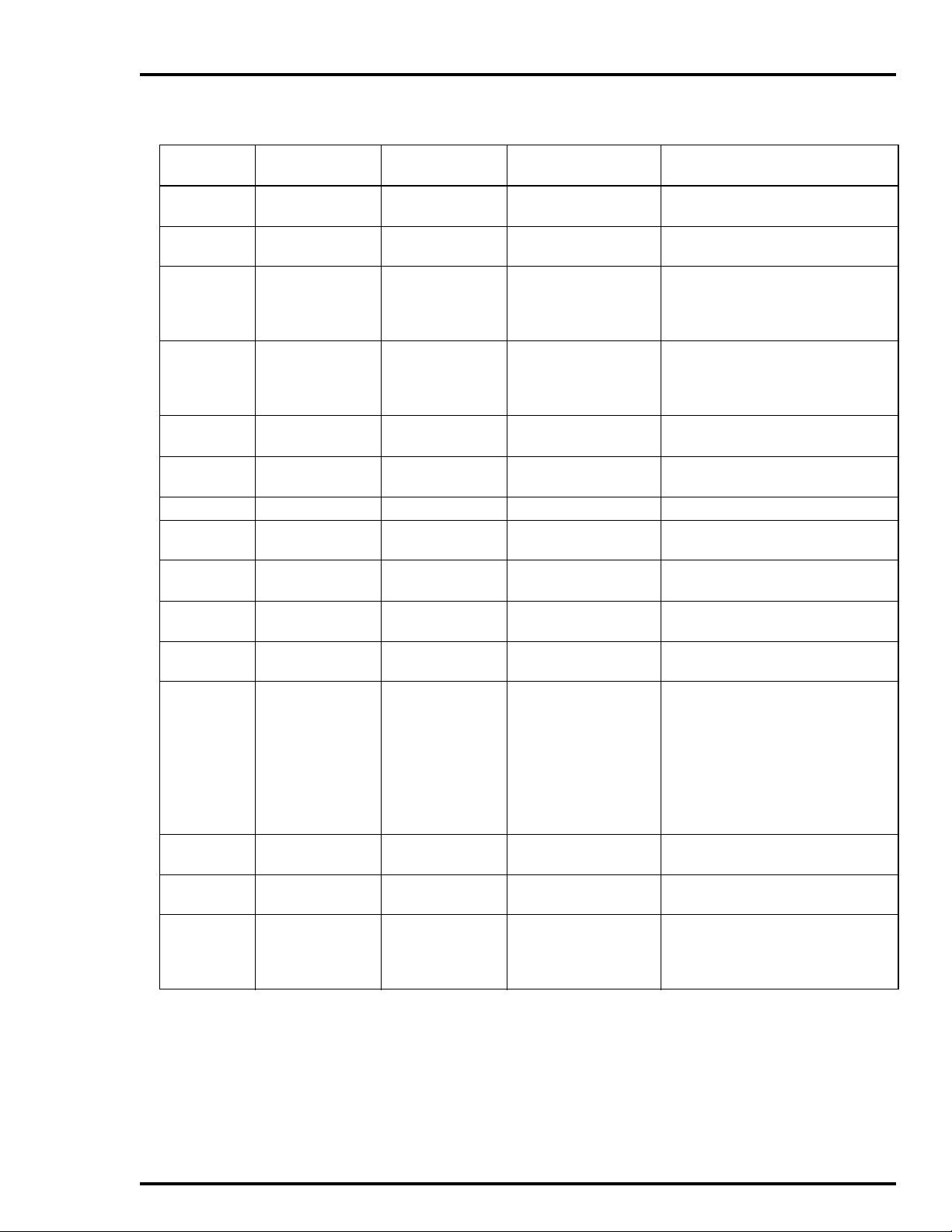
INSTALLATION
Table 3-3. IIOIC422 Console Cable Connections
Figure 3-9
Item No.
10 6638713A2 or
11 6638719A1 Reset cable Reset switch on power
12 6638720A4 Lower monitor
13 6638720A5 Upper monitor
14 6638849A1 ADP signal P7 on IIMKM02A P8 on keyboard interface board
15 6642341A1 Mouse signal P10 on keyboard inter-
16 6640113A4 PFI sense P3 on power supply P3 on IIMKM02A
17 6640368A1 Power P5 on DC
18 6640368A1 Power P6 on DC
19 6640369A1 DC power P2 on power supply Terminal block on DC distribution
20 6640640A2 DC Power P7 on DC
21 6640640A3 DC Power P8 on DC
22 6640778A2 Touch screen Connector on touch
23 Power cable AC power AC power out (AUX
24 1949448A1
Cable Number Cable Name Connect From Connect To
Peripheral power P1 on ADP board con-
6639106A1
bright
bright
Video (RGB) Monitor port on OIC
(IIOIC4221)
1949448A2
(IIOIC4222)
troller
entry panel
9-pin connector on re ar
of monitor
9-pin connector on re ar
of monitor
face board
distribution board
distribution board
distribution board
distribution board
screen board
OUTLET) on OIC CPU
CPU
(continued)
P4 on DC distribution board
P4 on IIMKM02A
Monitor bezel brightness and
monitor bezel contrast and
degaussing switch on power entry
panel
Monitor bezel brightness and
monitor bezel contrast and
degaussing switch on power entry
panel
P2 on ADP panel
Mouse port on OIC CPU
P5 on backplane
P6 on backplane
board
IIOIC4221 and IIOIC4222
Cable P2 to fan on card cage
IIOIC4221
Cable P2 to fan on lower monitor
Cable P3 to fan on lower monitor
Cable P4 to fan on lower monitor
IIOIC4222
Cable P2 to fan on lower monitor
Cable P3 to fan on lower monitor
Cable P4 not used
1 port on OIC CPU
AC power connector on
monitor
RGB on monitor
OIC INSTALLATION
I-E96-192-5A 3 - 15
Page 39

INSTALLATION
IIOIC423 Environmental Setup and Installation
Before the OIC environmental console is set into place, insure
that the floor is level in the installation area. The unit must be
secured to the floor before it is wired or operated. Figure 3-10
shows the cabinet dimensions. The dimensions for the mounting bolts are shown in Figure 3-11.
®
NOTE:
The IIOIC423 console has a built-in air conditioner that pro-
duces condensate. Install a drain to accommodate the water.
Protect the wires and cabling going to the OIC environmental
cabinet. Run cabling through conduit to the bottom of the cabinet. Follow local wiring codes when wiring and installing
cableways or conduit. Refer to the Site Planning and Prepa-
ration instruction for more information.
NOTE:
The power entry panel has a connector for AC
input and alarm relay outputs (24 VDC) and cable connectors for peripheral devices. The alarm relay outputs
are for alarm annunciation only.
EYEBOLT
REMOVABLE
762.0
30.00
96.9
3.82
777.9
1778.0
70.00
CONDUIT AND CABLE
ENTRY AREA
FRONT VIEW TOP VIEW
DIMENSIONS
MILLIMETERS
INCHES
30.63
381.0
15.0
TP35454B
Figure 3-10. IIOIC423 Environmental Cabinet Dimensions
OIC INSTALLATION
3 - 16 I-E96-192-5A
Page 40

472.5
35B
18.60
AIR
FILTER
INSTALLATION
430.3
16.94
DIMENSIONS
MILLIMETERS
INCHES
711.2
28.00
MTG CTRS
SPLASH GUARDS
12.7
0.50
DIA MTG BOLTS
4REQUIRED
Figure 3-11. IIOIC423 Environmental Cabinet Anchoring Dimensions
IIOIC423 Environmental Wiring Connections and Cabling
The IIOIC423 operator interface console is internally wired
when it is shipped. Connect the AC power and any peripheral
devices. The power entry panel provides line filtering, transient
suppression and a 20-amp circuit breaker.
1. Wire AC power to the proper terminals of the power entry
panel. Refer to Figure 3-12 for AC input terminal location.
NOTE:
of TB1. Connect only 120/240 VAC at 50/60 hertz into the terminal
block on the power entry panel.
Verify that the incoming vo ltage me ets the rating on the label
707.4
27.85
MTG CTRS
TP355
2. Connect only 120/240 VAC at 50/60 hertz into the terminal block on the power entry panel.
3. Make certain the 120/240 VAC switch is in the proper
position.
Table 3-4 has a list of circled cables and a description of the
cable connections. The cable connections are shown in Figure
3-13. Circled numbers represent the cables.
OIC INSTALLATION
I-E96-192-5A 3 - 17
Page 41

INSTALLATION
OFF
TUNE CONFIG
KEYBOARD
AUX 1
PORT
RESET
MOUSE/
TRACKBALL
DEGAUSS
AUX
KBD
®
CONTRASTBRIGHTNESS
WARNING!!
120/240 VAC
WRIST
STRAP
MAY CAUSE SEVERE
DAMAGE! SWITCH
MUST BET SET FOR
PROPER VO LTAGE!!
MAIN POWER
LN/L2
MAIN
POWER
CRT
120/240
LIGHT
120 V
TERMINAL
MAY CAUSE SEVERE
E1
AIR CONDITIONING
120/240
A/C
120 V
WARNING!!
DAMAGE!!
ONLY!
RELAY ALARM CONTACTS AC POWER INPUT C USTOMER GRO UND
CHASSIS GRO UND
TP35329B .
Figure 3-12. IIOIC423 Environmental Cabinet Power Entry Panel Connections
Table 3-4. IIOIC423 Cable Connections
Figure 3-13
Item No.
1 1947950A5 Power J2 on power entry
2 6639637A4 Communication P9 on IIMKM02A 0 port on OIC CPU
3 6642339A1 Keyboard P8 on IIMKM02A Keyboard port on OIC CPU
4 6634512A26N15 I/O distr ibution P5 on IIMKM02A P1 on keyboard interface board
5 6638713A1 Power P1 on DC distribution
6 6638713A1 Power P3 on DC distribution
7 6638713A4 Power P4 on DC distribution
8 6638719A1 Reset cable P4 on IIMKM02A Reset switch on power entry panel
9 6638720A6 Monitor bezel
10 6638849A1 NADS03 signal P7 on IIMKM02A P2 on NADS03 board
11 6639212A2 Power J1 on power entry
12 6639213A1 PFI sense P3 on IIMKM02A P3 on power supply
13 6639513A1 Power Terminal block on DC
14 6640778A2 Touch screen Connector on touch
15 Customer C onsole power Power source AC in on powe r entry panel
Cable Number Cable Name Connect From Connect To
AC IN on monitor
panel
P16 on IIMKM02A board
board
P2 on keyboard interface board
board
P1 on NADS03 board
board
controls
Brightness on power
entry panel
Contrast on power
Brightness on bezel
Contrast on bezel
Monitor
entry panel
Degauss on power
entry panel
P8 on keyboard interface board
P1 on power supply
panel
P2 on power supply
distribution board
1 port on OIC CPU
screen board
OIC INSTALLATION
3 - 18 I-E96-192-5A
Page 42

INSTALLATION
Table 3-4. IIOIC423 Cable Connections
Figure 3-13
Item No.
16 Power cable Power AC power in on OIC
Cable Number Cable Name Connect From Connect To
(continued)
AC power out on power entry panel
CPU
17 1949448A1 Video (RGB) Monitor port on OIC
RGB on monitor
CPU
18 Supplied with air
conditioner
19 Supplied with joy-
AC power AC out on power entry
Air conditioner
panel
Joystick Joystick Mouse port on OIC CPU
stick
20 6634512A26N38 Distribution P6 on IIMKM02A Terminal block on power entry panel
OPERATOR KEYBOARD NOT USED
18
CABLE
INCLUDED
WITH AIR
CON DITIONER
AIR
CONDITIONER
P2 P3
POWE R
SUPPLY
=SIGNALCABLE
OPTIONAL TABLETOP
ADP PANEL
AUX
PORT
P2
P16
P3
J1
AC OUT
J2
BRIGHTNESS
CONTRAST
DEGAUSS
AC IN
P4
6
P3
P1
5
12
11
1
9
DC
DISTRIBUTION
BOARD
13
TERM
BLK
P1
MONITOR
RGB
MOUSE/
KEY-
TRACK-
BOARD
KEYBOARD
INTER FAC E
BOARD
IIMKM 0 2 A
KEYBOARD
MODULE
P4
P6
8
20
RESETSWTERM
BLK
IIOIC423
PEP
CUSTOMER
SUPPLIED
BALL
ENGINEERING
KEYBOARD
AUX
KBD
P8
P1
P5
P7
P8
P9
POWER
ACINAC
OUT
15
4
3
2
POWER CABLE
16
CABLE
17
VIDEO
7
10
KEYBOARD PORT
0PORT
AC IN
MONITOR
CABLE INCLUDED
WITH JOYST ICK
JOYSTICK
P2
CPU
MOUSE
19
P1
NADS03
TOUCH
SCREEN
14
1PORT
ETHERNET
NETWOR K
CABLE
CUSTOMER
SUPPLIED
TO IIO IS 4 1 /4 2TO AC POW ER
TP80567A
Figure 3-13. IIOIC423 Environmental Cabinet Cable Connections
OIC INSTALLATION
I-E96-192-5A 3 - 19
Page 43

INSTALLATION
IIOIC424 Panel Mount Installation and Setup
Before the OIC console is set into place, insure that the supporting panel is strong enough to support the monitor. Figure 3-14
shows the monitor and keyboard interface assembly cut-out
dimensions. Use the following procedure to mount the panel:
1. The bezel must be removed before mounting the unit to the
panel. Remove the two cover mounting screws and remove top
cover.
2. Disconnect the brightness/contrast cable at the CRT and
degauss switch at the power entry panel. Disconnect AC power
cord and CRT and any external cables from the power entry
panel, if necessary. Remove the power entry panel.
3. Remove the four CRT mounting screws and move the CRT
forward to expose bezel mounting screws.
4. Remove the four bezel mounting screws and remove the
bezel.
®
5. Reverse the procedures when the unit is installed in the
panel. Torque all fasteners to 39.8 Nm (40 in.-lbs.).
The back of the power entry panel has a connector for AC input,
alarm relay outputs (24 VDC) and the monitor cables. The keyboard interface assembly is mounted on a separate panel. It has
the connectors for operator devices such as keyboard, trackball
or mouse, and a tune/off/configuration keyswitch. The alarm
relay outputs are for alarm annunciation only.
152.4
472.9
18.62
457.2
18.00
7.9 6 HO LES
0.312
6.0
94.0
3.70
114.3
4.50
MINIMUM TOP
CLEARANCE
374.7
228.6
14.75
9.00
95.3
3.75
8.7
0.38
6.4
0.25
76.2
3.00
135.9
5.35
209.6
8.25
196.9
7.75
6.4 4 H O LES
0.250
CUTOUT FOR
KEYBOARD
INTERFACE PANEL
368.3
14.50
NOTES:
1. LOCATE KEYBOARD
INTERFACEPANEL W ITHIN
1.83 M (6 FT) OF MONITOR.
2. CUTO UT TOLERANCES
ARE ±0.25 MM (±0.01 IN.)
UNLESS O THERW ISE
SPECIFIED.
4.8 4 H O LES
0.19
DIMENSIONS
MILLIMETERS
INCHES
101.6
MINIMUM SIDE CLEARANCE
(BOTH SIDES)
4.00
CUTOUT FOR 19-IN. PANEL MOU NT KEYBOARD MOUNTING HOLE PATTERN
TP35327B .
Figure 3-14. IIOIC424 Panel Mount Dimensions
OIC INSTALLATION
3 - 20 I-E96-192-5A
Page 44

IIOIC424 Panel Mount Wiring Connections and Cabling
D
.
The IIOIC424 panel mount console is internally wired when it
is shipped. Connect the AC power and any peripheral devices.
The power entry panel provides line filtering, transient suppression and a ten-amp circuit breaker.
1. Plug in AC power to the power connector.
2. Refer to Figure 3-15 for AC input location.
Cable connections are shown in Figure 3-16. Table 3-5 is a list
of the cable connections.
DI
DI
6
4
RESET
DEGAUSS
I/O PWR ADP PWR FAN PWR
KEYBOARD
ADP
2
2
4
2
CO
NC
NO
NO
1
1
3
1
CO
NC
NO
NO
6
4
6
CO
NC
NO
3
3
5
CO
NC
NO
J2
2–
2+
CO
NC
DI
DI
5
5
1–
1+
CO
NC
J1
DO
DO
2–
2+
DO
DO
1–
1+
CPU INPUT PWR
PEP INPUT PW R
INSTALLATION
WRIST
STRAP
POWER
TO KEYBOARD
CONNECTOR PANEL
TO ADP (IF USED) TO KEYBOARD
Figure 3-15. IIOIC424 Panel Mount Power Entry Panel Connections
OPERATOR INTERFACE DEVICES
This section contains information and the installation instructions for the operator and engineering keyboards, mouse/
trackball and the annunciator display panels.
Operator Keyboard
The KEYBOARD port on the keyboard interface assembly is for
the mylar operator keyboard. The 0.9 meters (3-foot) long
coiled cord can be stretched to 2.4 meters (8 feet). See Figure
3-17. Refer to Table 7-1 for the operator keyboard part
number.
Engineering Keyboard
Each IIOIC42 console supports an additional engineering keyboard (QWERTY) (Figure 3-18). A 6-pin mini DIN to 5-pin DIN
adapter is supplied with the keyboard. All OIC consoles have a
five-pin DIN connector located on the keyboard interface
board. Power does not have to be removed from the OIC console before plugging in or unplugging the keyboard. Initializing
the system is not needed after plugging in or unplugging the
keyboard. Keyboard mapping information is in the operation
instruction.
PORT
TO COMMUNICATIO N
PORT
TP36136
OPERATOR INTERFACE DEVICES
I-E96-192-5A 3 - 21
Page 45

INSTALLATION
OPERATOR KEYBOARD MOUSE/TRACKBALL
OPTIONAL TABLETOP
ADP PANEL
9
P2
AUX
PORT
P10
MOUSE/
KEY-
TRACK -
BOARD
BALL
KEYBOARD
INTERFACE
BOARD
ENGINEERING
KEYBOARD
AUX
KBD
P8
P1
5
4
®
IIOIC424 CHASSIS
POWER
SUPPLY
FILTER
TO AC POWER
NOTE: CABLE DOES NOT
CONNECT TO THE CHASSIS
8
= SIGNAL CABLE
P1
P3
P2
10
LINE
AC IN
17
ADP
I/O POW ER
16
MONITOR
AC IN
RESET
SWITCH
RGB
POW ER CABLE
7
DEGAUSS
BUTTON
15
VIDEO CABLE
14
6
12
11
BRIGHTNESS
CONTRAST
MONITOR
BEZEL
VIDEO
PORT
MOUSE
CPU
POWER
AC IN
8
KEYBOARD
ETHERNET
NETWORK
0PORT
1PORT
3
TERMINAL
BLOCK
P4
P16
P3
P6
1
2
13
CUSTOMER
SUPPLIED
P5 P7
IIMKM02 A
KEYBOARD
MODULE
P9
P8
J1 J2
TOUCH
SCREEN
TO IIOIC41/42
ADPKEYBOARD
TP80568A
Figure 3-16. IIOIC424 Panel Mount Connections
Table 3-5. IIOIC424 Panel Mount Cable Connections
Figure 3-16
Item No.
1 6639637A4 Communication J1 on chassis 0 port on OIC CPU
2 6642339A1 Keyboard J2 on chassis Keyboard port on
3 6634512A26N4 ADP signal P6 on IIMKM02A Terminal block on
4 6634512A26N72 I/O distribution
5 6634512A26N72 I/O distribution
6 6638719A2 Reset cable P4 on IIMKM02A Reset switch on power
Cable Number Cable Name Connect From Connect To
OIC CPU
chassis
board
board
P5 keyboard port on
chassis
P7 ADP port on
chassis
P1 on I/O distribution
board
P8 on I/O distribution
board
entry panel
OPERATOR INT ERFACE DEVICES
3 - 22 I-E96-192-5A
Page 46

INSTALLATION
A
.
Table 3-5. IIOIC424 Panel Mount Cable Connections
Figure 3-16
Item No.
7 6638720A6 Monitor bezel
Cable Number Cable Name Connect From Connect To
controls
Connector on monitor Brightness on bezel
(continued)
Contrast on bezel
Degauss on chassis
8 6642341A1 Mouse P10 on keyboard inter-
face assembly
9 6639352A1 I/O power P2 on keyboard inter-
face assembly
Mouse port on
OIC CPU
I/O power port on
chassis
10 6640112A2 AC power P2 on power supply Line filter and E1 (chassis
ground)
11 6640113A1 PFI sense P3 on IIMKM02A J2 on power supply
12 6640164C1 DC power P1 on power supply P16 on IIMKM02A and
KYBD
ADP
FAN ports on chassis
13 6640778A2 Touch screen Connector on touch
1 port on the OIC CPU
screen board
14 Power cable Power AC in on OIC CPU Power out on chassis and
line filte r
15 1949448A1 Video (RGB) Monitor port on
RGB on monitor
OIC CPU
16 6639031A1 Filter AC IN on monitor Line filter
17 1947950 A7 Power AC power AC IN on chassis
AREA
AREA
AREA
AREA
AREA
AREA
AREA
SHIFT
SHIFT
LOCK
TAB
BACK
TAB
A
SPACE
NBOCPDQ
HOME
CURSORCURSOR
F
E
R
PAN
ZOOM
7
4
1
.
ENTER ESCCLEAR
GTHUIVJWKXLYM
S
&
;
:
8
$
%
5
!
@
2
(
)
0
?
9
/
"
'
6
*
#
,
3
+
<
>
=
-
CMPTR
SET
OUT RATIO
CASCADE
MAN/
AUTO
1
2
3
4
5
AREA
AREA
AREA
AREA
AREA
Z
ALARM
SUMM
FCTNS
MENU
FORWD
9
10
11
SYSTEM
DISPLAY
STATUS
SUMM
SUMM
COM'D
GENL
BACK
MENU
MARK
RECALL
MISC
LINE
MENU
PREV
PAGE
NEXT
GROUP/
PAGE
GRAPHIC
AREA
12
13
HELP
DETAILS
TUNE
DISPLAY
PARAM S
CANCEL
SWITCH
AREA
6
7
8
AREA
AREA
14
15
16
ACK
ALARM
PAG E
ACK
OP
SILENCE
TP35387
Figure 3-17. Operator Keyboard
OPERATOR INTERFACE DEVICES
I-E96-192-5A 3 - 23
Page 47

INSTALLATION
1
E
X
$
4
D
F6
F7
Inter/
Resume
Halt
%
^
5
6
T
R
F
G
V
C
F1
Hold
Ctrl
Esc
Tab
F2
!
Compose
Character
F3
Set-Up
1
~
`
Q
@
2
A
Alt
Function
F4 F5
#
3
W
S
Z
Figure 3-18. Engineering Keyboard
IIATB05 Trackball and IIAMS04 Mouse
Y
B
F8
Cancel
&
7
H
U
Screen
N
F9
Main
*
8
J
I
M
®
F14
F13
L
F11
Alt Char
_
P
>.
Function
-
{[
:;
F12
Pr Field
Hyp Psh
+
=
"' |\
?/
}]
ShiftShift
ControlAlt
Er Line
Rub Wrd
Word
Char
Return
Insert/
Ovrstke
Find
Select
Insert
Here
Prev
Re-
move
Next
F17Help Do
PF1
Sent
Word5Para
Back
Up
0
Advance
F10
Exit
(
)
9
0
O
K
<,
F19
F18
PrtSc
PF2
Page
8
7
Tab
Pos
4
1
2
Line
Scroll
Lock
PF3
Del
Word
9
Under
Line
6
Bold
3
Upper
Case
.
Sel
F20
Pause
PF4
Del
Char
Cut
Paste
Enter
<>
TP80577A
The trackball and mouse (not used on the IIOIC423 environmental console) permit faster cursor positioning during normal
operator control or configuration. The trackball or mouse
plugs into the keyboard interface board at the MOUSE/
TRACKBALL port on the tabletop and console models and
plugs into the keyboard interface assembly on the panel
mounted model.
IIADP01 Annunciator Display Panel
The IIADP01 annunciator display panel is a tabletop unit that
provides 32 LEDs and pushbuttons. This tabletop unit can be
used with all units except the environmental IIOIC423 model.
Each LED is assigned to a tag. Each pushbutton may be
assigned to a display or a key macro. When a tag goes into an
alarm condition, the assigned LED turns on. Once the LED is
activated, it will continue flashing until the alarm condition is
removed. Press the pushbutton to call the display or key
macro assigned to it.
Up to four annunciator display panels can be driven from an
MKM module. Maximum cable length is 4.5 meters (15 feet).
See Figure 3-19 for the dipswitch configuration. Refer to Table
3-6 for cable connections. Refer to the operation and configura-
tion instruction for more information.
OPERATOR INT ERFACE DEVICES
3 - 24 I-E96-192-5A
Page 48

ADP PANEL
PC B OARD
ADDRESS SWITCH
SETTINGS
BACK OF
ADDRESS
SWITCH
SW1
12345678
OPEN
ADP
3
INSTALLATION
ADP
4
SW1
SW1
SW1
SW1
12345678
12345678
12345678
12345678
OPEN
OPEN
OPEN
OPEN
ADP
1
ADP
2
ADP
3
ADP
4
TO A UX PORT ON
KEYBOARD
INTERFAC E BO AR D
P1
P2 P2
ADP
2
P1
P2
Figure 3-19. IIADP01 Annunciator Display Panel SW1 Settings
Table 3-6. IIADP01 Board Connections
Cable
Number
1948978A1 P1 or P2 on ADP 2
Connect From Connect To
AUX 1 port on keyboard interface
board
board, or to:
P1 or P2 on ADP 3 board
P1
1948978A1
TP35494B .
IIADP02 Annunciator Display Panel
The IIADP02 annunciator display panel provides 32 LEDs and
pushbuttons. This panel is provided with the IIOIC422 console
model and can be added to the IIOIC424 panel mount model.
It is not used on the IIOIC423 environmental or IIOIC421
tabletop models. Each LED is assigned to a tag. Each pushbutton may be assigned to a display or a key macro. When a
tag goes into an alarm condition, the assigned LED turns on.
Once the LED is activated, it will continue flashing until the
alarm condition is removed. Press the pushbutton to call the
display or key macro assigned to it.
Up to four annunciator display panels can be driven from an
MKM module. Maximum cable length is 4.5 meters (15 feet).
Refer to Figure 3-20 for the dipswitch configuration. Refer to the
operation and configuration instruction for more information.
OPERATOR INTERFACE DEVICES
I-E96-192-5A 3 - 25
Page 49

INSTALLATION
BACK OF
ADP PANEL
®
ADDRESS SWITCH
87654321
NADS03 Annunciator Display Panel
87654321
SW1
P4
P1
P2
SETTINGS
SW1
OPEN
ADP
1
ADDRESS
SWITCH
BOARD
PC
Figure 3-20. IIADP02 Annunciator Display Panel
TO MKM
BOARD
(26 PIN)
POWER
IN CABLE
TP35495C .
The NADS03 annunciator display panel (ADS) provides a panel
of 64 lamps and pushbuttons and is only used on the
IIOCI423 environmental model. Each LED is assigned to a tag.
Each pushbutton may be assigned to a display or a key macro.
When a tag goes into an alarm condition, the assigned LED
turns on. Press the pushbutton to call the display or key
macro assigned to it.
Up to four annunciator display panels can be driven from an
MKM module. Maximum cable length is 4.5 meters (15 feet).
Refer to Figure 3-21 for the dipswitch configuration of the first
annunciator display panel.
OPERATOR INT ERFACE DEVICES
3 - 26 I-E96-192-5A
Page 50

ANNUNCIATOR
DISPLAYPANEL (ADP)
BACK OF
ADP PANEL
PC BOARD
ADDRESS
SWITCH
INSTALLATION
P3
Touch Screen
ADDRESS SWITCH
SETTINGS
SW1
ADP
1
SW1
TO MKM BOARD
(26 PIN)
N/C +5
COM
Figure 3-21. NADS03 Annunciator Display Panel SW1 Settings
A touch screen accessory provides a means of selecting display
options by touching the desired area on the monitor screen.
This accessory can be used on all the models except the
IIOIC423 environmental model and is ordered by nomenclature (Table 3-7). The touch screen controller board mounts
onto the component side of the IIMKM02A module. The touch
screen board interprets signals from the touch screen monitor
overlay and sends them to the CPU. This accessory requires
the addition of a touch screen and a touch screen controller
board. Table 3-8 lists the parts included with the touch screen.
P2
P1
PIN 1
POWER IN
CABLE
6638713A4
TP35524C .
Table 3-7. Touch Screen Nomenclature
Nomenclature Description
AOHOIC42TS1 IIOIC4221 single lower console
AOHOIC42TS2 IIOIC4222 upper CRT
AOHOIC42TS4 IIOIC424 panel mount console
AOHOIC42TS5 IIOIC421 table top console
OPERATOR INTERFACE DEVICES
I-E96-192-5A 3 - 27
Page 51

INSTALLATION
®
Table 3-8. Touch Screen Parts
Part Number Description
1948026A3 19-inch touch screen.
1948027A3 Touch screen controller board.
1948644A5 Extension cable for touch screen on the upper CRT.
6640778A2 Cable. For IIOIC4221/4222/424, use cable between
controller board and port 1 of CPU. For IIOIC421, use
cable between tabletop chassis (J5) and port 1 of CPU.
6642342A1 Cable. For IIOIC421 only. Cable is internally routed from
touch screen board to tabletop chassis (J5).
CONTROLLER BOARD INSTALLATION
Figures 3-22 and 3-23 show the wiring connections and the
dipswitch and jumper settings of the touch screen controller
board. Before attaching the touch screen ribbon cable to the
controller board, ground the capacitive charge on the touch
screen to the monitor case ground.
1. Insert one end of a 24 AWG wire into either outside touch
screen cable connector contact.
2. Press the other end of the wire to the monitor case ground.
NOTE:
nents on the controller by the stored charge from the 25 kV anode
during picture tube operation.
Failure to perform this may damage the electronic compo-
TOUCH SCREEN INSTALLATION
Follow the directions in the touch screen installation kit.
1. Remove the monitor. Follow the instructions in Section 6.
Follow all cautions and warnings.
2. Follow the directions in the installation kit to attach the
touch screen to the face of the monitor. Use the Velcro™ supplied in the kit.
3. Connect the cable to the touch screen controller card.
Note that pin one on the cable has the red stripe.
4. Follow the directions in the installation kit to attach the
touch screen to the face of the monitor. Use the Velcro supplied
in the kit.
5. Connect the cable to the touch screen controller card. Note
that pin one on the cable has the red stripe.
™ Trademark of Velcro U.S.A. Incorporated.
OPERATOR INT ERFACE DEVICES
3 - 28 I-E96-192-5A
Page 52
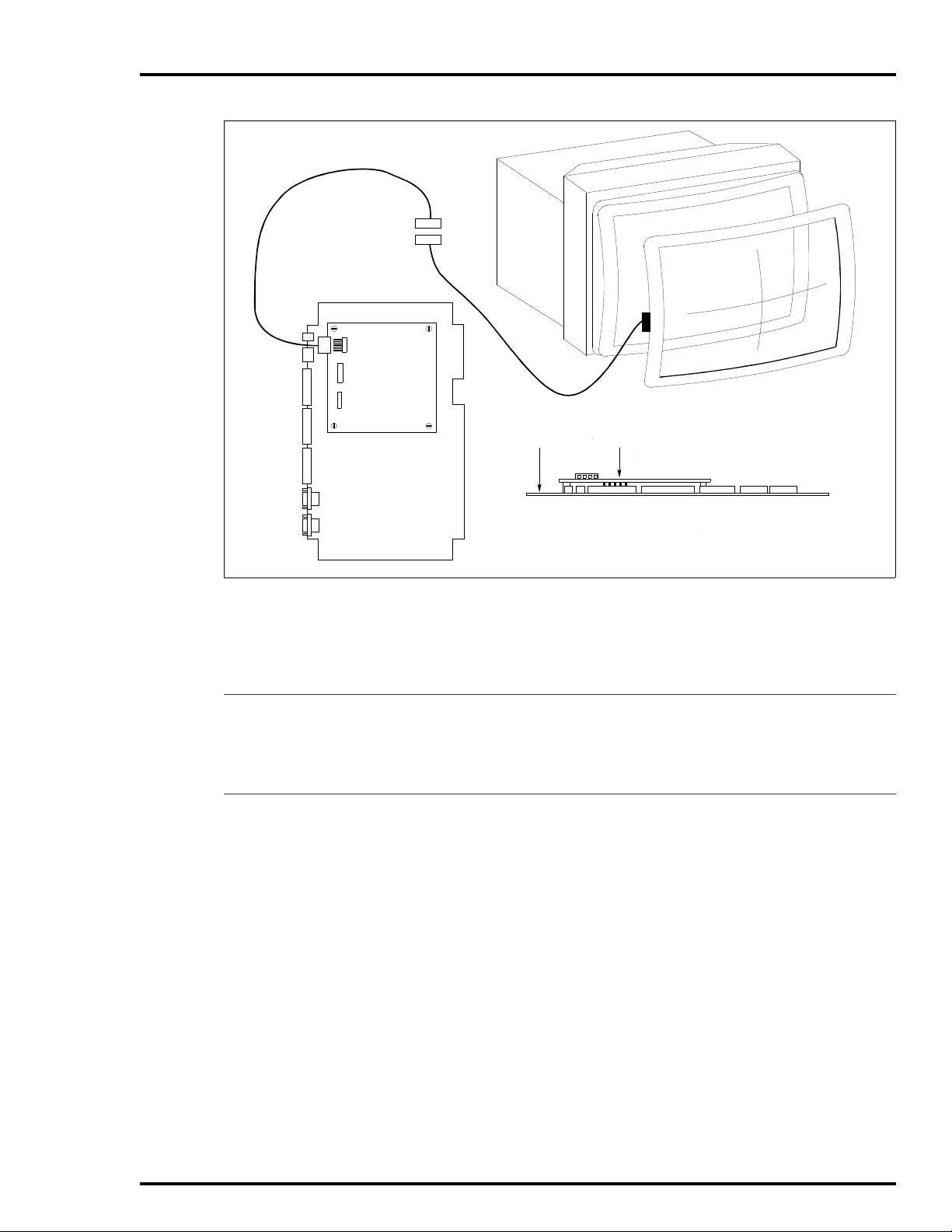
MKM BOARD
P15
P14
INSTALLATION
COMPONENT
SIDE
TOUCH SCREEN
CARD 1
TP80549 A .
Figure 3-22. Touch Screen Controller Card Connections
6. Attach the touch screen controller card to the MKM card
with the four nylon spacers and screws.
CALIBRATING THE TOUCH SCREEN
On-line calibration can be done from the console. For operating
information, refer to the operation and configuration instruction.
TOUCH SCREEN JUMPER AND SWITCH SETTINGS
Jumpers J6 and J8 on the IIMKM02A keyboard module control the touch screen option (Figure 3-23). Switch S1 and S2 on
the touch screen controller board must also be set.
1. Set jumpers J6 and J8 at 2 to 3 on the IIMKM02A board.
2. Jumpers J7 and J9 are for future use.
NOTE:
cable then connects the touch screen controller directly to the CPU
port 1. When not using the touch screen option, jumpers J6 and J8
can be in any position.
Setting jumpers at 2 to 3 disconnects the IIMKM02A lead. A
3. Set switches S1 and S2 on the touch screen controller
board. See Figure 3-23 for settings.
OPERATOR INTERFACE DEVICES
I-E96-192-5A 3 - 29
Page 53

INSTALLATION
®
TOUCH SCREEN
CABLE
NOT USED
CONNECTOR
PINS PLUG INTO
MKM BOARD
S2
4321
CLOSED - ON
S1
87654321
CLOSED - ON
1
5
P15
P14
J9
123 123
J8
123
P14
R3
S2
S1
W3
W4
J7
P17
J6
123
MOUNTING
HOLES (4)
FACTO RY
SET 2-3.
DO NOT
CHANGE.
IIMKM02A
J4
12 3
P3
P4
P5
P6
P7
J2
P8
J1
P9
P15
P18
FOR TOUCH
SCREEN
J3
123
J5
3
2
1
PERIPHERALS
P16
Figure 3-23. Touch Screen Switch and Jumper Settings
4. Jumpers W3 and W4 on the touch screen controller board
are factory set at pin 2 to 3 and should not be disturbed.
The peripheral devices in this instruction are limited to the
printers that can be used with the IIOIC42 operator interface
console. Either an Okidata or Genicom printer connects to
port 1 on the OIC CPU using cable part number 6642555A1.
Refer to the appropriate IIOIS41 or IIOIS42 instruction manual
for details on printer configuration, operation and cabling
requirements.
NOTE:
or a printer, not both.
Port 1 of th e CPU wi ll acce pt ei ther th e touc h scre en opti on
Refer to the manufacturer's documentation for more information on peripheral devices.
TP80550A .
PERIPHERALS
3 - 30 I-E96-192-5A
Page 54

SOFTWARE INSTALLATION AND START-UP
Once the auxiliary consoles are installed and wired and ready
for operation, refer to the appropriate OIS manual (listed in
REFERENCE DOCUMENTS in Section 1) for protocol, configu-
rations, software installation, start-up procedures and system
operation.
Make sure that all voltage labels and voltage switch settings on
the peripheral devices, power supply and power entry panel
show the correct operating voltage. Equipment damage may
result if the incorrect voltage is connected. Make sure the con-
CAUTION
ATTENTION
sole main power circuit breaker is off before changing operating voltage setting or equipment damage may result.
Remove power from all peripheral equipment and the console
before installing or removing peripheral equipment. Equipment
damage may result.
Assurez-vous que toutes les indications de tension et tous les
réglages de tension sur les périphériques, l e bloc d´alimentation et le panneau d´entrée des alimentations correspondent
bien à la tension de service. Une tension incorrecte risque
d´endommager l´equipment. Assures-vous que le disjoncteur
d´alimentation principal de la console est étient avant de modifier les réglages de tension de service afin d´éviter d´endommager l´équipment.
INSTALLATION
Coupez l´alimentation des périphériques et de la console avant
d´installer ou de retirer des périphériques, sinon l´équipment
risque de subir des dommages.
SOFTWARE INSTALLATION AND START-UP
I-E96-192-5A 3 - 31
Page 55
INTRODUCTION
TROUBLESHOOTING
SECTION 4 - TROUBLESHOOTING
This section explains how to troubleshoot the OIC operator
interface. It contains a troubleshooting table and techniques
for gathering information on software faults.
Replace components by following the procedures in Section 6.
Refer to information in Section 3 when replacing parts. Review
specific adjustments associated with replaceable parts before
returning the system to normal operation. Close and secure
cabinet doors on applicable models after troubleshooting or
replacing parts and before returning the system to normal
operation.
Be sure to follow all warnings, cautions and notes. Put circuit
boards containing MOS devices into antistatic bags when
stored or shipped back to the factory. Do not repair printed circuit boards in the field. All repairs and adjustments should be
performed by qualified personnel.
Symptom Possible Problem or Solution
No power indicator on
circuit
Breaker off but
indicator on
Improper/ incomplete
start-up
Start-up OK but no
keyboard response
Start-up OK but no CRT
picture
The OIC consoles are shipped ready for operation. After completing the instructions given in Section 3, prepare the unit for
service. The troubleshooting guide in Table 4-1 helps identify
problems and suggest solutions.
Table 4-1. Troubleshooting Guide
No AC power at console. Check AC wiring on input. Check AC on power
entry panel or keyboard interface ass em bly. Check breaker light on power
entry panel or keyboard interface.
Check breaker contacts. Check breaker wiring. Check AC input wiring.
Refer to the CPU customer hardware information
the console.
Check keyboard assignment. Check all cables. Check caps lock position.
Check IIMKM02A module seating and jumpers. Check main OIS configuration (keyboards/printers).
Check monitor AC po wer. Che ck RGB cabl es. C heck mon itor sw itch (s ync
on green). Check resistor switches for 75 ohm termination. Check brightness and cont rast controls.
instruction shipped with
INTRODUCTION
I-E96-192-5A 4 - 1
Page 56

TROUBLESHOOTING
DIAGNOSTIC POWER UP TESTS
If the troubleshooting guide fails to identify a problem in the
OIC console, follow the AC and DC power test procedures.
Check the AC voltages at the line input to the power entry
panel on all models except the tabletop. On the tabletop model,
the AC voltage is on the keyboard interface assembly.
AC Power Test
®
NOTE:
sole, switch the main breaker to the ON position. To turn off the
power, switch the main circuit breaker to the OFF position.
When the instructions state to apply power to the OIC con-
1. Turn off power to the console. Disconnect AC power to all
equipment inside the console by unplugging the line cords
from the back of the power entry panel (keyboard interface
assembly for the IIOIC421 tabletop).
2. Apply power to the console by switching on the line circuit
breaker.
3. Use a digital voltmeter to measure the AC power at each of
the outlets as follows:
IIOIC421 tabletop: keyboard interface assembly has one
outlet marked AC OUT.
IIOIC422 console: power entry panel has five outlets
marked UPPER CRT, LOWER CRT, POWER SUPPLY,
BLOWER AUX. The fifth outlet is on the front of the unit
and is marked PERIPHERAL POWER.
IIOIC423 environmental: power entry panel has four outlets marked CRT, TERMINAL, LIGHT, A/C.
IIOIC424 panel mount: power entry panel has one outlet
marked CPU POWER.
4. The line voltage should be 90 to 132 VAC RMS for a 120-VAC
input and 180 to 264 VAC for a 240-VAC input. Refer to the Site
Planning and Preparation instruction for specific AC voltages.
5. Use the digital voltmeter to check each outlet and insure
that neutral, live and ground are wired correctly, and there are
no ground faults. Refer to Section 3 and Section 6.
6. Turn off the power to the console. Verify that it removes
power from all outlets.
DIAGNOSTIC POWER UP TESTS
4 - 2 I-E96-192-5A
Page 57

DC Power Test
TROUBLESHOOTING
Follow these steps to test the DC power supply. The necessary
test equipment consists of a digital voltmeter. Figures 6-5, 6-6,
6-7 and 6-8 show the main power supply.
1. Turn off power to the console.
NOTE:
cage (IIOIC422 models).
Do not disconnect the power wiring from the multibus card
2. Unplug DC power distribution cables from all peripheral
devices (ADP panel and keyboard interface board, if present).
Disconnect the power cables at the distribution side of the
cables.
3. Make certain the power line cord for the power supply is
plugged into the power entry panel (keyboard interface assembly for the IIOIC421 tabletop).
4. Insure that all power supply wiring is correct. Refer to
Section 3 and Section 6.
5. Apply power to the console.
6. Measure the DC voltages at the multibus card module
backplane for the IIOCI422 models and at connector P16 of the
IIMKM02A module for all other OIC models.
7. Take the voltage measurements with the power supply
under load. Measure the +5.00 VDC; the voltage should be
+0.25 VDC and -0.0 VDC of the value. Measure the
+12.00 VDC and -12.00 VDC; the voltage should be +1.5 VDC
and -1.00 VDC of the value.
NOTE:
are not in tolerance.
Unstable operation may result if the power supply voltages
8. Turn off the power to the console.
9. Connect all DC power distribution cables removed in Step 2.
10. Apply power to the console and check the DC voltage levels
again. Adjust the power supply to obtain the voltage within a
tolerance of +0.05 V.
DIAGNOSTIC POWER UP TESTS
I-E96-192-5A 4 - 3
Page 58

INTRODUCTION
SECTION 5 - MAINTENANCE
This section contains a preventive maintenance schedule for
the OIC console. Be sure to follow all warnings, cautions and
notes. Put boards containing semiconductors into antistatic
bags when stored or shipped back to the factory. Do not repair
printed circuit boards in the field. All repairs and adjustments
should be performed by qualified personnel.
The reliability of any stand alone product or control system is
affected by the maintenance of the equipment. Elsag Bailey
recommends that all equipment users practice a preventive
maintenance program that will keep the equipment operating
at an optimum level.
This section presents procedures that the customer should be
able to perform on site. These preventive maintenance procedures should be used as a guideline to assist in establishing
good preventive maintenance practices. Select the minimum
steps required to meet the cleaning needs of your system.
Personnel performing preventive maintenance should meet the
following qualifications:
•
Maintenance personnel should be qualified electrical technicians or engineers that know the proper use of test equipment.
•
Maintenance personnel should be familiar with both the
OIC and the main OIS console, have experience working
with process control systems, and know what precautions
to take when working on live AC.
PREVENTIVE MAINTENANCE SCHEDULE
Table 5-1 is the preventive maintenance schedule and check
list for the OIC console. The table lists the preventive maintenance tasks in groups according to their specified maintenance
interval. Some tasks in Table 5-1 are self explanatory. Instruction for tasks that require further explanation are covered
under STANDARD PREVENTIVE MAINTENANCE PROCE-
DURES or in the manufacturer's documentation supplied with
the console.
INTRODUCTION
I-E96-192-5A 5 - 1
Page 59
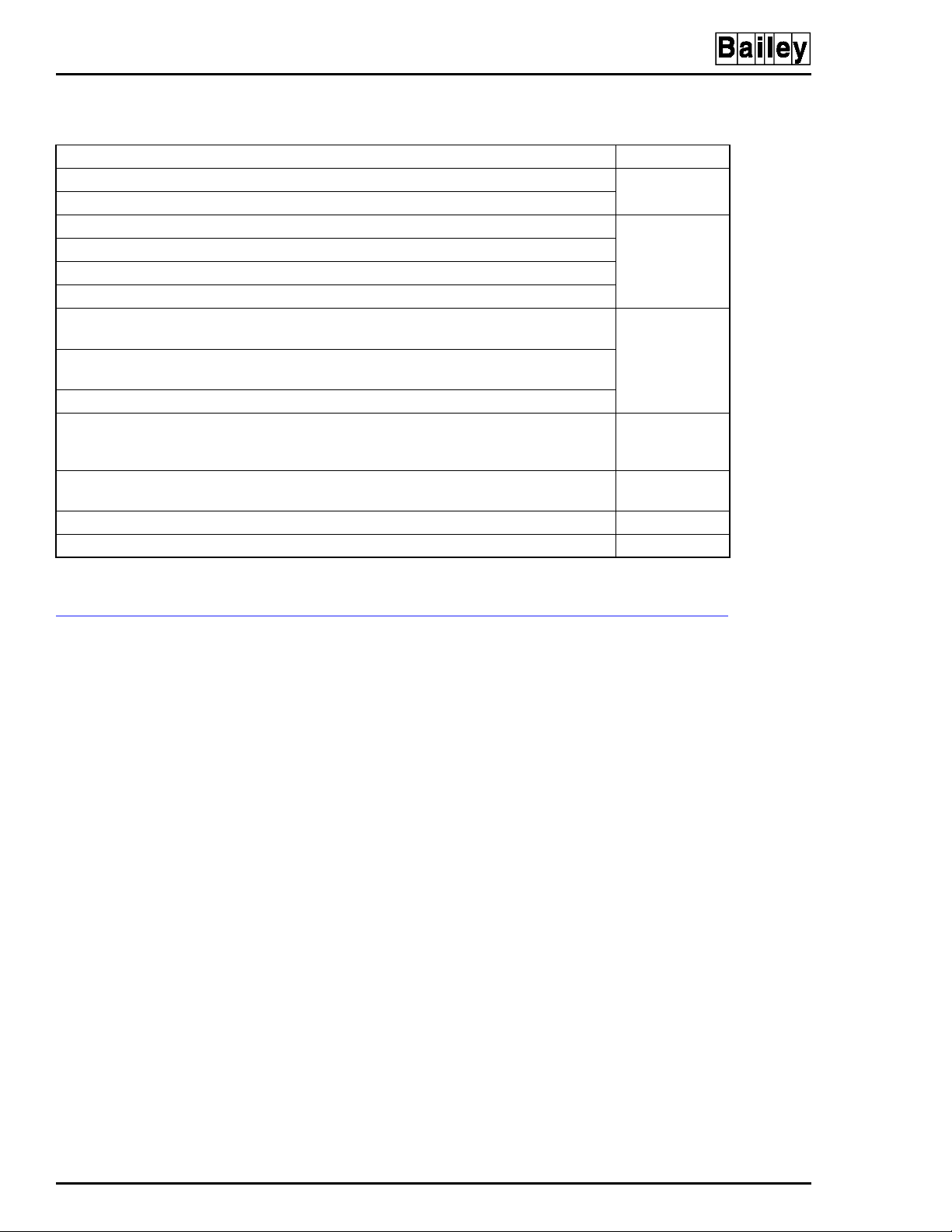
MAINTENANCE
Table 5-1. Preventive Maintenance Schedule and Check List
Task Frequency
Check printer, clean and lubricate.
Be sure fans are turning. With power off, wipe dust off all fan blades.
Check cabinet and module for dust. Clean as necessary using an antistatic vacuum. 3 months
Adjust printer per manufacturer's instructions.
Check power supply output . Adj ust powe r suppl y i f need ed (
Check alarm and display LEDs.
Check the cabin et air fil ters. Clean or replac e them as necess ary. Check th e air fil ter more
frequently in excessi ve ly dirty env iro nm ents .
Check all signal , power and gr ound c onnection s within th e cabinet and verify that they a re
secure. Refer to procedure.
Check power supply outputs. Refer to procedure.
Check the quality of the plant power and grounding system. Follow the power and
grounding system verification procedures in the INFI 90 OPEN site preparation and planning instruction.
Inspect and check the power entry panel. In high vibration environments testing may be
necessary at shorter intervals. Refer to procedure.
Replace power supply. Call Elsag Bailey sales and service for information. 5 years
Complete all appropriate tasks in this table. Shutdown
NOTE:
1. Adjust the printer using the procedures in the manufacturer's documentation.
1
in Section 5).
DC Power Test
1 month
6 months
12 months
2 years
®
EQUIPMENT AND TOOLS REQUIRED
Following are tools and equipment required for maintenance
procedures.
•
Antistatic vacuum.
•
Bladed torque screwdriver (0 to 2.7 Newton meters - 0 to
24 inch-pounds).
•
4-inch bladed screwdriver.
•
16-inch bladed screwdriver.
•
Isopropyl alcohol (99.5 percent electronic grade).
•
Foam tipped swabs.
•
Eberhard Faber (400A) pink pearl eraser or equivalent.
•
Fiberglass burnishing brush.
•
Distilled water.
•
Lint free cloth.
•
Mild, all purpose commercial spray cleaner.
EQUIPMENT AND TOOLS REQUIRED
5 - 2 I-E96-192-5A
Page 60

STANDARD PREVENTIVE MAINTENANCE PROCEDURES
These preventive maintenance procedures cover standard procedures for the console preventive maintenance requirements.
Read through them before beginning the procedure.
Never clean electrical parts or components with the power on.
Doing so exposes you to a fatal electrical shock hazard.
MAINTENANCE
WARNING
AVERTISSEMENT
Checking Connections
Wear eye protection wheneve r wor king with cleani ng solve nts.
When removing solvents from printed circuit boards using
compressed air, injury to the eyes could result from splashing
solvent as it is blown off the printed circuit board.
Il ne faut jamais nettoyer des piècesou des composants électriques lorsqu'ils sont sous tension. Ceci présente un risque
d'électrocution fatale.
Portez toujours des lunettes de protection lorsque vous utilisez des solvants de nettoyage. L'aircomprimé servant à
enlever le solvant des cartes de circuits imprimés provoque
des éclaboussures qui risquent d'atteindre les yeux.
Check all signal wiring, power and ground connections within
the cabinet to verify their integrity. When checking connections, always turn a screw, nut or other fastening device in the
direction to tighten only. If the connection is loose, it will be
tightened. If the connection is tight, the tightening action will
verify that it is secure. There must not be any motion to loosen
the connection.
NOTE:
ventive maintenance task.
Power to the cabinet must be off while performing this pre-
1. Check and verify that all phase, neutral and grounding
conductor connections on the power entry panel are secure.
2. Check and verify that all other power connections within
the cabinet, including connections to the power supplies are
secure.
3. Check and verify that all field wiring connections to the
communication modules are secure.
Cleaning the Monitor
To clean the monitor window, remove dirt, finger prints or
grease with a commercial glass cleaner and a soft lint-free
cloth.
STANDARD PREVENTIVE MAINTENANCE PROCEDURES
I-E96-192-5A 5 - 3
Page 61

MAINTENANCE
Cleaning the Operator Keyboard
To clean the operator keyboard:
1. Wipe away dust with a soft lint free cloth.
2. Clean dirt and film from the keyboard using a mild all purpose commercial spray cleaner and lint-free cloth.
Cleaning the Engineering Keyboard
To clean the engineering keyboard:
1. Use a static safe vacuum cleaner to remove dust from the
keyboard.
2. Clean the key caps and keyboard enclosure with an all
purpose commercial spray cleaner and lint free cloth. Do not
spray into the keyboard. Apply cleaner to the cloth only.
®
Cleaning the Printed Circuit Boards
There are several circuit board cleaning procedures in this section. These procedures cover circuit board cleaning and cleaning edge connectors. Use the procedures that meet the needs
of each circuit board. Remove all dust, dirt, oil, corrosion or
any other contaminant from the circuit board.
Do all cleaning and handling of the printed circuit boards at
static safe work stations. Always observe the proper electrostatic sensitive device handling precautions when handling
printed circuit boards.
GENERAL CLEANING AND WASHING
If the printed circuit board needs minor cleaning:
Remove dust and residue from the printed circuit board surface using clean, dry, filtered compressed air or an antistatic
field service vacuum cleaner.
Another method of washing the printed circuit board is:
1. Clean the printed circuit board by spraying or wiping the
board with isopropyl alcohol (99.5% electronic grade). Use a
foam tipped swab to wipe the circuit board.
2. When the circuit board is clean, remove excess solvent by
using compressed air to blow it free of the circuit board.
STANDARD PREVENTIVE MAINTENANCE PROCEDURES
5 - 4 I-E96-192-5A
Page 62

MAINTENANCE
CLEANING EDGE CONNECTOR
To clean edge connector contacts:
1. Use a solvent mixture of 80% isopropyl alcohol (99.5%
electronic grade) and 20% percent distilled water.
2. Soak a lint-free cloth with the solvent mixture.
3. Work the cloth back and forth parallel to the edge connector contacts.
4. Repeat with a clean cloth that is soaked with the solvent
mixture.
5. Dry the edge connector contact area by wiping with a clean
lint-free cloth.
To clean tarnished or deeply stained edge connector contacts:
1. Use an Eberhard Faber (400A) pink pearl eraser, or equivalent to remove tarnish or stains. Fiberglass or nylon burnishing brushes may be used also.
2. Minimize electrostatic discharge by using the 80% to 20%
isopropyl alcohol to water solution during burnishing.
3. Do not use excessive force while burnishing. Use only
enough force to shine the contact surface. Inspect the edge
connector after cleaning to assure no loss of contact surface.
CLEANING FEMALE EDGE CONNECTORS
To clean the contacts on a female edge connector:
1. Use a foam tipped swab or a lint-free cloth wrapped over a
piece of scrap circuit board. Soak the swab or cloth in electronic grade isopropyl alcohol.
2. Insert the swab of cloth covered circuit board into edge
connector and work it back and forth to clean the contacts.
3. Rinse the edge connector contacts by spraying with isopropyl alcohol.
4. Remove excess alcohol and dry using compressed air.
Checking Power Supply Outputs
To check modular power supply outputs on the power entry
panel, refer to the AC and DC power tests in Section 4.
STANDARD PREVENTIVE MAINTENANCE PROCEDURES
I-E96-192-5A 5 - 5
Page 63

MAINTENANCE
Checking and Inspecting Power Entry Panel
The system must be shut down to perform this maintenance
task.
1. Check the tightness of all power wiring screws within the
console. Torque all screws connected to AC power to 1.58 Newton meters (14 in-lbs).
2. Inspect and clean the power entry panel and DC distribution board connections.
®
STANDARD PREVENTIVE MAINTENANCE PROCEDURES
5 - 6 I-E96-192-5A
Page 64

SECTION 6 - COMPONENT DESCRIPTION AND REPLACEMENT
INTRODUCTION
This section provides a description of components and
explains how to replace the components in the OIC console. It
contains jumper and dipswitch settings and also component
locations and settings. There are no special tools required.
Components in the OIC consoles are configured at the factory.
This information is given in case settings are changed or hardware needs to be replaced.
Table 6-1 lists the hardware used in the OIC operator interfaces that are covered in this section.
IIMKM02A MULTIBUS KEYBOARD MODULE
The multibus keyboard module interfaces the keyboard and
other operator input devices to the OIC console. The location of
the module varies depending on which type of OIC is being
used. There are six jumpers on the MKM board to set for
proper operation (Figure 6-1).
Table 6-1. Hardware
Nomenclature
or Part Number
1948623A9 x x x x 19-inch color monitor
6638353A7 x Power entry panel
6638514A1 x x x x Keyboard assembly
6638553A5 x Power supply assembly
6638554A2 x x x keyboard interface assembly
6639030A5 x keyboard interface assembly
6639503A5 x
6640038A1 x x x Power supply
6640300A1 x Four slot multibus card cage
6640851A2 x
IIADP01 x x x Annunciator/display panel (tabletop - optional)
IIADP02 x x Annunciator/display panel
IIAKB04 x x x
IIAMS04 x x x Mouse
IIATB05 x x x Trackball
IIMKM02A x x x x Multibus keyboard module
NADS03 x Annunciator display panel
NOTES:
1. Includes keyboard interface assembly.
2. IIOIC423 requires an IIAKB04 without the adapter.
OIC Model Description
421 422 423 424
1
2
x QWERTY engineering keyboard
Power entry panel
1
Power entry panel
Hardware Description
mylar
(
)
INTRODUCTION
I-E96-192-5A 6 - 1
Page 65

COMPONENT DESCRIPTION AND REPLACEMENT
TO PFI ON
POWER SUPPLY
TO RE S ET SWITCH ON
POWER E NTRY PANEL
P3
P4
P15
J4
123
J5
®
3
2
1
TO KE YB OA R D
INTERFACE BOARD
TO TE R MIN A L
BLOCK ON POW ER
ENTRYPANEL
TO ADP AND KEYBOARD
INTERFACE BOARD
TO KE YB OA R D
PORT ON CPU
TO PORT 0
ON CPU
P5
P6
P7
P8
P9
J9 J7
123
J8
123
P14
J2
J1
123
P17
J6
123
P18
P16
POWER CONNECTOR FOR
IIMKM02A WHEN USED ON THE
IIOIC421, IIOIC423 AND IIOIC424.
NOTUSEDINIIOIC422.
Figure 6-1. IIMKM02A Multibus Keyboard Module
J3
123
TP80551A
Jumpers J1 and J2 control serial ports one (P8) and two (P9).
Connecting the eight pins horizontally configures the serial
port for data to be transmitted from the MKM module on pin
three of the connector and received from the connected device
on pin two of the connector. Connecting the eight pins vertically as shown for P9 in Figure 6-1 configures the serial port
for data to be transmitted from the MKM module on pin two of
the connector and received from the connected device on pin
three of the connector.
Jumper J3 resets the OIC multibus card cage when the MKM
watchdog timer circuit times out. Set the jumper to J3 pins
one and two for OIC reset on time-out. Set the jumper to J3
pins two and three for no OIC reset on time-out. Factory
default is no reset on time-out.
Jumper J4 allows the option of disabling the power supply
out-of-tolerance (OOT) signal to reset the MKM module. Set the
IIMKM02A MULTIBUS KEYBOARD MODULE
6 - 2 I-E96-192-5A
Page 66

COMPONENT DESCRIPTION AND REPLACEMENT
jumper to J4 pins one and two to disable the OOT signal. Set
the jumper to J4 pins two and three to enable the OOT signal.
Factory default is to disable OOT on all OIC consoles
NOTE:
to 250 milliamps. The two digital inputs are rated at up to 250 milliamps (futu re).
The two digital outputs are open collector type which sink up
Jumper J5 must be set to pins two and three.
Jumpers J6 and J8 are for consoles with the touch screen
option. Setting the jumpers to J6 and J8 pins two and three
disconnects the MKM lead. A cable then connects the touch
screen controller board directly to the CPU port 1.
Jumpers J7 and J9 are reserved for future use and are not
used on the IIOIC42 console.
IIMKM02A MULTIBUS KEYBOARD MODULE REPLACEMENT
Failure to turn off the main power circuit breaker before remov-
CAUTION
ing or inserting modules into the card cage may result in
equipment failure.
Si l'on omet d'eteindre l'interrupteur du circuit d'alimentation
ATTENTION
principal avant de retirer les cartes ou de les inserer dans le
porte-cartes, l'equipment pourrait faire default.
IIOIC422 Console
The IIMKM02A multibus keyboard module is the only module
used in the IIOIC42 console. The multibus keyboard module
connects the keyboard interface assembly to the CPU.
In the IIOIC422 model, the MKM board is located in the multibus card cage. Remove the module from the multibus card
cage by following these steps:
1. Open the door on the front of the cabinet and turn off the
main power circuit breaker.
2. Remove the required cables.
3. Loosen (do not remove) the two screws in the left and right
card retaining brackets.
4. Slide the left and right card retaining brackets out of the
way to permit the module removal tabs on the card to pass.
5. To unseat a module, lift the module removal tabs.
6. Carefully slide the module out of the multibus card cage.
7. Check the jumper settings on the new module before
assembling into the card cage.
IIMKM02A MULTIBUS KEYBOARD MODULE REPLACE ME NT
I-E96-192-5A 6 - 3
Page 67

COMPONENT DESCRIPTION AND REPLACEMENT
®
All other models
MULTIBUS CARD CAGE
For the tabletop, environmental and panel mounted consoles,
the location of the MKM board varies.
1. Remove power to the console.
2. The MKM module has four retaining screws. Remove the
attaching hardware and disconnect any cables.
3. Check the jumper settings on the new module before
assembling.
The multibus card cage provides power and mounting for the
IIOIC422 console multibus keyboard module. Figure 1-2
shows the component locations for the IIOIC4221 (lower monitor) consoles.
Figure 6-2 shows the front view of the card cage. Figure 6-3
shows the rear view of the multibus card cage.
To remove a multibus card cage:
1. Turn off the main circuit breaker on the power entry panel.
Check the power indicator to see if power is removed.
2. Follow the procedure in this section to remove the MKM
multibus keyboard module to a static safe location.
3. Disconnect and label all cables from the card cage.
4. Support the back and front of the card cage and remove
the four screws at the front of the card cage (two on each side).
5. Carefully slide the cage out the front of the cabinet.
TO P ORT 0
ON CPU
TO KEYBOARD
PORT ON CPU
MKM
P9P8
TP80552A
Figure 6-2. IIOIC422 Multibus Card Cage (Front View)
MULTIBUS CARD CAGE
6 - 4 I-E96-192-5A
Page 68

FAN
COMPONENT DESCRIPTION AND REPLACEMENT
-12
+12
+5
COM
P5
Figure 6-3. IIOIC422 Multibus Card Cage (Rear View)
FAN ASSEMBLY FOR THE CARD CAGE
Figure 6-3 shows the fan in a console card cage. Refer to Table
7-1 for the part number for the 11.43 cm (4-1/2 in) fan. Use
this procedure to remove the fan from a console.
1. Turn off the main circuit breaker on the power entry panel.
Check the power indicator to see if power is removed. Cut and
remove cable ties securing the fan assembly power cord.
2. Remove the two long screws on either side of the fan
assembly and slide the fan assembly out around the multibus
card cage.
NOTES:
1. Be sure the arrow on the fan being installed points in the direction of the air flow.
P6
-12
+12
+5
COM
TP36141B
2. Be sure the red striped conductor of the power cord is connected to the + (positive) terminal of the fan.
POWER SUPPLY REMOVAL
The 130-watt power supply provides power to the OIC console.
The power supply location and part number varies according
to the model of OIC. Refer to Table 6-1 for the power supply
part numbers. Figures 1-1 through 1-4 in Section 1, show the
location of the power supply for the various models.
IIOIC422 and IIOIC423 models have a DC distribution board
attached to the power supply. Table 6-2 lists the DC distribution socket connections. Table 6-3 lists the pin outs to the DC
distribution board sockets. Each socket on the DC distribution
board is wired identically.
FAN ASSEMBLY FOR THE CARD CAGE
I-E96-192-5A 6 - 5
Page 69

COMPONENT DESCRIPTION AND REPLACEMENT
Table 6-2. DC Distribution Board Socket Connections
Socket Console Connection
P1 IIMKM02A (IIOIC423 only)
P2 —
P3 Keyboard interface board
P4 IIADP02
P5 Backplane (IIOIC422 only)
P6 Backplane (IIOIC422 only)
P7 Fans (card cage and door) (IIOIC422 only)
P8 Fan (monitor)
Table 6-3. DC Distribution Board Pin Outs
Terminal Socket Description
1 1 +12V
22Common
3 3 -12V
4 4 No connection
5-6 5 +5V
7-8 6 Common
®
Refer to Section 3 for cable part numbers and connection
information. Figure 6-4 shows the connections from the power
supply to the DC distribution board.
NOTE:
and 240 volts. The power supply is voltage autosensing and has no
voltage select jumpers.
The power supply in the cons oles op erates on both 1 20 volt s
DC DISTRIBUTION BOARD 6638235A1
TO P2 ON
POWER SUPPLY
P2
4
5
6
P1
4
5
6
12 876543
P4
4
1
2
5
6
3
P3
4
1
2
5
6
3
1
2
3
1
2
3
6638710A9
P6
4
5
6
P5
4
5
6
1
2
3
1
2
3
P8
4
1
2
5
6
3
P7
4
1
2
5
6
3
TO E1 CH ASSIS
GROUND ON PEP
TP80553A
Figure 6-4. Connections to DC
Distribution Board
POWER SUPPLY REMOVAL
6 - 6 I-E96-192-5A
Page 70

IIOIC421 Tabletop
COMPONENT DESCRIPTION AND REPLACEMENT
To remove the power supply from an IIOIC421 tabletop model,
see Figure 6-5 and follow these steps:
1. Remove power.
2. To remove the cover from the top of the monitor, remove
the eight screws and remove the split cover. Do not remove the
monitor.
3. Mark and disconnect the wires on the power supply.
4. Carefully tip the monitor and chassis on one side or tip it
to the left and support it.
5. Remove the four screws from the outside bottom of the
chassis fastening the power supply to the chassis.
6. Set the monitor and chassis back upright and replace the
cover.
COVER MOUNTING
SCREWS (8)
POWER SUPPLY
MOUNTING SCREWS
ON BOTTOM O F
CHASSIS
TP35533B
Figure 6-5. Power Supply Removal for
IIOIC421 Tabletop Console
POWER SUPPLY REMOVAL
I-E96-192-5A 6 - 7
Page 71

COMPONENT DESCRIPTION AND REPLACEMENT
IIOIC422 Console
To remove the power supply from an IIOIC422 console see Figure 6-6 and follow these steps:
1. Turn off the main circuit breaker on the power entry panel.
Check the power indicator to see if power is removed.
2. Remove the power supply plug from the socket on the
power entry panel.
3. Mark and disconnect the wires between the power supply,
DC distribution board and multibus card cage backplane.
4. Remove the two nuts holding the power supply bracket to
the monitor mounting platform and slide the unit out the rear
of the cabinet.
®
REAR VIEW
MONITOR
POWER SUPPLY
MOUNTING SCREW S
AND NUTS (2)
TP36165C
Figure 6-6. Power Supply Removal for IIOIC422 Consoles
POWER SUPPLY REMOVAL
6 - 8 I-E96-192-5A
Page 72

IIOIC423 Environmental Cabinet
TP35370
B
3SCREWS
DCDISTRIBUTIO
N
To remove the power supply from an IIOIC423 environmental
cabinet see Figure 6-7 and follow these steps:
1. Follow the procedure for removing the IIOIC423 power
entry panel in this section.
2. Remove the IIMKM02A circuit board. Do not lose the two
nonconductive washers for each standoff.
3. To remove the cover from the top of the power entry panel,
remove the nine screws shown in the figure and disconnect the
DC distribution board connector.
4. Mark and disconnect the wires between the power supply
and incoming AC.
5. Remove the four screws holding the power supply to the
center support wall of the power entry panel.
COMPONENT DESCRIPTION AND REPLACEMENT
NOTE:
Check that the DC distribution board connector to the power
supply is aligned correctly when replacing the cover.
4 SCREW S
NOTE: DO NOT LOSE NON-CONDUCTIVE
WASHERS ON MKM BOARD STANDOFFS
3SCREWS
ON COVER
4 SCREW S ON CENTER
SUPPORT WALL
POWER SUPPLY
ON COVERMKM BOARD
DC DISTRIBUTION
BOARD CONNECTOR
FRONT VIEW
BOARD
3 SCREW S
ON COVER
Figure 6-7. Power Supply Removal for IIOIC423 Environmental Console
POWER SUPPLY REMOVAL
I-E96-192-5A 6 - 9
Page 73

COMPONENT DESCRIPTION AND REPLACEMENT
IIOIC424 Panel Mount
To remove the power supply from an IIOIC424 panel mounted
model see Figure 6-8 and follow these steps:
1. Remove power.
2. To remove the power entry panel, remove the two chassis
screws on the upper edge of the back panel and carefully slide
the unit out far enough to access the power supply mounting
screws. It is not necessary to remove the monitor.
3. Mark and disconnect the wires on the power supply.
4. Remove the four screws from the outside bottom of the
chassis fastening the power supply to the chassis.
®
POWER ENTRY PANEL
POWER SUPPLY
MOUNTING SCREWS
ON BOTTOM OF
CHASSIS
CHASSIS
SCREWS (2)
TP35534A
Figure 6-8. Power Supply Removal for IIOIC424
Panel Mount Console
The power entry panel is used on all OIC models except the
IIOIC421 tabletop. Location and part numbers of the power
entry panels used on the OIC consoles vary depending on the
model. The power entry panel contains the incoming AC power
terminals and system circuit breakers along with ports for
connecting peripheral devices and terminals for alarm contact
outputs. The power entry panel also contains the system reset
switch and the degaussing switches for the monitors. Refer to
Table 6-1 for the power entry panel part numbers.
On the IIOIC422 console model, use the upper degauss switch
to correct picture distortion due to magnetic fields on the
screen of the upper (swivel mounted) monitor. Use the lower
POWER ENTRY PANEL
6 - 10 I-E96-192-5A
Page 74

COMPONENT DESCRIPTION AND REPLACEMENT
degauss switch to correct picture distortion due to magnetic
fields on the screen of the lower monitor.
The system reset pushbutton resets the OIC multibus keyboard module (IIMKM02A) to an initial power up condition
when pressed.
A terminal block connects annunciators to user-defined
alarms. The terminal designation is printed on the panel
beside the terminal. The digital in (DI) and digital out (DO) terminals are not used.
The power indicator is lit when the AC power is connected to
the power entry panel and the main power circuit breaker is
on.
Either 120 or 240-VAC power is used to supply power to the
IIOIC42 operator interface console. The AC in is either hard
wired (IIOIC422 model) or uses a 3-prong plug connector on
the power entry panel.
IIOIC422 Console
NOTES:
1. Use the AC outlet for the intended purpose only.
2. Refer to Section 3 for wiring and cable connections. Some of
the connections are on the back of the power entry panel and are
accessed through the door on the back of the OIC console.
To remove the power entry panel from an IIOIC422 console,
see Figure 6-9 and follow these steps:
1. Turn off the main circuit breaker on the power entry panel.
Check the power indicator to see if power is removed.
2. Shut down AC line power to cabinet (plant breaker) so that
the AC line may be disconnected safely.
3. Remove all cables from the front of the power entry panel.
4. Remove AC cables from the outlets on the power entry
panel.
5. Remove the signal cable from the multibus keyboard module that goes to the rear of the power entry panel. Leave the
cables on the power entry panel. The new power entry panel
comes with cables.
6. Remove the five screws from around the front of the power
entry panel. Slide the power entry panel out the front of the
cabinet.
POWER ENTRY PANEL
I-E96-192-5A 6 - 11
Page 75

COMPONENT DESCRIPTION AND REPLACEMENT
FRONT VIEW
POWER ENTRY
PANELMOUNTING
SCREWS (5)
®
IIOIC423 Environmental Cabinet
To remove the power entry panel from an IIOIC423 environmental cabinet see Figure 6-10 and follow these steps:
1. Turn off the main circuit breaker on the power entry panel.
Check the power indicator to see if power is removed.
2. Shut down AC line power (plant breaker) so that the AC
line may be disconnected safely.
3. Remove all cables from the front and top of the power entry
panel and IIMKM02A cable. Refer to Section 3 for IIOIC423
cable connections..
CPU
TP80578A
Figure 6-9. Power Entry Panel (PEP) Removal
for IIOIC422 Consoles
4. Remove AC cables from the outlets on the power entry
panel.
5. Remove the two screws from the power entry panel end of
the bracket supporting the front of the power entry panel. If
the cabinet end of the bracket is removed, seal the mounting
POWER ENTRY PANEL
6 - 12 I-E96-192-5A
Page 76

COMPONENT DESCRIPTION AND REPLACEMENT
POWER ENTRY
PANEL CABINET
MOUNTING
SCREWS (4)
POWER ENTRY
PANEL SUPPORT
MOUNTING
SCREWS (2)
POWER ENTRY
PANEL
Figure 6-10. Power Entry Panel (PEP) Removal for IIOIC423 Environmental Cabinet
®
screws with Dow Corning 732
RTV clear sealant or equivalent
when reassembling.
6. Remove the four screws from around the power entry
panel.
7. Slide the power entry panel out the front of the cabinet.
Use caution as the power entry panel weighs approximately
23 kg (50 lbs).
IIOIC424 Panel Mount
To remove the power entry panel from an IIOIC424 panel
mount model see Figure 6-11 and follow these steps:
TP35537B .
1. Turn off the main circuit breaker on the power entry panel.
Check the power indicator to see if power is removed.
® Registered trademark of Dow Corning Company.
™ Trademark of Dow Corning Company
POWER ENTRY PANEL
I-E96-192-5A 6 - 13
Page 77

COMPONENT DESCRIPTION AND REPLACEMENT
POWER ENTRY PANEL
CPU
Figure 6-11. Power Entry Panel Removal
for IIOIC424 Panel Mount
REMOVE
2 SCREW S
FROM REAR
OF PANEL
TP80564A
®
2. Shut down AC line power to the panel (plant breaker) so
that the AC line may be disconnected safely.
3. Label and disconnect all cables to the power entry panel.
4. From the back of the panel, there are two screws securing
the power entry panel with its mounting tray. Remove the two
screws and slide the power entry panel/mounting tray out the
rear of the panel.
OPERATOR INTERFACE DEVICES
This section contains information and the removal instructions for the operator and engineering keyboards, mouse/
trackball, the annunciator display panel, keyboard interface
assembly and the color monitor. Follow all warnings and cautions.
Operator and Engineering Keyboards, Mouse, Trackball
The mylar operator keyboard plugs into the KEYBOARD port
on the keyboard interface assembly. The engineering keyboard
plugs into the AUX KBD port on the keyboard interface assembly. The IIAMS04 mouse or IIATB05 trackball plugs into the
keyboard interface assembly at the MOUSE/TRACKBALL port.
Unplug these devices to remove them.
NOTE:
or trackball.
The IIOIC423 environmental model does not use the mouse
OPERATOR INT ERFACE DEVICES
6 - 14 I-E96-192-5A
Page 78

Annunciator Display Panel
COMPONENT DESCRIPTION AND REPLACEMENT
There are three types of annunciator display panels available
for the OIC consoles. They are the IIADP01, IIADP02 and
NADS03. Ribbon cable maximum length is 4.5 meters
(15 feet). Refer to OPERATOR INTERFACE DEVICES in
Section 3 for installation information.
IIOIC421 TABLETOP MODEL
The tabletop model does not come with an ADP panel, but the
IIADP01 tabletop assembly can be added to it. This 32-LED
and pushbutton assembly is driven off the keyboard/interface
board and the cable is connected to the AUX PORT. Unplug
the cable to remove.
Refer to Section 3 for address switch settings.
IIOIC422 CONSOLE MODEL
MOUNTING
SCREWS
FOR ADP (4)
KEYBOARD
INTERFACE
ASSEMBLY
POWER SUPPLY
DC DISTRIBUTION
BOARD
The console model comes with the IIADP02 assembly mounted
in the console (Figure 6-12). To remove the ADP:
1. Turn off the main circuit breaker on the power entry panel.
Check the power indicator to see if power is removed.
2. Disconnect all the cables.
REAR VIEW FRONT VIEW
ANNUNCIATOR
DISPLAY
PANEL (ADP)
KEYBOARD
INTERFACE
ASSEMBLY
POWER E NTRY
PANEL
MULTIBUS
POWER ENTRY
PANEL
CARD CAGE
CPU
TP80563A
Figure 6-12. ADP02 Removal from IIOIC422 Console
OPERATOR INTERFACE DEVICES
I-E96-192-5A 6 - 15
Page 79

COMPONENT DESCRIPTION AND REPLACEMENT
3. Remove the four screws securing the ADP panel to the console. Remove the ADP panel.
4. Refer to Section 3 for address switch settings for new ADP
panel.
®
NOTE:
console in addition to the IIADP02.
The IIADP01 tabletop panel can be added to an IIOIC422
IIOIC423 ENVIRONMENTAL MODEL
The environmental model comes with the NADS03 assembly
mounted in the cabinet (Figure 6-13). To remove the NADS03
assembly:
1. Turn off the main circuit breaker on the power entry panel.
Check the power indicator to see if power is removed.
Open the
rear doors and disconnect all the cables.
2. Remove the screws securing the sealing ring to the cabinet.
3. Once the sealing ring is removed, remove the four screws
securing the NADS03 to the cabinet.
4. Remove the NADS03 panel.
5. Refer to Section 3 for address switch settings for new
NADS03 panel.
6. Install the new NADS03 panel into the cabinet.
7. Install the sealing ring and ten screws to secure the ring to
the cabinet. Tighten the screws.
IIOIC424 PANEL MOUNTED MODEL
The panel mounted model does not come with an ADP panel,
but the IIADP01 tabletop display or the IIADP02 display can be
added to the assembly as an option. Refer to Section 3 for
installation information and cabling/connection information.
1. Turn off the main circuit breaker on the power entry panel.
Check the power indicator to see if power is removed.
2. If the optional IIADP01 tabletop unit is added, the cable
connects to AUX PORT of the keyboard interface board. To
remove, unplug the cable.
3. If the optional IIADP02 is added to the assembly and
mounted in a panel, remove any hardware that was required to
mount the ADP in the panel.
4. Refer to Section 3 for switch settings for ADP panel.
OPERATOR INT ERFACE DEVICES
6 - 16 I-E96-192-5A
Page 80

COMPONENT DESCRIPTION AND REPLACEMENT
NADS03
SEALING RING
RETAINING
SCREWS
Keyboard Interface Assembly
On the keyboard interface connector board, set positions 5, 6
CAUTION
and 7 of dipswitch SW1 to closed (on). Set positions 1 through
4 and 8 of dipswitch SW1 to open (off). Failure to configure
dipswitch SW1 properly will damage the CPU in the console.
Sur le circuit de raccor dement de l'interface du clavier , règler
les interrupteurs 5, 6 et 7 de SW1 à la position fermèe (ON).
ATTENTION
Règler les interrupteurs 1 à 4 et 8 de SW1 à la position ouverte
(OFF). Si les interrupteurs de SW1 ne sont pas configurés
adéquatement, le CPU de la console sera endommagé.
The keyboard interface assembly part number and location
varies according to OIC model. On the IIOIC421 tabletop console, the keyboard interface assembly is on the front of the
case below the monitor. The keyboard interface assembly is
located on the IIOIC422 console front panel next to the monitor behind a polycarbonate door. On the IIOIC423 environmental console, the keyboard interface assembly is on the
front of the power entry panel behind the front door. On the
TP80558A
Figure 6-13. NADS03 Removal from
IIOIC423 Environmental Cabinet
OPERATOR INTERFACE DEVICES
I-E96-192-5A 6 - 17
Page 81

COMPONENT DESCRIPTION AND REPLACEMENT
IIOIC424 panel mount consoles, the keyboard interface assembly is below the monitor and above the CPU. Refer to Table 6-1
for part numbers. Refer to Section 7 when replacing fuses for
fuse part numbers.
The keyboard socket is for the operator keyboard supplied with
the OIC consoles (Figure 6-14). The AUX 1 port is for a tabletop annunciator display panel. The auxiliary keyboard connector is for an engineering keyboard. Connector P9 is not used.
OFF
TUNE CONFIG
®
TO P7 ON
MKM BOARD
AND TO P2 ON
ADP BOARD
KEYBOARD
AUX 1
PORT
KEYBOARD INTERFACE ASSEMBLY FRONT VIEW
TO P5 ON
MKM BOARD
P1
P8
ASSY 6638238-1
P3
KEYBOARD
J2
2
1
BLU
RED
VIO
BRN
YEL
BLK
J1
F1 F3
AUX 1 PORT
SW1
F2
P4
MOUSE/
TRACKBALL
TO MOUSE
PORT ON CPU
SW1 SW ITCHES
5,6AND7ARE
CLOSED (ON)
MOUSE/TRACKBALL
P10
P5
AUX
KBD
GND
+12V
-12V
5V
NOT USED
P9
P2
TP P3 ON DC
DISTRIBUTION
BOARD. NOT USED ON
IIOIC421 O R IIO IC424.
F1, F2 AND F3
ARE 2-A, 250-V
P6
AUX KBD
FAST BLOW
CAUTION: SWITCHES 5, 6
AND 7 ARE CLOSED (ON).
SWITCHES 1 THROUGH 4
AND 8 ARE OPEN (OFF). IF
THEY ARE NOT SET
CORRECTLY, DAMAGE TO
THECPUMAYRESULT.
KEYBOARD INTERFACE ASSEMBLY CONNECTOR BOARD
TP80554A
Figure 6-14. Keyboard Interface Assembly (IIOIC422 Model)
OPERATOR INT ERFACE DEVICES
6 - 18 I-E96-192-5A
Page 82

COMPONENT DESCRIPTION AND REPLACEMENT
IIOIC421 TABLETOP MODEL
To remove the keyboard interface assembly from the tabletop
model:
1. Turn off the power to the tabletop model. Verify power is
removed.
2. Label and disconnect cables from the back of the monitor.
3. There is a slotted hole on the side of the monitor support
tube. Remove the screw in the slotted hole.
4. Carefully lift off the monitor to gain access to the keyboard
interface assembly. The monitor weighs about 27 kg (60 lbs).
Be sure it is well supported.
5. Label and disconnect the cables going to the keyboard
interface assembly.
6. The keyboard interface assembly is not attached to the table.
7. See Figure 6-14 for SW1 settings on new keyboard interface assembly.
IIOIC422 CONSOLE MODEL
To remove the keyboard interface assembly from an IIOIC422
console, see Figure 6-15 and follow these steps:
1. Turn off the main circuit breaker on the power entry panel
to shut off power to the console. Verify power is removed.
2. At the rear of the cabinet, remove the two screws on the
bottom of the power supply and slide it out of the cabinet. Cut
the cable ties as needed to set the supply on the floor out of
the way.
3. Unplug the operator keyboard, mouse and units connected
to the front of the keyboard interface assembly.
4. Label and remove all of the cables from the rear of the keyboard interface assembly.
5. Remove the two screws holding the bottom of the keyboard
interface assembly to the rear side of the monitor bezel. There
are no screws on top or on the sides of the panel.
6. Carefully remove the keyboard interface assembly from the
cabinet.
7. Refer to Figure 6-14 for SW1 settings on the new keyboard
interface assembly.
OPERATOR INTERFACE DEVICES
I-E96-192-5A 6 - 19
Page 83

COMPONENT DESCRIPTION AND REPLACEMENT
®
KEYBOARD
INTERFACE
ASSEMBLY
BRACKET
SCREWS (2)
POWER SUPPLY
DC DISTRIBUTION
BOARD
MONITOR
POWER SUPPLY
MOUNTING
SCREWS
POWER ENTRY
PANEL
REAR V IEW
MULTIBUS
CARD CAGE
CPU
FRONT VIEW
Figure 6-15. Keyboard Interface Assembly Removal for IIOIC422 Consoles
ANNUNCIATOR
DISPLAY PANEL
OPERATOR
KEYBOARD
INTER FA CE
PANEL
POWER
ENTRY
PANEL
TP80556A
IIOIC423 ENVIRONMENTAL MODEL
To remove the keyboard interface assembly from an IIOIC423
environmental console, follow these general guidelines.
1. Open the front door and turn off the main circuit breaker
on the power entry panel to shut off power to the console. Verify power is removed.
2. Label and disconnect all cables to or from the keyboard
interface assembly.
3. Remove the four screws securing the keyboard interface
assembly to the power entry panel.
4. Remove the keyboard interface assembly.
5. Refer to Figure 6-14 for SW1 settings for the new keyboard
interface assembly.
IIOIC424 PANEL MOUNTED MODEL
To remove the keyboard interface assembly from the panel
mounted model, follow these general procedures:
1. Turn off the power to the panel mounted model. Verify
power is removed.
OPERATOR INT ERFACE DEVICES
6 - 20 I-E96-192-5A
Page 84

Color Monitor
COMPONENT DESCRIPTION AND REPLACEMENT
2. Label and disconnect all cables to and from the keyboard
interface assembly.
3. Remove the two screws from the front of the power entry
panel.
4. Slide the keyboard interface assembly out from the back of
the panel.
5. Refer to Figure 6-14 for the SW1 switch settings for the
new keyboard interface assembly.
Resolution for the high resolution color monitor is 1280 x 1024
pixels. Adding additional color monitors is model dependent.
The same monitor is used for all the OIC42 models. Refer to
Table 6-1 for the monitor part number. Refer to the appropriate OIC model in Section 3 for the monitor cable connections.
NOTE:
switched if t he power to the cabinet is 120 V or 2 40 V. Howeve r, if
other monitors are used, they may need to be switched to prevent
damage from over voltage or under voltage.
The monitors are autosensing and do not need to be
A video cable connects the monitor to the monitor port on the
CPU. Labels R, G and B represent red, green and blue on the
monitor end of the cable.
A 9-pin D subconnector connects an external brightness, contrast and degauss control at AUX 1 of the monitor connection
panel.
Screen brightness, contrast, width and height controls are
mounted on the monitor back connection panel for all models.
There are two degauss reset switches; one is located on the
monitor connection panel and the other is located on the
power entry panel.
Monitor wiring connector location may be slightly different for
each OIC console. Figure 6-16 identifies the color monitor
connections.
IIOIC421 TABLETOP MODEL
To remove the monitor from an IIOIC421 tabletop console, follow these guidelines.
1. Turn off the main circuit breaker on the keyboard interface
assembly to shut off power to the OIC tabletop unit. Check the
power indicator to see if power is removed from the system.
OPERATOR INTERFACE DEVICES
I-E96-192-5A 6 - 21
Page 85
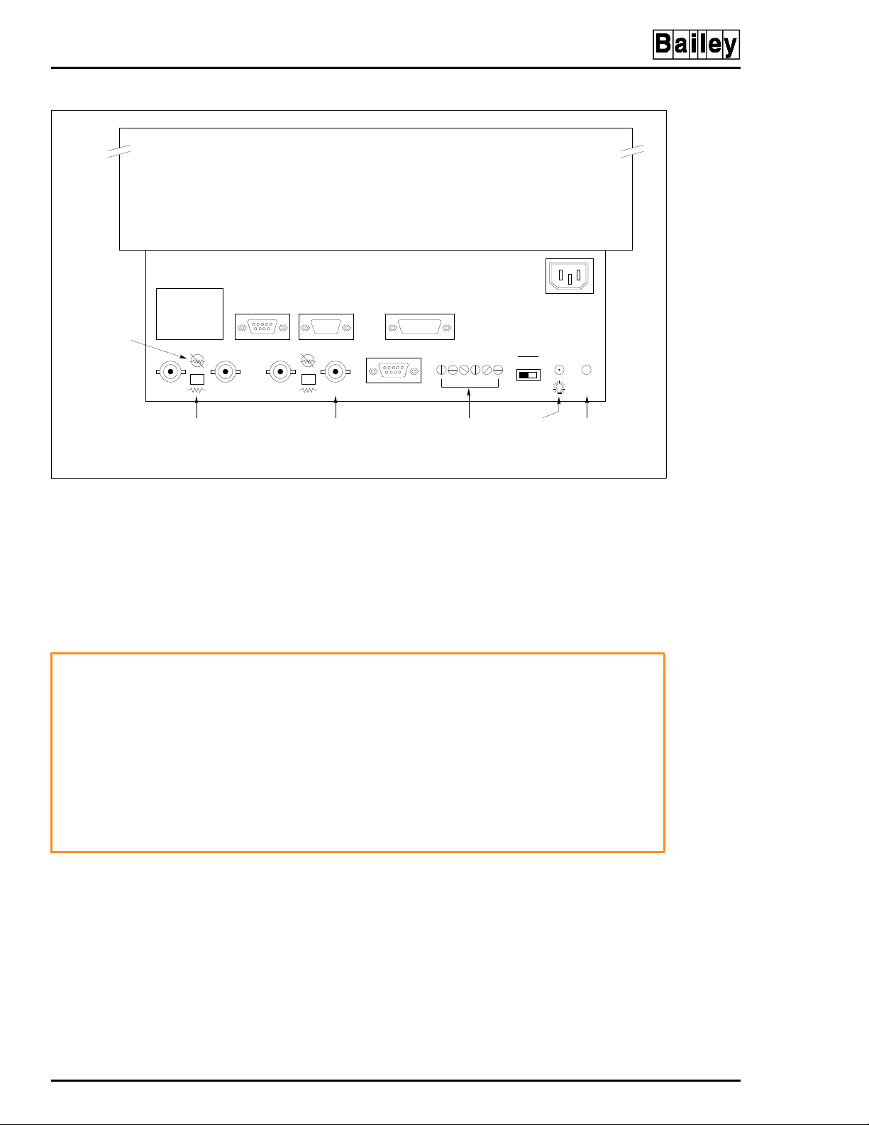
COMPONENT DESCRIPTION AND REPLACEMENT
MONITOR
REMOTE
REMOTE SCREEN
AUX 1
AUX 2
CONTROLS
®
AC
NO RESISTOR
POSITION
WARNING
R
RESISTOR
POSITION
(NOT USED) (NOT USED)(NOT USED)
GBCS DG
COMPOSITE
SYNCH
VGA VGA
SCREEN
ADJUSTMEN TS -
HEIGHT, WIDTH,
BRIGHTNESS,
CONTRAST
SYNC
GRN CS
DEGAUSSPOWER
TP80557A .
Figure 6-16. Color Monitor Connections
2. In the rear of the cabinet, remove the power cord and RGB
cable from the rear of the monitor. Secure the RGB cable out of
the way.
3. The monitor weighs about 27 kg (60 lbs). Be sure it is well
supported.
The monitor will slide out the rear of the cabinet by itself when
the mounting bolts are removed. The monitor weighs approximately 27 kilograms (60 pounds) and can cause bodily injury if
it is allowed to slide out by itself. Support the monitor before
removing the rear two bolts.
Supportez le moniteur avant de retirer les deux boulons
d'ancrange à l'arriér. Lorsque ces boulons d'ancrage sont
AVERTISSEMENT
retirés, l'e moniteur glisser a et sorta à l'arriér de l'armoire. l'e
moniteur pése environ 27 kilograms (60 pounds) et pourrait
entrainer des blessures si on le laisse glisser de l'armoire.
4. Before installing a new monitor, make certain the resistor
switches are set to resistor to insure that the termination is
set for 75 ohms and that the VGA sync switch is set to GRN
(Figure 6-16).
OPERATOR INT ERFACE DEVICES
6 - 22 I-E96-192-5A
Page 86

WARNING
COMPONENT DESCRIPTION AND REPLACEMENT
IIOIC422 CONSOLE MODEL
To remove the monitor from an IIOIC422 console:
1. In the front of the cabinet, turn off the main circuit breaker
on the power entry panel to shut off power to the OIC console.
Check the power indicator to see if power is removed from the
system.
2. In the rear of the cabinet, remove the power cord and RGB
cable from the rear of the monitor. Secure the RGB cable out of
the way.
3. Remove the bolt on each side of the monitor mounting tray
at the rear of the monitor. These bolts attach the tray to the
cabinet shelf.
The monitor will slide out the rear of the cabinet by itself when
the mounting bolts are removed. The monitor weighs approximately 27 kilograms (60 pounds) and can cause bodily injury if
it is allowed to slide out by itself. Support the monitor before
removing the rear two bolts.
AVERTISSEMENT
Supportez le moniteur avant de retirer les deux boulons
d'ancrange à l'arriér. Lorsque ces boulons d'ancrage sont
retirés, l'e moniteur glissera e t sorta à l'arriér de l'armoire. l'e
moniteur pése environ 27 kilograms (60 pounds) et pourrait
entrainer des blessures si on le laisse glisser de l'armoire.
4. Slide the monitor out of the cabinet.
5. After removal, place the monitor and tray onto a solid, flat
surface.
6. Protect the screen of the monitor and set the screen down
on the protective surface.
7. Remove the monitor from the mounting tray by removing
the four screws under the tray.
8. Before installing a new monitor, make certain the resistor
switches are set to resistor to insure that the termination is
set for 75 ohms and that the VGA sync switch is set to GRN
(Figure 6-16).
IIOIC423 ENVIRONMENTAL MODEL
To remove a monitor from an IIOIC423 environmental console:
1. Open the front door and turn off the main circuit breaker
on the power entry panel. Check the power indicator to see if
power is removed.
OPERATOR INTERFACE DEVICES
I-E96-192-5A 6 - 23
Page 87

COMPONENT DESCRIPTION AND REPLACEMENT
2. Label and disconnect all cables going to the back of the
monitor.
3. Open the rear door above the air conditioner. Remove the
two screws fastening the monitor mounting tray to the support
rails.
4. Slide the monitor out of the cabinet. The monitor weighs
about 27 kg (60 lbs). Be sure it is well supported.
5. Before installing a new monitor, make certain the resistor
switches are set to resistor to insure that the termination is
set for 75 ohms and that the VGA sync switch is set to GRN
(Figure 6-16).
IIOIC424 PANEL MOUNTED MODEL
To remove a monitor from an IIOIC424 panel mounted console:
1. Make certain the power to the console is off.
®
2. Refer to Section 3 on panel mount installation for proce-
dures to remove the bezel.
3. Label and disconnect all cables to or from the monitor.
4. Slide the monitor out of the panel. The monitor weighs
about 27 kg (60 lbs). Be sure it is well supported.
5. Before installing a new monitor, make certain the resistor
switches are set to resistor to insure that the termination is
set for 75 ohms and that the VGA sync switch is set to GRN
(Figure 6-16).
MONITOR ASSEMBLY
1. Plug the monitor cable into the monitor port on the back of
the CPU.
2. Connect the red, green and blue cable plugs to the corresponding connectors on the back of the monitor. Use only supplied cables because of length limitations.
3. Plug the monitor power line into the proper socket on the
back of the CPU.
Refer to Section 3 to locate the appropriate cable connection
drawing.
OPERATOR INT ERFACE DEVICES
6 - 24 I-E96-192-5A
Page 88

CPU REMOVAL
COMPONENT DESCRIPTION AND REPLACEMENT
This section contains information and the removal instructions for the CPU inside the OIC consoles. Read the instructions before beginning. Refer to the manufacturer's
documentation for maintenance instructions.
IIOIC421 TABLETOP MODEL
To remove the CPU from an IOIC421 tabletop console see Figure 6-17 and follow these steps.
1. Turn off the power to the console. Check the power indicator to see if power is removed.
2. In the rear of the cabinet, open the access door.
3. Remove the AC power cable from the CPU.
4. Remove and label all communication cables from the rear
of the CPU.
5. Remove the two screws that fasten the CPU mounting plate
to the track on each side of the cabinet.
6. Slide the CPU and mounting plate completely out the rear
of the cabinet.
7. Place the CPU and mounting plate on a clean work surface.
8. Remove the four screws from the bottom of the mounting
plate. These screws fasten the CPU to the mounting plate.
IIOIC422 CONSOLE
To remove the CPU from an IIOIC422 console see Figure 6-18
and follow these steps:
1. Turn off the main circuit breaker on the power entry panel.
Check the power indicator to see if power is removed.
2. Remove and label all cables from the CPU.
3. Remove the two screws that hold the front of the mounting
plate to the shelf.
4. Remove the two screws that hold the rear of the mounting
plate to the support bracket.
5. Slide the CPU and mounting plate out the back of the cabinet.
6. Remove the four screws holding the CPU to the mounting
bracket.
CPU REMOVAL
I-E96-192-5A 6 - 25
Page 89

COMPONENT DESCRIPTION AND REPLACEMENT
KEYBOARD INTERFACE
REAR VIEW OF
MONITOR
ASSEMBLY
®
CPU
MOUSE
PORT
KEYBOARD
PORT
ETHERNET
NETWORK CABLE
CPU MOUNTING PLATE
RETAINING SC R E WS
AUX AC ON/OFF
REAR VIEW (DOORS REMOVED)
Figure 6-17. CPU Removal for IIOIC421
Tabletop Console
POWER
SWIT CH
TP36161C
CPU REMOVAL
6 - 26 I-E96-192-5A
Page 90

COMPONENT DESCRIPTION AND REPLACEMENT
TP36158
D
REAR VIEW
CPU MOUNTING
SCREWS
FRONT VIEW
CPU POW ER ENTRY
PANEL
Figure 6-18. CPU Removal for IIOIC422 Consoles
IIOIC423 ENVIRONMENTAL CABINET
To remove the CPU from an IOIC423 environmental cabinet,
see Figure 6-19 and follow these steps.
1. Open the front door and turn off the main circuit breaker
on the power entry panel to shut off power. Check the power
indicator to see if power is removed.
2. Remove the AC power cable from the CPU.
3. Remove and label all communication cables from the top of
the CPU.
4. Remove the four retaining screws fastening the mounting
plate to the shelf.
5. Slide the mounting plate and CPU out of the cabinet carefully.
6. Remove the four screws that hold the CPU to the mounting
panel.
CPU REMOVAL
I-E96-192-5A 6 - 27
Page 91

COMPONENT DESCRIPTION AND REPLACEMENT
CPU MOUNTING
SCREW S (2)
CPU MOUNTING
SCREW S (2)
®
CPU
TP35499B
Figure 6-19. CPU Removal for IIOIC423
Environmental Console
IIOIC424 PANEL MOUNT
To remove the CPU from an IOIC424 panel mounted model,
see Figure 6-20 and follow these steps.
1. Turn off the main circuit breaker on the power entry panel.
Check the power indicator to see if power is removed.
2. Remove the AC power cable from the CPU.
3. Remove and label all communication cables from the rear
of the CPU.
4. Remove the two screws that hold the CPU to the support
bracket.
5. Slide the unit out along the support bracket.
CPU REMOVAL
6 - 28 I-E96-192-5A
Page 92

COMPONENT DESCRIPTION AND REPLACEMENT
MONITOR
POWER ENTRY PANEL
MOUSE
PORT
KEYBOARD
PORT
ETHERNET
NETWO RK CABLE
CPU
CPU MOUN TING SCREWS
AUX AC ON/OFF
POWER
SWITCH
TP36162D
Figure 6-20. CPU Removal for IIOIC424
Panel Mount Console
CPU ASSEMBLY
When assembling a new CPU, refer to Figure 6-21 for connector callouts and to the appropriate figure in Section 3 for the
cable connections for the model OIC being used.
CPU REMOVAL
I-E96-192-5A 6 - 29
Page 93

COMPONENT DESCRIPTION AND REPLACEMENT
®
MOUSE
PORT
KEYBOARD
PORT
PERIPHERALS
PORT 1
PORT 0 VIDEO PO RT
ETHERNET
NETWORK CABLE
Figure 6-21. CPU Connector Identification
The supported peripherals are portable and require no replacement instructions.
Either an Okidata or Genicom printer connects to port 1 on
the OIC CPU using cable part number 6642555A1. Refer to the
IIOIS42 instruction manual for details on printer configuration, operation and cabling requirements.
NOTE:
or a printer, not both.
Port 1 of the CPU will accept either the touch screen option
AUX
OUT
AC
IN
1
0
ON/OFF
POWER
SWITCH
TP80555A
Refer to the manufacturer's documentation for more information on peripheral devices and for repair information.
PERIPHERALS
6 - 30 I-E96-192-5A
Page 94

SECTION 7 - SUPPORT SERVICES
INTRODUCTION
Bailey Controls Company is always ready to assist in the operation and repair of its products. Send requests for sales or
application services to your nearest sales or service office.
Bailey Controls Company can also provide installation, repair
and maintenance contract services.
REPLACEMENT PARTS AND ORDERING INSTRUCTIONS
Order replacement parts through a Bailey Controls Company
sales or service office. Provide the following information when
ordering parts:
1. Part description, part number and quantity.
2. Model and serial number (if applicable) and ratings of the
assembly the part has been ordered for.
3. Publication number and reference used in identifying the
part.
When ordering parts, use part numbers and part descriptions
from equipment manuals. Parts with no commercial description must be ordered from your nearest sales or service office.
Recommended spare parts lists, including prices, on standard
assemblies are available through your nearest sales or service
office.
TRAINING
Bailey Controls Company has a modern training facility available for training your personnel. On-site training is also available. Contact a Bailey Controls Company sales office for
specific information and scheduling.
TECHNICAL DOCUMENTATION
Price and delivery of additional copies of this publication can
be obtained through your nearest sales or service office.
SPARE PARTS
Spare parts Table 7-1 lists the recommended spare parts for
the IIOIC42 operator interface. Bailey Controls Company suggests stocking one item each to minimize the duration and cost
of downtime.
INTRODUCTION
I-E96-192-5A 7 - 1
Page 95

SUPPORT SERVICES
Table 7-1. Recommended Spare Parts
®
Description
50-ohm ThinWire terminator 1949009A1 x x x x
Annunciator display panel IIADP02 x
Annunciator display panel NADS03 x
CPU - Tektronics, model
XP400
Fan 11.43 cm (4-1/2 in) 1947419A7 x
Fan assembly (3-inch) 6640639A1 x
Fuse 2 A, 250V fast acting
(keyboard interface board)
Fuse 1 A (keyboard interface
front panel - IIOIC421)
Joystick 1948803A2 x
Keyboard enclosure 1948802A3 x
Keyboard, operator (mylar) 6638514A1 x x x
Keyboard, operator (mylar) 6638514A2 x
Keyboard, QWERTY
(auxiliary engineering)
Monitor (19-inch) 1948623A9 x x x x
Monitor brightness cable
(lower monitor) IIOIC4221
Monitor brightness cable
(upper monitor) IIOIC4222
Monitor brightness cable (all
others)
Mouse IIAMS04 x x x
Multibus keyboard modul e IIMKM02A x x x x
Power entry panel 6638353M5 x
Power entry panel 6639503A5 x
Power entry panel 6640851A2 x
Power supply 6638553A5 x
Power supply 6640038A1 x x x
Nomenclature or
Part Number
6642485A1 x x x x
1948182A22001 x x x x
194776A11001xxxx
IIAKB04 x x x x
6638720A4 x x x
6638720A5 x
6638720A6 x x x
421 422 423 424
OIC
SPARE PARTS
7 - 2 I-E96-192-5A
Page 96
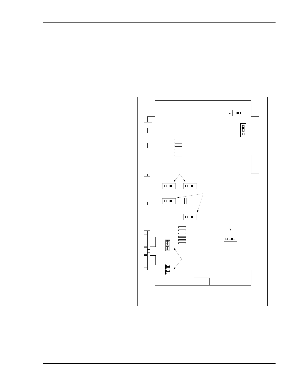
APPENDIX A - QUICK REFERENCE INFORMATION
INTRODUCTION
This section provides a source for reference information. It
contains the jumper and switch settings and fuse locations for
the OIC42 operator interface console.
P3
P4
P5
P6
P7
P8
P9
1-2 DISABLE OOT SIGNAL
2-3 ENABLE OOT SIGNAL
P15
NOT USED
J9 J7
123
J8
123
P14
J2
J1
123
P17
J6
123
P18
CONNECT 8 PINS VERTICALLY - DATA
TRANSMITTED FROM PIN 2, RECEIVED
ON PIN3.
CONNECT 8 PINS HORIZONTALLY DATA TRANSMITTED FROM PIN 3,
RECEIVED ON PIN 2.
J4
123
NOT
USED
3
2
1
J5
2-3 TOUCH SCREEN USE
1-2 RESET ON TIME-OUT
2-3 NO RESET ON TIME-OUT
J3
123
P16
POWER CONNECTOR FOR
IIMKM02A WHEN USED ON TH E
IIOIC421, IIOIC 42 3 AND IIOIC4 2 4.
NOT U S E D IN IIOIC422.
TP80571A
Figure A-1. IIMKM02A Multibus Keyboard Module
INTRODUCTION
I-E96-192-5A A - 1
Page 97

QUICK REFERENCE INFORMATION
TO P5 O N
MKM BOARD
P1
TO P7 O N
MKM BOARD
AND TO P2 ON
ADP BOARD
P8
ASSY 6638238-1
P3
J2
1
2
BLU
RED
YEL
VIO
BRN
BLK
J1
F1 F3
F2
P4
PORT ON CPU
SW1 SW ITCHES
5,6AND7ARE
CLOSED (ON)
SW1
TO MO USE
P10
P5
GND
+12V
-12V
5V
NOT USED
P9
P2
TP P3 ON DC
DISTRIBUTION
BOARD. NOT USED ON
IIOIC 421 OR IIO IC424.
F1, F2 A ND F3
ARE 2-A, 25 0 -V
P6
FAST BLOW
CAUTION: SW ITCHES 5, 6
AND 7 ARE CLO SED (ON).
SWITCHES 1 THRO UGH 4
AND 8 ARE OPEN (OFF). IF
THEY ARE NOT SET
CORRECTLY, DAMAGE TO
THE CPU MAY RESULT.
®
KEYBOARD
AUX 1 PORT
MOUSE/TRACKBALL
AUX KBD
Figure A-2. Keyboard Interface Connector Board
TO
CPU
AC IN AC OUT
TO KEYBO ARD
PORT
TO
COMMUNICATION
PORT
J1
J2
J5
FUSE F1
1AMP
J4
F1
R G B RESET DEGAU SS
J3
TO MOUSE
PORT
2
NO
1
NO
Figure A-3. IIOIC421 Keyboard Interface Assembly
TP80570A
WRIST
STRAP
2
4
2
4
NC
CO
NO
1
1
3
NC
CO
NO
6
4
6CODI
DO
DI
6
NC
NC
CO
NO
3
5
3
5
5
NC
NC
CO
CO
NO
DO
2+
2+
2–
2–
DI
DI
DO
DO
1+
1–
1+
1–
TP80569A
INTRODUCTION
A - 2 I-E96-192-5A
Page 98

Ω
A
.
REMOTE
AUX 1
AUX 2
QUICK REFERENCE INFORMATION
MONITOR
REMOTE SCREEN
CONTROLS
AC
NO RESISTOR
POSITION
R
RESISTOR
POSITION
(NOT USED) (NOT U SE D)(NOT USED)
GBCS DG
RESISTOR
SWITCHES FOR
75- TERMINATION
COMPOSITE
SYNCH
VGA VGA
SCREEN
ADJUSTMENTS HEIGHT,W IDTH,
BRIGHTNESS,
CONTRAST
SYNC
GRN CS
SYNCH ON
GREEN SWITCH
Figure A-4. Color Monitor
S1
1234
OPEN
S2
12345678
OPEN
DEGAUSSPOWER
TP80574
1
TOUCH SCREEN
CABLE
5
R3
NOT USED
CONNECTOR
PINS PLUG INTO
MKM BOARD
S1
S2
TP80572A .
Figure A-5. Touch Screen Controller Board
INTRODUCTION
I-E96-192-5A A - 3
Page 99

QUICK REFERENCE INFORMATION
ADDRESS SWITCH
12345678
NOTE:
LOCATION OF SW 1 ON PC BOARD W ILL
VARYACCORDING TO ADP/ADS USE.
SW1 SETTING FO R SINGLE DISPLAY
SAME FOR ALL UNITS.
SETTINGS
SW1
OPEN
ADP
1
BACK OF
ADP PANEL
ADDRESS
SWITCH
PC BOARD
®
SW1
TP80573A .
ADDRESS SW ITCH
SETTINGS
12345678
SW1
OPEN
12345678
SW1
OPEN
12345678
SW1
OPEN
12345678
SW1
OPEN
BACK OF
ADP PANEL
ADDRESS
SWITCH
PC BOARD
ADP
1
ADP
2
ADP
3
ADP
4
TO AUX P ORT ON
KEYBOARD
INTERFACE BOARD
Figure A-6. IIADP01, IIADP02 and NADS03
12345678
SW1
OPEN
ADP
2
P1
P2
ADP
3
P2 P2
P1
1948978A1
ADP
4
P1
TP35494B .
Figure A-7. IIADP01 Multiple Annunciator Displays
INTRODUCTION
A - 4 I-E96-192-5A
Page 100

Index
A
AC power.................................................................... 3-4
240 VAC ......................................................... ..... .3-4
Test................................................ ..... ...... ...... ..... .4-2
Wiring............................ ....................3-12, 3-17, 3-21
Annunciator display panel
Connections........................................................ 3-25
IIADP01 .............................................................. 3-24
IIADP02 .............................................................. 3-25
NADS03.............................................................. 3-26
C
Cabling
IIOIC421............................................................... 3-6
IIOIC422............................................................. 3-12
IIOIC423............................................................. 3-17
IIOIC424............................................................. 3-21
Check list, maintenance.............................................5-1
Checking
Power entry panel................................................. 5-6
Power supply outputs........................................... 5-5
Circuit board cleaning.................................................5-4
Cleaning
Engineering keyboard........................................... 5-4
Monitor.................................................................. 5-3
Mylar keyboard.....................................................5-4
Operator keyboard................................................ 5-4
Printed circuit boards............................................5-4
Qwerty keyboard................................................... 5-4
Console......................................................................6-5
Power entry panel.............................6-10, 6-11, 6-13
Power supply.............................6-8, 6-11, 6-12, 6-13
Wiring..................................................................3-12
CPU connector identification....................................6-30
CPU removal...................................................6-26, 6-28
IIOIC42............................................................... 6-25
IIOIC42 Console.................................................6-25
IIOIC421............................................................. 6-25
IIOIC422............................................................. 6-25
IIOIC423............................................................. 6-27
IIOIC424............................................................. 6-28
D
DC power test............................................................. 4-3
Diagnostic power up tests.......................................... 4-2
Environmental cabinet, wiring...................................3-17
F
Fan assembly, card cage............................................6-5
Functional operation, OIC...........................................2-2
Fuses
F1 keyboard interface front panel .........................3-7
F1, F2, F3 keyboard interface board...................6-18
H
Handling, OIC.............................................................3-1
Hardware, nomenclature.............................................1-7
I
IIADP01 annunciator display panel...........................3-24
IIADP02 annunciator display panel...........................3-25
IIAKB04 engineering keyboard.................................3-21
IIAMS04/IIATB05 trackball/mouse............................3-24
IIATB05/IIAMS04 trackball/mouse............................3-24
IIIMKM02A..................................................................6-1
IIOIC42 models........................................................... 1-4
IIOIC421
Cable connections.................................................3-8
Cabling..................................................................3-6
Setup and installation............................................3-6
Wiring....................................................................3-6
IIOIC422
Cable connections...............................................3-14
Console multibus card cage..................................6-4
Setup and installation............................................3-6
Wiring..................................................................3-12
IIOIC423
Cable connections...............................................3-18
Setup and installation.................................3-15, 3-16
Wiring..................................................................3-17
IIOIC424
Cable connections...............................................3-22
Component locations..........................................3-20
Setup and installation..........................................3-20
Wiring..................................................................3-21
Inspection and unpacking...........................................3-2
Installation procedure...........................................3-3, 3-5
Intended user..............................................................1-1
J
E
Engineering keyboard.............................................. 3-21
Cleaning................................................................ 5-4
Jumpers, J1-J9 IIMKM02A..........................................6-2
I-E96-192-5A Index - 1
 Loading...