


© 2015 Baileigh Industrial, Inc.
REPRODUCTION OF THIS MANUAL IN ANY FORM WITHOUT WRITTEN APPROVAL OF BAILEIGH INDUSTRIAL, INC.
IS PROHIBITED. Baileigh Industrial, Inc. does not assume and hereby disclaims any liability for any damage or loss
caused by an omission or error in this Operator’s Manual, resulting from accident, negligence, or other occurrence.
Rev. 04/2015
Baileigh Industrial, Inc.
P.O. Box 531
Manitowoc, WI 54221-0531
Phone: 920.684.4990
Fax: 920.684.3944
sales@baileighindustrial.com
OPERATOR’S MANUAL
TUBE AND PIPE NOTCHER
MODEL: TN-400

Table of Contents
THANK YOU & WARRANTY .......................................................................................... 1
INTRODUCTION ............................................................................................................. 3
GENERAL NOTES .......................................................................................................... 3
SAFETY INSTRUCTIONS .............................................................................................. 4
SAFETY PRECAUTIONS ............................................................................................... 6
TECHNICAL SPECIFICATIONS ..................................................................................... 8
TECHNICAL SUPPORT ................................................................................................. 8
UNPACKING AND CHECKING CONTENTS .................................................................. 9
Cleaning ...................................................................................................................... 9
TRANSPORTING AND LIFTING .................................................................................. 10
INSTALLATION ............................................................................................................. 10
ASSEMBLY AND SET UP ............................................................................................ 11
ELECTRICAL ................................................................................................................ 12
Plug Connection ........................................................................................................ 13
OPERATION ................................................................................................................. 14
Mandrel / Belt Selection and Installation .................................................................... 14
Material Insertion ....................................................................................................... 15
Notching .................................................................................................................... 16
MATERIAL SELECTION ............................................................................................... 17
STANDARD PIPE SIZES AND SCHEDULES TABLE .................................................. 17
ELECTRICAL SCHEMATIC .......................................................................................... 18
LUBRICATION AND MAINTENANCE .......................................................................... 19
Oil Disposal ............................................................................................................... 19
Storing Machine for Extended Period of Time ........................................................... 19
PARTS DIAGRAM ........................................................................................................ 20
Main Tube Assembly ................................................................................................. 20
Slide Assembly .......................................................................................................... 21
Vise Assembly ........................................................................................................... 22
Mandrel Holder Assembly ......................................................................................... 23
Guard Assembly ........................................................................................................ 24
Motor Assembly ......................................................................................................... 25
Tension Adjustment Assembly .................................................................................. 26
Parts List ................................................................................................................... 27

1
1
THANK YOU & WARRANTY
Thank you for your purchase of a machine from Baileigh Industrial. We hope that you find it
productive and useful to you for a long time to come.
Inspection & Acceptance. Buyer shall inspect all Goods within ten (10) days after receipt thereof. Buyer’s
payment shall constitute final acceptance of the Goods and shall act as a waiver of the Buyer’s rights to inspect or
reject the goods unless otherwise agreed. If Buyer rejects any merchandise, Buyer must first obtain a Returned
Goods Authorization (“RGA”) number before returning any goods to Seller. Goods returned without a RGA will be
refused. Seller will not be responsible for any freight costs, damages to goods, or any other costs or liabilities
pertaining to goods returned without a RGA. Seller shall have the right to substitute a conforming tender. Buyer will
be responsible for all freight costs to and from Buyer and repackaging costs, if any, if Buyer refuses to accept
shipment. If Goods are returned in unsalable condition, Buyer shall be responsible for full value of the Goods.
Buyer may not return any special order Goods. Any Goods returned hereunder shall be subject to a restocking fee
equal to 30% of the invoice price.
Specifications. Seller may, at its option, make changes in the designs, specifications or components of the Goods
to improve the safety of such Goods, or if in Seller’s judgment, such changes will be beneficial to their operation or
use. Buyer may not make any changes in the specifications for the Goods unless Seller approves of such changes
in writing, in which event Seller may impose additional charges to implement such changes.
Limited Warranty. Seller warrants to the original end-user that the Goods manufactured or provided by Seller
under this Agreement shall be free of defects in material or workmanship for a period of twelve (12) months from
the date of purchase, provided that the Goods are installed, used, and maintained in accordance with any
instruction manual or technical guidelines provided by the Seller or supplied with the Goods, if applicable. The
original end-user must give written notice to Seller of any suspected defect in the Goods prior to the expiration of
the warranty period. The original end-user must also obtain a RGA from Seller prior to returning any Goods to
Seller for warranty service under this paragraph. Seller will not accept any responsibility for Goods returned without
a RGA. The original end-user shall be responsible for all costs and expenses associated with returning the Goods
to Seller for warranty service. In the event of a defect, Seller, at its sole option, shall repair or replace the defective
Goods or refund to the original end-user the purchase price for such defective Goods. Goods are not eligible for
replacement or return after a period of 30 days from date of receipt. The foregoing warranty is Seller’s sole
obligation, and the original end-user’s exclusive remedy, with regard to any defective Goods. This limited warranty
does not apply to: (a) die sets, tooling, and saw blades; (b) periodic or routine maintenance and setup, (c) repair or
replacement of the Goods due to normal wear and tear, (d) defects or damage to the Goods resulting from misuse,
abuse, neglect, or accidents, (f) defects or damage to the Goods resulting from improper or unauthorized
alterations, modifications, or changes; and (f) any Goods that has not been installed and/or maintained in
accordance with the instruction manual or technical guidelines provided by Seller.
EXCLUSION OF OTHER WARRANTIES. THE FOREGOING LIMITED WARRANTY IS IN LIEU OF ALL OTHER
WARRANTIES, EXPRESS OR IMPLIED. ANY AND ALL OTHER EXPRESS, STATUTORY OR IMPLIED
WARRANTIES, INCLUDING BUT NOT LIMITED TO, ANY WARRANTY OF MERCHANTABILITY OR FITNESS
FOR ANY PARTICULAR PURPOSE ARE EXPRESSLY DISCLAIMED. NO WARRANTY IS MADE WHICH
EXTENDS BEYOND THAT WHICH IS EXPRESSLY CONTAINED HEREIN.
Limitation of Liability. IN NO EVENT SHALL SELLER BE LIABLE TO BUYER OR ANY OTHER PARTY FOR
ANY INCIDENTIAL, CONSEQUENTIAL OR SPECIAL DAMAGES (INCLUDING, WITHOUT LIMITATION, LOST
PROFITS OR DOWN TIME) ARISING FROM OR IN MANNER CONNECTED WITH THE GOODS, ANY BREACH
BY SELLER OR ITS AGENTS OF THIS AGREEMENT, OR ANY OTHER CAUSE WHATSOEVER, WHETHER
BASED ON CONTRACT, TORT OR ANY OTHER THEORY OF LIABILITY. BUYER’S REMEDY WITH RESPECT
TO ANY CLAIM ARISING UNDER THIS AGREEMENT IS STRICTLY LIMITED TO NO MORE THAN THE
AMOUNT PAID BY THE BUYER FOR THE GOODS.

2
2
Force Majuere. Seller shall not be responsible for any delay in the delivery of, or failure to deliver, Goods due to
causes beyond Seller’s reasonable control including, without limitation, acts of God, acts of war or terrorism, enemy
actions, hostilities, strikes, labor difficulties, embargoes, non-delivery or late delivery of materials, parts and
equipment or transportation delays not caused by the fault of Seller, delays caused by civil authorities,
governmental regulations or orders, fire, lightening, natural disasters or any other cause beyond Seller's reasonable
control. In the event of any such delay, performance will be postponed by such length of time as may be reasonably
necessary to compensate for the delay.
Installation. If Buyer purchases any Goods that require installation, Buyer shall, at its expense, make all
arrangements and connections necessary to install and operate the Goods. Buyer shall install the Goods in
accordance with any Seller instructions and shall indemnify Seller against any and all damages, demands, suits,
causes of action, claims and expenses (including actual attorneys’ fees and costs) arising directly or indirectly out
of Buyer’s failure to properly install the Goods.
Work By Others; Safety Devices. Unless agreed to in writing by Seller, Seller has no responsibility for labor or
work performed by Buyer or others, of any nature, relating to design, manufacture, fabrication, use, installation or
provision of Goods. Buyer is solely responsible for furnishing, and requiring its employees and customers to use all
safety devices, guards and safe operating procedures required by law and/or as set forth in manuals and instruction
sheets furnished by Seller. Buyer is responsible for consulting all operator’s manuals, ANSI or comparable safety
standards, OSHA regulations and other sources of safety standards and regulations applicable to the use and
operation of the Goods.
Remedies. Each of the rights and remedies of Seller under this Agreement is cumulative and in addition to any
other or further remedies provided under this Agreement or at law or equity.
Attorney’s Fees. In the event legal action is necessary to recover monies due from Buyer or to enforce any
provision of this Agreement, Buyer shall be liable to Seller for all costs and expenses associated therewith,
including Seller’s actual attorneys' fees and costs.
Governing Law/Venue. This Agreement shall be construed and governed under the laws of the State of
Wisconsin, without application of conflict of law principles. Each party agrees that all actions or proceedings arising
out of or in connection with this Agreement shall be commenced, tried, and litigated only in the state courts sitting in
Manitowoc County, Wisconsin or the U.S. Federal Court for the Eastern District of Wisconsin. Each party waives
any right it may have to assert the doctrine of “forum non conveniens” or to object to venue to the extent that any
proceeding is brought in accordance with this section. Each party consents to and waives any objection to the
exercise of personal jurisdiction over it by courts described in this section. Each party waives to the fullest extent
permitted by applicable law the right to a trial by jury.
Summary of Return Policy.
10 Day acceptance period from date of delivery. Damage claims and order discrepancies will not be accepted
after this time.
You must obtain a Baileigh issued RGA number PRIOR to returning any materials.
Returned materials must be received at Baileigh in new condition and in original packaging.
Altered items are not eligible for return.
Buyer is responsible for all shipping charges.
A 30% re-stocking fee applies to all returns.
Baileigh Industrial makes every effort to ensure that our posted specifications, images, pricing and product
availability are as correct and timely as possible. We apologize for any discrepancies that may occur. Baileigh
Industrial reserves the right to make any and all changes deemed necessary in the course of business including but
not limited to pricing, product specifications, quantities, and product availability.
For Customer Service & Technical Support:
Please contact one of our knowledgeable Sales and Service team members at:
(920) 684-4990 or e-mail us at sales@baileighindustrial.com

3
3
INTRODUCTION
The quality and reliability of the components assembled on a Baileigh Industrial machine
guarantee near perfect functioning, free from problems, even under the most demanding
working conditions. However if a situation arises, refer to the manual first. If a solution cannot be
found, contact the distributor where you purchased our product. Make sure you have the serial
number and production year of the machine (stamped on the nameplate). For replacement parts
refer to the assembly numbers on the parts list drawings.
Our technical staff will do their best to help you get your machine back in working order.
In this manual you will find: (when applicable)
Safety procedures
Correct installation guidelines
Description of the functional parts of the machine
Capacity charts
Set-up and start-up instructions
Machine operation
Scheduled maintenance
Parts lists
GENERAL NOTES
After receiving your equipment remove the protective container. Do a complete visual
inspection, and if damage is noted, photograph it for insurance claims and contact your
carrier at once, requesting inspection. Also contact Baileigh Industrial and inform them of the
unexpected occurrence. Temporarily suspend installation.
Take necessary precautions while loading / unloading or moving the machine to avoid any
injuries.
Your machine is designed and manufactured to work smoothly and efficiently. Following proper
maintenance instructions will help ensure this. Try and use original spare parts, whenever
possible, and most importantly; DO NOT overload the machine or make any unauthorized
modifications.
Note: This symbol refers to useful information throughout the manual.

4
4
LEARN TO RECOGNIZE SAFETY INFORMATION
IMPORTANT
PLEASE READ THIS OPERATORS MANUAL CAREFULLY
It contains important safety information, instructions, and necessary operating
procedures. The continual observance of these procedures will help increase your
production and extend the life of the equipment.
SAFETY INSTRUCTIONS
This is the safety alert symbol. When you see this symbol on
your machine or in this manual, BE ALERT TO THE
POTENTIAL FOR PERSONAL INJURY!
Follow recommended precautions and safe operating
practices.
UNDERSTAND SIGNAL WORDS
A signal word – DANGER, WARNING, or CAUTION
is used with the safety alert symbol. DANGER
identifies a hazard or unsafe practice that will result in
severe Injury or Death.
Safety signs with signal word DANGER or WARNING are
typically near specific hazards.
General precautions are listed on CAUTION safety signs.
CAUTION also calls attention to safety messages in this
manual.

5
5
SAVE THESE INSTRUCTIONS.
Refer to them often and use them to instruct others.
PROTECT EYES
Wear safety glasses or suitable eye protection
when working on or around machinery.
PROTECT AGAINST NOISE
Prolonged exposure to loud noise can cause impairment or loss of
hearing. Wear suitable hearing protective devices such as ear muffs or
earplugs to protect against objectionable or uncomfortable loud noises.
BEWARE OF PINCH POINTS
Keep hands and fingers away from the slide plate and pivot points
when operating on and around this machine. Keep guard in place at
all times while the machine is running.
ENTANGLEMENT HAZARD – ROTATING SPINDLE
Contain long hair, DO NOT wear jewelry or loose fitting clothing.
MOVING BELT ABRASIONS
DO NOT place hands or fingers near, or in contact with sanding belt
during operation.

6
6
SAFETY PRECAUTIONS
WARNING: FAILURE TO FOLLOW THESE RULES MAY RESULT IN
SERIOUS PERSONAL INJURY
Metal working can be dangerous if safe and proper operating procedures are not followed. As
with all machinery, there are certain hazards involved with the operation of the product. Using
the machine with respect and caution will considerably lessen the possibility of personal injury.
However, if normal safety precautions are overlooked or ignored, personal injury to the operator
may result.
Safety equipment such as guards, hold-downs, safety glasses, dust masks and hearing
protection can reduce your potential for injury. But even the best guard won’t make up for poor
judgment, carelessness or inattention. Always use common sense and exercise caution in
the workshop. If a procedure feels dangerous, don’t try it.
REMEMBER: Your personal safety is your responsibility.
1. Only trained and qualified personnel can operate this machine.
2. Make sure guards are in place and in proper working order before operating
machinery.
3. Remove any adjusting tools. Before operating the machine, make sure any adjusting tools
have been removed.
4. Keep work area clean. Cluttered areas invite injuries.
5. Overloading machine. By overloading the machine you may cause injury from flying parts.
DO NOT exceed the specified machine capacities.
6. Dressing material edges. Always chamfer and deburr all sharp edges.
7. Do not force tool. Your machine will do a better and safer job if used as intended. DO NOT
use inappropriate attachments in an attempt to exceed the machines rated capacity.
8. Use the right tool for the job. DO NOT attempt to force a small tool or attachment to do the
work of a large industrial tool. DO NOT use a tool for a purpose for which it was not
intended.
9. Dress appropriate. DO NOT wear loose fitting clothing or jewelry as they can be caught in
moving machine parts. Protective clothing and steel toe shoes are recommended when
using machinery. Wear a restrictive hair covering to contain long hair.
10. Use eye and ear protection. Always wear ISO approved impact safety goggles. Wear a full-
face shield if you are producing metal filings.

7
7
11. Do not overreach. Maintain proper footing and balance at all times. DO NOT reach over or
across a running machine.
12. Stay alert. Watch what you are doing and use common sense. DO NOT operate any tool or
machine when you are tired.
13. Check for damaged parts. Before using any tool or machine, carefully check any part that
appears damaged. Check for alignment and binding of moving parts that may affect proper
machine operation.
14. Observe work area conditions. DO NOT use machines or power tools in damp or wet
locations. Do not expose to rain. Keep work area well lighted. DO NOT use electrically
powered tools in the presence of flammable gases or liquids.
15. Blade adjustments and maintenance. Always keep blades sharp and properly adjusted for
optimum performance.
16. Keep children away. Children must never be allowed in the work area. DO NOT let them
handle machines, tools, or extension cords.
17. Store idle equipment. When not in use, tools must be stored in a dry location to inhibit rust.
Always lock up tools and keep them out of reach of children.
18. DO NOT operate machine if under the influence of alcohol or drugs. Read warning labels
on prescriptions. If there is any doubt, DO NOT operate the machine.
19. DO NOT touch live electrical components or parts.
20. Turn off power before checking, cleaning, or replacing any parts.
21. Be sure all equipment is properly installed and grounded according to national, state, and
local codes.
22. Inspect power and control cables periodically. Replace if damaged or bare wires are
exposed. Bare wiring can kill!
23. DO NOT bypass or defeat any safety interlock systems.
24. Keep visitors a safe distance from the work area.

8
8
Notching Capacity (OD)
.75" - 2" (19 – 51mm)
Angle Adjustment
0 – 60°
Belt Size
4" x 79" (101 x 2007mm)
Belt Speed
5420fpm (1652mpm)
Power
220V / 1ph / 60hz / 20A
Motor
3hp (2.25kw)
Shipping Weight
450lbs. (205kgs)
Shipping Dimensions
60" x 44" x 60" (1524 x 1118 x 1524mm)
TECHNICAL SPECIFICATIONS
TECHNICAL SUPPORT
Our technical support department can be reached at 920.684.4990, and asking for the support
desk for purchased machines. Tech Support handles questions on machine setup, schematics,
warranty issues, and individual parts needs: (other than die sets and blades).
For specific application needs or future machine purchases contact the Sales Department at:
sales@baileighindustrial.com, Phone: 920.684.4990, or Fax: 920.684.3944.
Note: The photos illustrations used in this manual are representative only and may
not depict the actual color, labeling or accessories and may be intended to illustrate technique
only.
Note: The specifications and dimensions presented here are subject to change
without prior notice due to improvements of our products.

9
9
WARNING: SUFFOCATION HAZARD! Immediately discard any plastic
bags and packing materials to eliminate choking and suffocation hazards to children
and animals.
If any parts are missing, do not plug in the power cable, or turn the power switch on
until the missing parts are obtained and installed correctly.
WARNING: DO NOT USE gasoline or other petroleum products to clean
the machine. They have low flash points and can explode or cause fire.
CAUTION: When using cleaning solvents work in a well-ventilated area.
Many cleaning solvents are toxic if inhaled.
GAS
UNPACKING AND CHECKING CONTENTS
Your Baileigh machine is shipped complete in one crate. Separate all parts from the packing
material and check each item carefully. Make certain all items are accounted for before
discarding any packing material.
Cleaning
Your machine may be shipped with a rustproof waxy oil coating and grease on the exposed
unpainted metal surfaces. To remove this protective coating, use a degreaser or solvent
cleaner. For a more thorough cleaning, some parts will occasionally have to be removed. DO
NOT USE acetone or brake cleaner as they may damage painted surfaces.
Follow manufacturer’s label instructions when using any type of cleaning product. After cleaning,
wipe unpainted metal surfaces with a light coating of quality oil or grease for protection.
10
10
TRANSPORTING AND LIFTING
IMPORTANT: Lifting and carrying operations should be carried out by skilled workers,
such as a truck operator, crane operator, etc. If a crane is used to lift the machine, attach the
lifting chain carefully, making sure the machine is well balanced.
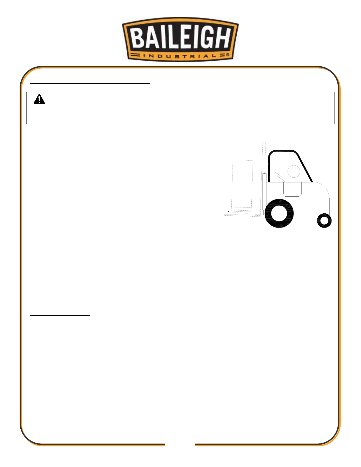
Follow these guidelines when lifting with truck or trolley:
The lift truck must be able to lift at least 1.5 – 2 times
the machines gross weight.
Make sure the machine is balanced. While
transporting, avoid rough or jerky motion, and maintain
a safe clearance zone around the transport area.
Use a fork lift with sufficient lifting capacity and forks
that are long enough to reach the complete width of
the machine.
Remove the securing bolts that attach the machine to
the pallet.
Approaching the machine from the side, lift the machine on the frame taking care that there
are no cables or pipes in the area of the forks.
Move the machine to the required position and lower gently to the floor.
Level the machine so that all the supporting feet are taking the weight of the machine and no
rocking is taking place.
INSTALLATION
IMPORTANT:
Consider the following when looking for a suitable location to place the machine:
Overall weight of the machine.
Weight of material being processed.
Sizes of material to be processed through the machine.
Space needed for auxiliary stands, work tables, or other machinery.
Clearance from walls and other obstacles.
Maintain an adequate working area around the machine for safety.
Have the work area well illuminated with proper lighting.
Keep the floor free of oil and make sure it is not slippery.

11
11
WARNING: For your own safety, DO NOT connect the machine to the
power source until the machine is completely assembled and you read and
understand the entire instruction manual.
Remove scrap and waste materials regularly, and make sure the work area is free from
obstructing objects.
If long lengths of material are to be fed into the machine, make sure that they will not extend
into any aisles.
LEVELING: The machine should be sited on a level, concrete floor. Provisions for securing it
should be in position prior to placing the machine. The accuracy of any machine depends on
the precise placement of it to the mounting surface.
FLOOR: This tool distributes a large amount of weight over a small area. Make certain that
the floor is capable of supporting the weight of the machine, work stock, and the operator.
The floor should also be a level surface. If the unit wobbles or rocks once in place, be sure to
eliminate by using shims.
WORKING CLEARANCES: Take into consideration the size of the material to be
processed. Make sure that you allow enough space for you to operate the machine freely.
POWER SUPPLY PLACEMENT: The power supply should be located close enough to the
machine so that the power cord is not in an area where it would cause a tripping hazard. Be
sure to observe all electrical codes if installing new circuits and/or outlets.
ASSEMBLY AND SET UP
1. Remove the machine from the skid it was shipped on and install the casters.
2. Check the oil level and top off if necessary.
3. Read through the remainder of the manual and become familiar with the tool installation and
settings as well as normal operation.
4. Position the machine as desired following the installation guidelines.
5. Follow the electrical guidelines to connect the machine to a power supply.

12
12
CAUTION: HAVE ELECTRICAL UTILITIES CONNECTED TO MACHINE BY
A CERTIFIED ELECTRICIAN!
Check if the available power supply is the same as listed on the machine nameplate.
WARNING: Make sure the grounding wire (green) is properly connected
to avoid electric shock. DO NOT switch the position of the green grounding wire if
any electrical plug wires are switched during hookup.
WARNING: In all cases, make certain the receptacle in question is
properly grounded. If you are not sure, have a qualified electrician check the
receptacle.
ELECTRICAL
Motor Specifications
Your tool is wired for 220 volt, 60Hz alternating current. Before connecting the tool to the power
source, make sure the machine is cut off from power source.
Considerations
Observe local electrical codes when connecting the machine.
The circuit should be protected with a time delay fuse or circuit breaker with a amperage
rating slightly higher than the full load current of machine.
A separate electrical circuit should be used for your tools. Before connecting the motor to the
power line, make sure the switch is in the “OFF” position and be sure that the electric current
is of the same characteristics as indicated on the tool.
All line connections should make good contact. Running on low voltage will damage the
motor.
In the event of a malfunction or breakdown, grounding provides a path of least resistance for
electric current to reduce the risk of electric shock. This tool is equipped with an electric cord
having an equipment-grounding conductor and a grounding plug. The plug must be plugged
into a matching outlet that is properly installed and grounded in accordance with all local
codes and ordinances.

13
13
LENGTH
AMP RATING
25ft
50ft
100ft
0-6
16
16
16
7-10
16
16
14
11-12
16
16
14
13-16
14
12
12
17-20
12
12
10
21-30
10
10
No WIRE GAUGE
Improper connection of the equipment-grounding conductor can result in risk of electric
shock. The conductor with insulation having an outer surface that is green with or without
yellow stripes is the equipment-grounding conductor. If repair or replacement of the electric
cord or plug is necessary, do not connect the equipment-grounding conductor to a live
terminal.
Check with a qualified electrician or service personnel if the grounding instructions are not
completely understood, or if in doubt as to whether the tool is properly grounded.
Repair or replace damaged or worn cord immediately.
Extension Cord Safety
Extension cord should be in good condition and meet the minimum wire gauge requirements
listed below:
An undersized cord decreases line voltage, causing loss of power and overheating. All cords
should use a ground wire and plug pin. Replace any damaged cords immediately.
Plug Connection
Have an electrician install the correct power supply for the application.
Once hooked up, turn on the power supply and start the machine.
14
14
CAUTION: Always wear proper eye protection with side shields, safety
footwear, and leather gloves to protect from burrs and sharp edges.
WARNING: BEFORE THE MAIN LEXAN GUARD IS OPENED, THE
POWER CORD MUST BE UNPLUGGED FROM ITS SOURCE.
A
C
D
OPERATION
Mandrel / Belt Selection and Installation
1. Before any notching can take place, the
proper mandrel must be chosen. The
material size is stamped or marked on each
mandrel’s end.
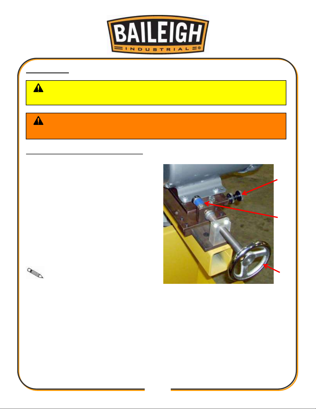
2. To install a Mandrel, first unplug the power
cord and open the main Lexan guard.
3. Loosen the belt tension handwheel (A) until
the belt is loose.
4. Grab the mandrel and lift it out of the bearing
saddles.
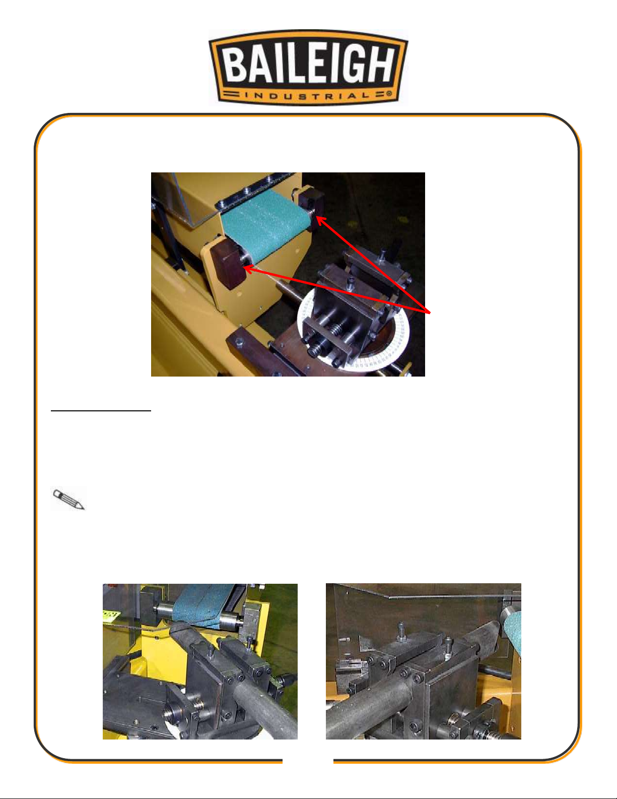
5. Find the desired mandrel and reinstall it the
same way, making sure the bearings are
fully seated in their respective saddles (B).
Note: It may be necessary to
clean any grinding debris from the saddles to
ensure an unobstructed fit for the bearings.
6. Retighten the belt tension hand wheel until the belt tension spring (C) is compressed to 1.25”
(31.75mm). This is the proper tension for all belts.
7. Plug the machine in and start momentarily to check the tracking of the belt.
a. The belt should track right down the center of the mandrel. If the tracking is off, the
tracking screw (D) is located slightly behind and below the motor.
b. Adjust by loosening the lock nut and turning the adjuster until the correct tracking is
achieved. Care should be taken when tracking so the belt does not track off the
mandrel. Always know where the off switch is.
15
15
B
8. The stock 36 grit belts that the machine comes with works best for most notching application,
although other grits are available.
Material Insertion
1. Once the proper mandrel and belt are installed, the material to be notched can be inserted
into the vise.
2. Open the vise an insert the material so that the end toward the mandrel extends past the
vise jaw approximately 2-3” (51-76mm) re-tighten the vise.
Note: Angled notches may require more material extending from the vise.
3. If an angle notch is required, loosen vise assembly by opening the locking lever and rotate
and position the vise assembly to the desired angle and retighten the lock lever, not to
exceed 60 degrees.

16
16
E
4. Position the material so the notch will end up being centered on the belt.
5. The depth of the notch is limited by the stop screw; this can be adjusted as needed, always
check for interferences before actually notching.
Off-center notches can be
accomplished by raising the “V” jaw of
the vise to the desired offset.
6. To raise the “V” Jaws, loosen the
(4) bolts, (2) on either side of each
jaw.
7. Turn the top jack screws (E) until
the desired offset is reached on
each of the jaw assembly’s.
8. Retighten the lock bolts.
Notching
1. With the motor running and the material clamped tightly in the vise, grab the main feed lever
and slowly pull the material into the spinning grinding belt.
2. Continue to feed until the desired notch depth is achieved. Don’t feed too fast, this will cause
the belt to wear prematurely and may push the belt off the mandrel. Thinner wall material
can be notched faster than thick wall.
3. After the desired notch depth is reached, activate the stop switch.
4. Make sure the spindle has stopped completely before removing and installing material.

17
17
PIPE
SIZES
O.D.
Pipe Schedules and Wall Thickness
5
10
40
80
160
XX STRONG
1/8
0.405
0.400
0.050
0.068
0.095
1/4
0.540
0.500
0.070
0.088
0.119
3/8
0.675
0.500
0.070
0.091
0.126
1/2
0.840
0.700
0.080
0.109
0.147
0.188
0.294
3/4
1.050
0.700
0.080
0.113
0.154
0.219
0.308
1
1.315
0.700
0.110
0.133
0.179
0.250
0.358
1-1/4
1.660
0.700
0.110
0.140
0.191
0.250
0.382
1-1/2
1.900
0.700
0.110
0.145
0.200
0.281
0.400
2
2.375
0.700
0.110
0.154
0.218
0.344
0.436
2-1/2
2.875
0.800
0.120
0.203
0.276
0.375
0.552
CAUTION: It must be determined by the customer that materials being
processed through the machine are NOT potentially hazardous to operator or
personnel working nearby.
MATERIAL SELECTION
When selecting materials keep these instructions in mind:
Material must be clean and dry. (without oil)
Material should have a smooth surface so it processes easily.
Dimensional properties of material must be consistent and not exceed the machine capacity
values.
Chemical structure of material must be consistent.
Buy certificated steel from the same vendor when possible.
STANDARD PIPE SIZES AND SCHEDULES TABLE
All sizes are in inches

18
18
ELECTRICAL SCHEMATIC

19
19
WARNING: Make sure the electrical disconnect is OFF before working on
the machine.
Maintenance should be performed on a regular basis by qualified personnel.
Always follow proper safety precautions when working on or around any machinery.
LUBRICATION AND MAINTENANCE
Check daily for any unsafe conditions and fix immediately.
Check that all nuts and bolts are properly tightened.
On a weekly basis clean the machine and the area around it.
Lubricate threaded components and sliding devices.
Apply rust inhibitive lubricant to all non-painted surfaces.
Remove the grinding debris as often as practical with a vacuum or light air blast.
Check bearings periodically for smooth operation, a rough rolling bearing will wear out
quickly and should be replaced immediately
Keep slide surfaces clean from grinding debris
Be sure always to use good belts, old belts can break easily and will decrease the
performance of the machine and may be unsafe.
Periodically check the power cord for cuts or bare wire and replace if damaged.
Oil Disposal
Used oil products must be disposed of in a proper manner following your local regulations.
Storing Machine for Extended Period of Time
If the Vertical Milling Machine is to be inactive for a long period of time, prepare the machine as
follows:
Disconnect the electrical supply from the power panel.
Empty and clean the coolant reservoir.
Clean and grease the machine.
Cover the machine.
Note: Proper maintenance can increase the life expectancy of your machine.

20
20
PARTS DIAGRAM
Main Tube Assembly

21
21
Slide Assembly

22
22
Vise Assembly

23
23
Mandrel Holder Assembly

24
24
Guard Assembly

25
25
Motor Assembly
26
26
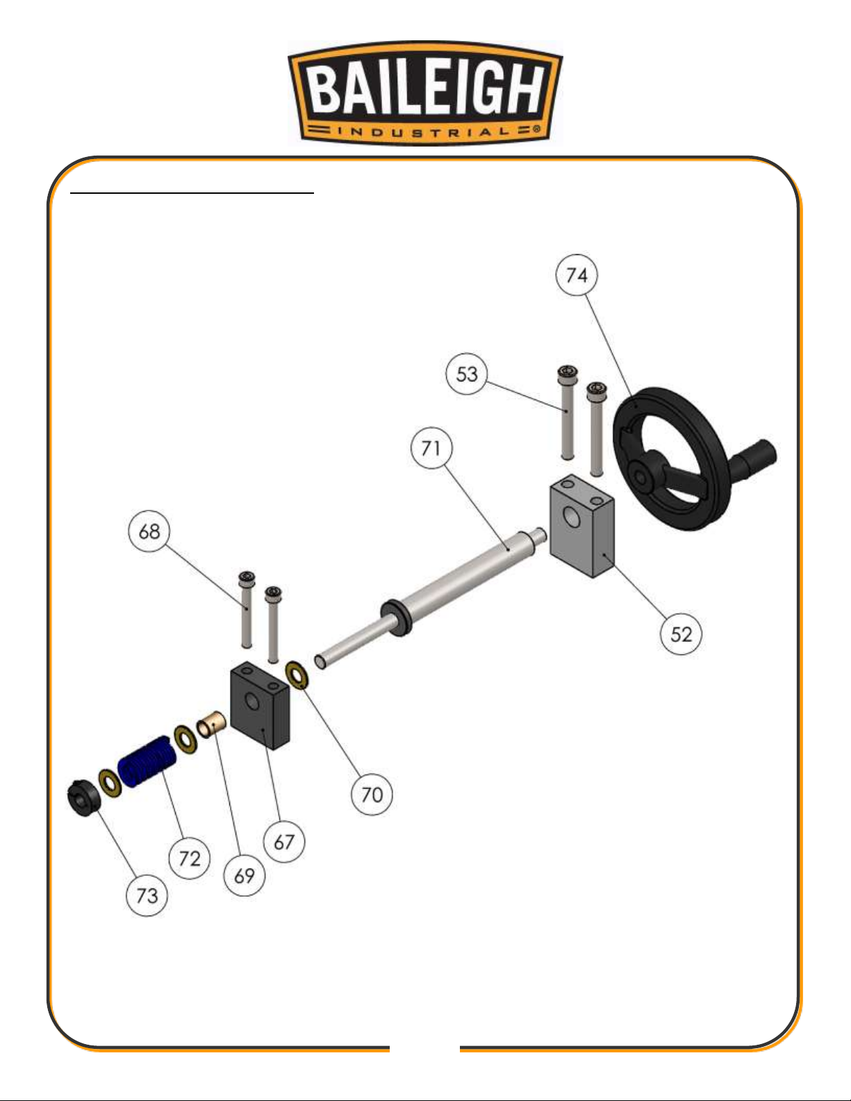
Tension Adjustment Assembly

27
27
Item
Part Number
Description
Qty.
1
M700-6A008
Side, Front
1 2 ME-M900-6A001
Main Frame Tube
1 3 M12 X 1.75 X 20
Hex Flange
6 5 ME-M900-6A029
Mtg. Block
1
6
M900-6A044
Shaft Support V2
1 7 M900-5A004
Angle Plate Assembly
1 8 ME-M900-7A009
Lever Pivot Pin
1 9 M10 X 1.5 X 20
Hex Flange
2
10
M10 X 1.5 X 25
Hex Flange
14
11
M10 X 1.5 X 35
Hex Flange
2
12
ME-M900-6A006
Slide Track
1
13
ME-M900-7A002
Slide Shaft
1
14
ME-M700-6A003
Roller Mtg. Plate (4")
1
15
M10 X 1.5 X 65
Hex Flange
3
16
M900-6A022
Plastic Slide
1
17
ME-M700-6A005
Slide Plate
1
18
M900-6A013
Plastic Slide Cap
1
19
ME-M900-6A046
Tube Clamp
2
20
M900-7A001
Bearing Tube
1
21
M8 X 1.25 X 30
SHCS
5
22
M10 X 1.5 X 65
SHCS
2
23
M10 X 1.5 X 20
SHCS
8
24
ME-M900-6A038
Bearing Block (Left)
1
25
ME-M900-6A039
Bearing Block (Right)
1
26
M10 X 1.5 X 25
SHCS
16
27
M900-6A034
Guard Spacer Block
2
28
ME-M900-6A030
Guard Mtg. Bar
2
29
M10 X 1.5 X 40
Hex Flange
4
30
PP-0322
0.75 ID X 1.25 OD X .125 THK
1
31
ME-M900-6A021
Drive Lever
1
32
PP-0659
0.75 ID X 0.875 OD X 0.5 LG
1
33
PP-0090
3/4" Split Collar
3
34
M900-5A005
Degree Disc
1
Parts List

28
28
Item
Part Number
Description
Qty.
35
ME-M900-6A042
Vise Lock Nut
1
36
M900-6A040
Lock Lever
1
37
M900-6A041
Lock Cap
1
38
M700-6A007
Switch Mount
1
39
M8 X 1.25 X 14
Hex Flange
2
40
PP-1298
On/Off Switch
1
41
Imperial
Star Washer
2
42
Imperial
M4 X 0.7 X 10 Cross Machine Screw
2
43
ME-M900-6A070
Slide Mount
1
44
M10 X 1.5 X 25
FHCSs
9
45
ME-M900-6A071
Slide Plate
1
46
ME-M900-7A013
Threaded Pivot Stud
1
47
M900-6A072
Fixed Slide Gib
2
48
M900-6A073
Gib Support
1
49
ME-M900-6A074
Adjustable Slide Gib
2
50
M8 X 1.25 X 25
SHCS
8
51
M6 X 1.0 X 25
SHCS
8
52
M900-6A018
Motor Adjusting Block
1
53
M10 X 1.5 X 80
SHCS
2
54
Imperial
M8 X 1.25 Hex Nut
2
55
PP-0143
1.25 OD X 1.0 ID X 1.25 LG
2
56
PP-0544
Seal
2
57
PP-1407
Spiral Retaining Ring
2
58
PP-0268
1/2" Female Rod End
1
59
PP-0107
1/2" Male Rod End
1
60
Imperial
1/2-20 Jam Nut
1
61
M12 X 1.75 X 25
Hex Flange
2
62
PP-0483
Spring Washer
1
63
PP-0388
1"-14 UNF Clamp Collar
1
64
Imperial
1/2-13 X 2 Threaded Rod
1
65
PP-0481
Spring Washer
1
66
Imperial
1/2-13 Hex Nut
2
67
ME-M900-6A019
Thrust Block
1
68
M8 X 1.25 X 65
SHCS
2
69
PP-0051
0.5 ID X 0.625 OD X 0.75 LG
1

29
29
Item
Part Number
Description
Qty.
70
PP-0055
0.5 ID X 1.0 OD X .0625 THK
3
71
M900-7A006
Adjustment Shaft
1
72
PP-0501
Spring
1
73
PP-0037
1/2" Clamp Collar
1
74
PP-0170
5.0 Handwheel
1
75
M900-6A032
Screw Block
1
76
M6 X 1.0 X 20
SHCS
2
77
PP-0532
Threaded Hand Nut
1
78
PP-0533
Knurled Locknut
1
79
ME-M700-7A001
Guard Spacer
2
80
PP-1077
3Hp (2.25kw) 1 Phase Motor
1
81
ME-M700-6A012
Motor Plate (Yen Motors)
1
82
ME-M700-7A016
Drive Pulley
1
83
BM-1750T-4
1.75 BRG Mandrel 4.0
1
84
PP-0558
Bearing
2
85
PP-0517
4.0" Belt
1
86
M700-6A004
Belt Guard
1
87
M6 X 1.0 X 14
SHCS
12
88
M700-6A006
Guard Cover
1
90
M700-6A010
Exhaust Chute Main Body
1
91
M8 X 1.25 X 25
Hex Flange
2
92
Imperial
M8 X 1.25 Hex Flange Nut
2
93
Imperial
3/8-16 X 3.25 Threaded Rod
1
94
Imperial
3/8-16 Hex Nut
1
95
PP-1533
Knob
2
96
M8 X 1.25 X 10
Set Screw
2
97
ME-M900-6A047
Vise Base
1
98
ME-M900-6A052
Pointer Disc
1
99
M900-7A011
Vise Lock Stud
1
100
ME-M900-6A048
Vise Shaft Support
2
101
FF-838-1
Flanged Sleeve Bushing
2
102
M6 X 1.0 X 16
FHCS
4
103
M900-7A014
Vise Slide Shaft
2
104
Imperial
1/8 X 1 Slotted Spring Pin
2
105
ME-M900-6A049
Vise Slide Block (R.H.)
1

30
30
Item
Part Number
Description
Qty.
106
ME-M900-6A055
Vise Slide Block (L.H.)
1
107
M900-7A012
Double Vise Screw
1
108
M900-6A050
Vise Jaw
4
109
ME-M900-6A051
Vise Cross Bar
2
110
Imperial
M6 X 1.0 Hex Nut
2

31
31
NOTES

32
32
NOTES

33
33
NOTES

34
34
BAILEIGH INDUSTRIAL, INC. 1625 DUFEK DRIVE MANITOWOC, WI 54220
PHONE: 920. 684. 4990 FAX: 920. 684. 3944
www.baileigh.com
BAILEIGH INDUSTRIAL, INC. 1455 S. CAMPUS AVENUE ONTARIO, CA 91761
PHONE: 920. 684. 4990 FAX: 920. 684. 3944
BAILEIGH INDUSTRIAL LTD. UNIT D SWIFT POINT
SWIFT VALLEY INDUSTRIAL ESTATE, RUGBY
WEST MIDLANDS, CV21 1QH UNITED KINGDOM
PHONE: +44 (0)24 7661 9267 FAX: +44 (0)24 7661 9276
WWW.BAILEIGHINDUSTRIAL.CO.UK
BAILEIGH INDUSTRIAL GMBH HOFENER STRAßE 64
70736 FELLBACH
DEUTCHSLAND
WWW.BAILEIGHINDUSTRIAL.DE
BAILEIGH INDUSTRIAL PTY. LTD.
P.O BOX 1573, 126 MELROSE DRIVE TULLAMARINE,
VIC 3043 AUSTRALIA
WWW.BAILEIGHINDUSTRIAL.COM.AU
 Loading...