


© 2021 Baileigh Industrial Holdings LLC
REPRODUCTION OF THIS MANUAL IN ANY FORM WITHOUT WRITTEN APPROVAL OF BAILEIGH INDUSTRIAL
negligence, or other occurrence.
Baileigh Industrial Holdings LLC
OPERATOR’S MANUA L
VARIABLE SPEED VERTICAL BAND SAW
MODEL: BSV-24VS-V2
HOLDINGS LLC IS PROHIBITED. Baileigh Industrial Holdings LLC, Inc. does not assume and hereby disclaims any
liability for any damage or loss caused by an omission or error in this Operator’s Manual, resulting from accident,
Manitowoc, WI 54221-0531
Baileigh-Sales@jpwindustries.com
P.O. Box 531
Phone: 920.684.4990
Fax: 920.684.3944
Rev. 03/2022

Table of Contents
THANK YOU & WARRANTY .......................................................................................... 1
INTRODUCTION ............................................................................................................. 3
GENERAL NOTES .......................................................................................................... 3
SAFETY INSTRUCTIONS .............................................................................................. 4
SAFETY PRECAUTIONS ............................................................................................... 6
Dear Valued Customer: ................................................................................................... 6
TECHNICAL SPECIFICATIONS ..................................................................................... 8
TECHNICAL SUPPORT ................................................................................................. 9
UNPACKING AND CHECKING CONTE NTS ................................................................ 10
TRANSPORTING AND LIFTING .................................................................................. 11
INSTALLATION ............................................................................................................. 11
Anchoring the Machine .............................................................................................. 12
GETTING TO KNOW YOUR MACHINE ....................................................................... 13
Control Panel ............................................................................................................. 15
Fence Guide .............................................................................................................. 18
ASSEMBLY AND SET UP ............................................................................................ 18
ELECTRICAL ................................................................................................................ 19
BEFORE EACH USE .................................................................................................... 21
Whenever Saw is Running ........................................................................................ 21
Blade Terminology ..................................................................................................... 22
Breaking in a Band Saw Blade .................................................................................. 22
Metal Chip Indicators ................................................................................................. 23
BLADE CARE ............................................................................................................... 23
Choosing A Saw Blade .............................................................................................. 23
Width of Blade ........................................................................................................... 24
Length of Blade ......................................................................................................... 24
BLADE BREAKAGE ...................................................................................................... 24
MATERIAL SELECTION ............................................................................................... 25
SAW OPERATION ........................................................................................................ 26
OPERATION OF BLADE WELDER .............................................................................. 27
Overall Description .................................................................................................... 27
Preparing the Saw Band Prior to Welding ................................................................. 28
Preparing the Blade Welder....................................................................................... 29
Making the Weld ........................................................................................................ 29
Annealing the Weld ................................................................................................... 31
Grinding the Weld ...................................................................................................... 31
SAW ADJUSTMENTS .................................................................................................. 32
Guide Post ................................................................................................................. 32
Graduated Scales to Show Tilt of Table .................................................................... 32
Adjusting the Blade Guides ....................................................................................... 33
Blade Tension Adjustment Wheel .............................................................................. 34
Changing a Blade ...................................................................................................... 35
BLADE TRACKING ....................................................................................................... 36

Regular Adjustment ................................................................................................... 36
LUBRICATION AND MAINTENANCE .......................................................................... 38
Blade Shear Lubricatio n ............................................................................................ 39
Upper Wheel Housing Items ...................................................................................... 39
Table Support Lubrication ......................................................................................... 39
CABINET ASSEMBLY – BREAKDOWN ....................................................................... 40
Cabinet Assembly – Part List..................................................................................... 41
WORK TABLE ASSEMBLY – BREAKDOWN ............................................................... 42
Work Table Assembly – Part List ............................................................................... 43
LOWER WHEEL SET ASSEMBLY – BREAKDOWN .................................................... 44
Lower Wheel Set Assembly – Part List ...................................................................... 45
GUIDEPOST ASSEMBLY – BREAKDOWN ................................................................. 46
Guidepost Assembly – Part List................................................................................. 47
UPPER WHEEL SET ASSEMBLY – BREAKDOWN .................................................... 48
Upper Wheel Set Assembly – Part List ...................................................................... 49
WELDER ASSEMBLY- BREAKDOWN ......................................................................... 50
Welder Assembly – Part List ..................................................................................... 51
ELECTRICAL DIAGRAM .............................................................................................. 53
Electrical Diagram Part List ....................................................................................... 54

1
1
THANK YOU & WARRANTY
Thank you for your purchase of a machine from Baileigh Industrial Holdings LLC. We hope that
you find it productive and useful to you for a long time to come.
Inspection & Acceptance. Buyer shall inspect all Goods within ten (10) days after receipt thereof. Buyer’s
payment shall co nstitute fin al accepta nce of t he Goo ds and shall ac t as a w aiver of the Buyer’s r ights to inspect or
reject the goods unless otherwise agreed. If Buyer rejects any merchand ise, Buyer must first obtain a Returned
Goods Authorization (“ RGA ”) number bef ore retur ning any go ods to S eller. Go ods retur ned witho ut an RGA w ill be
refused. Seller will not be responsible for any freight costs, damages to goods, or any other costs or liabilities
pertaining to goods ret urne d withou t a RG A. Sel ler sh all have the r ight to su bstit ute a co nformin g tender . B uyer wil l
be responsible for all freight costs to and from Buyer and repackaging costs, if any, if Buyer refuses to accept
shipment. If Goods are returned in unsalable condition, Buyer shall be responsible for full value of the Goods.
Buyer may not retur n any special-order G oods. Any Goods ret urned her eunder s hall be s ubject to a restoc king fee
equal to 30% of the invoice price.
Specifications. Seller may, at its o ption, mak e cha nges in the d esigns , spec ifica tions or com ponents of t he G oods
to improve the safety of su ch Goods, or if in Seller’s judgment, suc h chang es will be benef icial to the ir operatio n or
use. Buyer may not m ake any c hanges in t he s pecif icatio ns f or th e Goods un less Sell er appr oves of s uch c hanges
in writing, in which event Seller may impose additional charges to implement such changes.
Limited Warranty. Seller warrants to the original end-user that the Goods manufactured or provided by Seller
under this Agreement sh all be free of defects in mate rial or workmanship for a per iod of twelve (12) months from
the date of purchase, provided that the Goods are installed, used, and maintained in accordance with any
instruction manual or technical guidelines provided by the Seller or supplied with the Goods, if applicable. The
original end-user mus t give written not ice to Seller of any suspected defect in the Goods prior to the expiration of
the warranty period. The original end-user must also obtain a RGA from Seller prior to returning any Goods to
Seller for warranty ser vice under th is para graph . Selle r will not accept a ny res pons ibility for G oods r eturne d without
a RGA. The original end-us er shall be responsible for all costs and expenses associated with returni ng the Goods
to Seller for warranty s ervice. In th e event of a defect, Sel ler, at its sol e option, s hall repa ir or replace t he defectiv e
Goods or refund to the original end-user the purchase price f or such defective Goods . Goods are not eligible f or
replacement or return after a period of 10 days from date of receipt. The foregoing warranty is Seller’s sole
obligation, and the or iginal end-user’s exclusive rem edy, with r egard to any defective Goo ds. This lim ited warranty
does not apply to: ( a) die s ets, to oling, and saw b lades ; (b) per iod ic or ro utine maint enanc e and setup , (c) r epair or
replacement of the Go ods due t o norm al wear and t ear, (d) defects or d amage t o the Go ods res ulting fr om misuse,
abuse, neglect, or accidents, (f) defects or damage to the Goods resulting from improper or unauthorized
alterations, modifications, or changes; and (f) any Goods that has not been installed and/or maintained in
accordance with the instruction manual or technical guidelines pr ovid ed by Se ller .
EXCLUSION OF OTHER WARRA NTIES. THE FOR EGOING LIMITED WARRANTY IS IN LIEU OF ALL O THER
WARRANTIES, EXPRESS OR IMPLIED. ANY AND ALL OTHER EXPRESS, STATUTORY OR IMPLIED
WARRANTIES, I NCLUDING BUT NOT LIMITED TO, ANY WARRANTY OF MERCHANTABILITY OR FITNESS
FOR ANY PARTICULAR PURPOSE ARE EXPRESSLY DISCLAIMED. NO WARRANTY IS MADE WHICH
EXTENDS BEYOND THAT WHICH IS EXPRESSLY CONTAINED HEREIN.
Limitation of Liability. IN NO EVEN T SHALL SELLER B E LIABLE TO BUYER OR ANY OTHER PART Y FOR
ANY INCIDENTIAL, CONSEQUENTIAL OR SPECIAL DAMAGES (INCLUDING, WITHOUT LIMITATION, LOST
PROFITS OR DOWN TIME) ARISING FROM OR IN MANNER CONNECTED WITH THE GOODS, ANY BREACH
BY SELLER OR ITS AGENTS OF THIS AGREEMENT, OR ANY OTHER CAUSE WHATSOEVER, WHETHER
BASED ON CONTR ACT, TORT O R ANY OTHER TH EORY OF LIAB ILITY. BUYER ’S REMEDY WIT H RESPECT
TO ANY CLAIM ARISING UNDER THIS AGREEMENT IS STRICTLY LIMITED TO NO MORE THAN THE
AMOUNT PAID BY THE BUYER FOR THE GOODS.

2
2
Force Majeure. Seller shal l not be responsib le for any delay in the delivery of, or failure to deliver, Goods due t o
causes beyond Seller’s reasonable control inclu ding, with out lim itat ion, ac ts of God, acts of war or terror ism, enemy
actions, hostilities, strikes, labor difficulties, embargoes, non-delivery or late delivery of materials, parts and
equipment or transportation delays not caused by the fault of Seller, delays caused by civil authorities,
governmental regulations o r orders , fir e, lighte ni ng, nat ur al disas ters or any other cause beyond Seller’s reasonable
control. In the event of any such delay, performance will be postponed by such length of time as may be reasonably
necessary to compensate for the delay.
Installation. If Buyer purchases any Goods that require installation, Buyer shall, at its expense, make all
arrangements and connections necessary to install and operate the Goods. Buyer shall install the Goods in
accordance with any Se ller instructions and shall ind emnify Seller against any and a ll damages, demands, suits,
causes of action, claims an d expenses (including ac tual attorneys’ fees and c osts) arising directly or indirectly out
of Buyer’s failure to properly install the Goods.
Work By Others; Safety Devices. Un less agreed to in wri ting by Seller, Seller has no responsibility f or labor or
work performed by Buyer or other s, of any nature, relating to desig n, manufacture, fabrication , use, installation or
provision of Goods . Buyer is sole ly respons ible for furnishi ng and requirin g its employees and customers t o use a ll
safety devices, guards and safe operating procedures required by law and/or as set forth in manuals and instruction
sheets furnished by Seller. Buyer is responsible for cons ulting all operator manuals, ANSI or comparable safety
standards, OSHA regulations and other sources of safety standards and regulations applicable to the use and
operation of the Goods.
Remedies. Each of the rights and rem edies of Seller under this Agreement is c umulative and in addition to any
other or further remedies provided under this Agreement or at law or equity.
Attorney’s Fees. In the event legal action is necessary to recover monies due from Buyer or to enforce any
provision of this Agreement, Buyer shall be liable to Seller for all costs and expenses associated therewith,
including Seller’s actual attorney fees and costs.
Governing Law/Venue. This Agreement shall be construed and governed under the laws of the State of
Wisconsin, without applic ation o f conf lict of law pr inci ples. Eac h p arty agr ees that all acti ons or proce edings ar ising
out of or in connection with this Agreement shall be commenced, tried, and litigated only in the state courts sitting in
Manitowoc County, Wisconsin or the U.S. Federal C ourt for the Eastern Distr ict of Wisconsin. Each par ty waives
any right it may h ave to asser t the doctrine of “forum non conv eniens” or to object to venu e to the exten t that any
proceeding is brought in accordance with this section. Each party consents to and waives any objection to the
exercise of personal jurisdiction over it by courts described in this section. Each par ty waives to the fullest extent
permitted by applicable law the right to a trial by jury.
Summary of Return Policy.
• 10 Day accep tance period from date of delivery. Damage claims and order discrepancies w ill not be accepted
after this time.
• You must obtain a Baileigh issued RGA number PRIOR to returning any materials.
• Returned materials must be received at Baileigh in new condition and in original packaging.
• Altered items are not eligible for return.
• Buyer is responsible for all shipping charges.
• A 30% re-stocking fee applies to all returns.
Baileigh Industrial Hold ings LLC makes every effort to ensure that our posted specifications, ima ges, pricing and
product availability are as correct and timely as possible. We apologize for any discrepancies that may occur.
Baileigh Industrial Holdings LLC reserves the right to make any and all changes deemed necessary in the course of
business including but not limited to pricing, product specifications, quantities, and product availability.
For Customer Service & Technical Support:
Please contact one of our knowledgeable Sales and Service team members at:
(920) 684-4990 or e-mail us at Baileigh-Service@jpwindustries.com

3
3
INTRODUCTION
The quality and reliability of the components assembled on a Baileigh Industrial Holdings LLC
machine guarantee near perfect functioning, free from problems, even under the most
demanding working conditions. However, if a situation arises, refer to the manual first. If a
solution cannot be found, contact the distributor where you purchased our product. Make sure
you have the serial number and production year of the machine (stamped on the nameplate).
For replacement parts refer to the assembly numbers on the parts list drawings.
Our technical staff will do their best to help you get your machine back in working order.
In this manual you will find: (when applicable)
• Safety procedures
• Correct installation guidelines
• Description of the functional parts of the machine
• Capacity charts
• Setup and start-up instructions
• Machine operation
• Scheduled maintenance
• Parts lists
GENERAL NO TE S
After receiving your equipment remove the protective container. Do a complete visual
inspection, and if damage is noted, photograph it for insurance claims and contact your
carrier at once, requesting inspection. Also contact Baileigh Industrial Holdings LLC and inform
them of the unexpected occurrence. Temporarily suspend installation.
Take necessary precautions while loading / unloading or moving the machine to avoid any
injuries.
Your machine is designed and man uf actured to work smoothly and effic i entl y. Following proper
maintenance instructions will help ensure this. Try and use original spare parts, whenever
possible, and most importantly; DO NOT overload the machine or make any modifications.
Note: This symbol refers to useful information throughout the manual.
4
4
IMPORTANT
PLEASE READ THIS OPERATORS MANUAL CAREFULLY
It contains important safety information, instructions, and necessary operating procedures.
The continual observance of these procedures will help increase your production and
extend the life of the equipment.
SAFETY INS TRUCTIONS
LEARN TO RECOGNIZE SAFETY INF ORMATION
This is the safety alert symbol. When you see this symbol
on your machine or in this manual, BE ALERT TO THE
POTENTIAL FOR PERSONAL INJURY!
Follow recommended precautions and safe operating practices.
UNDERSTAND SIGNAL WORDS
A signal word – DANGER, WARNING, or CAUTION – is used with the safety alert symbol.
NOTICE, which is not related to personal injury, is used without a symbol.
DANGER: Indicates a hazardous situation which, if not
avoided, will result in death or serious injury.
WARNING: Indicates a hazardous situation which, if not
avoided, could result in death or serious injury.
CAUTION: Indicates a hazardous situation which, if not
avoided, could result in minor or moderate injury.
NOTICE: Indicates a situation which, if not avoided, could
result in property damage.
DANGER
WARNING
CAUTION
NOTICE

5
5
SAVE THESE INSTRUCTIONS.
Refer to them often and use them to instruct others.
PROTECT EYES
Wear safety glasses or suitable eye protection
when working on or around machinery.
PROTECT AGAINST NOISE
Prolonged exposure to loud noise can cause impairment or loss of
hearing. Wear suitable hearing protective devices such as earmuffs or
earplugs to protect against objectionable or uncomfortable loud noises.
DUST HAZARD
Wear appropriate dust mask. Dust created while using machinery can
cause cancer, birth defects, and long-term respiratory damage. Be aware
of the dust hazards associated with all types of materials.
CALIFORNIA PROPOSITION 65
WARNING: Cancer and Reproductive Harm.
www.P65Warnings.ca.gov
BEWARE OF CUT AND PINCH POINTS
Moving saw blade may result in loss of fingers or limb. DO
NOT operate with guard removed. Follow lockout/tagout
procedures before servicing.
EMERGENCY STOP BUTTON
In the event of incorrect operation or dangerous conditions, the machine
can be stopped immediately by pressing the E-STOP button. Twist the
emergency stop button clockwise (cw) to reset. Note: Resetting the EStop will not start the machine.

6
6
SAFETY PRECAUTIONS
Metal working can be dangerous if safe and proper operating procedures are not followed. As
with all machinery, there are certain hazards involved with the operation of the product. Using
the machine with respect and caution will considerably lessen the possibility of personal injury.
However, if normal safety precautions are overlooked or ignored, personal injury to the operator
may result.
Safety equipment such as guards, hold-downs, safety glasses, dust masks and hear i ng
protection can reduce your potential for injury. But even the best guard will not make up for poor
judgment, carelessness or inattention. Always use common sense and exercise caution in
the workshop. If a procedure feels da ngerous, don’t try it.
REMEMBER: Your personal safety is your responsibility.
WARNING: FAILURE TO FOLLOW THESE RULES MAY RESULT IN
SERIOUS PERSONAL INJURY
Dear Valued Customer:
• All Baileigh machines s hould be used only for their intended use.
• Baileigh does not recommend or endorse making any modifications or alterations to a
Baileigh machine. Modifications or alterations to a machine may pose a substantial risk of
injury to the operator or others and may do substantial damage to the machine.
• Any modifications or alt er ati ons to a Bail ei gh machine will invalidate the mac hi ne’s warranty.
PLEASE ENJOY YOUR BAILEIGH MACHINE! ....PLEASE ENJOY IT SAFELY!
1. FOR YOUR OWN SAFETY, READ INSTRUCTION MANUAL BEFO RE OPERATING THE
MACHINE. Learn the machine’s application and limitations as well as the specific hazards.
2. Only trained and qualified personnel can operate this machine.
3. Make sure guards are in place and in proper working order before operating
machinery.
4. Remove any adju sti ng tools. Before operating the machi ne, make sure any adjusting tools
have been removed.
5. Keep work area clean. Cluttered areas invite injuries.
6. Overloading machine. By overloading the machine, you may cause injury from flying parts.
DO NOT exceed the specified machine capacities.
7. DO NOT bypass or defeat any safety interlock systems.
8. Dressing material edges. Always chamfer and deburr all sharp edges.

7
7
9. Do not force tool. Your machine will do a better and safer job if used as intended. DO NOT
use inappropriate attachments in an attempt to exceed the machine’s rated capacity.
10. Use the right tool for the job. DO NOT attempt to force a small tool or attachment to do the
work of a large industrial tool. DO NOT use a tool for a purpose for which it was not
intended.
11. Dress appropriately. DO NOT wear loose fitting clothing or jewelry as they can be caught in
moving machine parts. Protective clothing and steel toe shoes are recommended when
using machinery. Wear a restri c ti ve hai r covering to contain long hair.
12. Use eye protection. Always wear ISO approved protective eye wear when operating
machinery. Wear a full -face shield if you are producing metal filings. Eye wear shall be
impact resistant, protective safety glasses with side shields which comply with ANSI Z87.1
specification. Use of e ye wear which does not comply with ANSI Z87.1 specification could
result in severe injury from breakage of eye protection.
13. Do not overreach. Maintain proper footing an d bal ance at al l tim es. DO NOT reach ov er or
across a running machine.
14. Stay alert. Watch what you are doing and use common sense. DO NOT operate any tool or
machine when you are tired.
15. Check for damaged parts. Before using any tool or machine, carefully check any part that
appears damaged. Check for alignment and binding of moving parts that may affect proper
machine operation.
16. Observe work area conditions. DO NOT use machines or power tools in damp or wet
locations. Do not expose to rain. Keep work area well lighted. DO NOT use electri cal l y
powered tools in the presence of flammable gases or liquids.
17. Blade adjustments and maintenance. Always keep blades sharp and properly adjusted for
optimum performance.
18. Keep children away. Children must never be allowed in the work area. DO NOT let them
handle machines, tools, or extension cords.
19. Keep visitors a safe distance from the work area.
20. Store idle equipment. When not in use, tools must be stored in a dry location to inhibit rust.
Always lock up tools and keep them out of reach of children.
21. DO NOT operate machine if under the influence of alcohol or drugs. Read warning
labels on prescriptions. If there is any doubt, DO NOT oper ate the mac hine.
22. Turn off power before checking, cleaning, or replacing any part s.
23. Be sure all equipment is properly installed and grounded according to national, state, and
local codes.
24. Keep all cords dry, free from grease and oil, and protected from sparks and hot metal.
25. Inspect power and control cables periodically. Replace if damaged or bare wires are
exposed. Bare wiring can kill! DO NOT touch live electrical components or parts.

8
8
Model No.
BSV-24VS-V2
Electrical
Power Supply
230V, 3ph, 60Hz
Main Drive Motor
3HP (2.2kw), 230V, 9.8A, 6P, 3Ph, 60Hz
Grinder Motor
1/8HP/ 230V, 1ph
Welding Type / Transformer
Butt Welder / 4.2KVA
Weld Capacity (Width)
.118” – .625” (3 – 16mm)
Speed Meter
DM94C
Work Lamp
LED Lamp 220V 9W
Inverter
3HP/ 230V /3ph RM6 RHYMEBUS
Power Cord
14WAG X4C 2.08MM X4C 105℃/ 300VAC UL
Capacity
Blade Speed
Variable Speed
Cutting Capacity (Height)
12.2” (310mm)
Throat Depth
23.62" (600mm)
Blade Width (Min-Max.)
0.12" – 0.63" (3 – 16mm)
Blade Thickness
Blade Length (Min-Max.)
177.95" – 179.13" (4520 – 4550mm)
Standard Machine Blade (included)
Blade Speed
85 – 2200 FPM
Table Tilt
15° L & 45° R
Table Height
36.22" (920mm)
Table Area
24.4" x 24.4" (620 x 620mm)
Blade Wheel Dimension
24.4” (620mm)
Packing
Net Weight
935lbs (425kgs)
Gross Weight
1031lbs (469kgs)
Machine Overall Dimension (LxHxW)
451.18” x 77.95” x 33.07” (1300 x 1980 x 840mm)
Packaging Overall Dimension (LxHxW)
53.54” x 85.43” x 33.46” (1360 x 2170 x 850mm)
TECHNICAL SPECIFICATIONS
.025” (0.64mm)
0.511” (13mm) 14T

9
9
TECHNICAL SUPPORT
Our technical support department can be reached at 920.684.4990 and asking for the support
desk for purchased machines. Tech Support handles questions on machine setup, schematics,
warranty issues, and individual parts needs: (other than die sets and blades).
For specific application needs or future machine purchases contact the Sales Department at:
Baileigh-Service@jpwindustries.com, Phone: 920.684 . 49 90, or Fax: 920.684.3944.
Note: The photos and illus tr ati ons us ed in this manual are representative only and
may not depict the actual color, labeling or accessories and may be intended to illustrate
technique only.
Note: The specifications and dimensions presented here are subject to change
without prior notice due to improvements of our products.
10
10
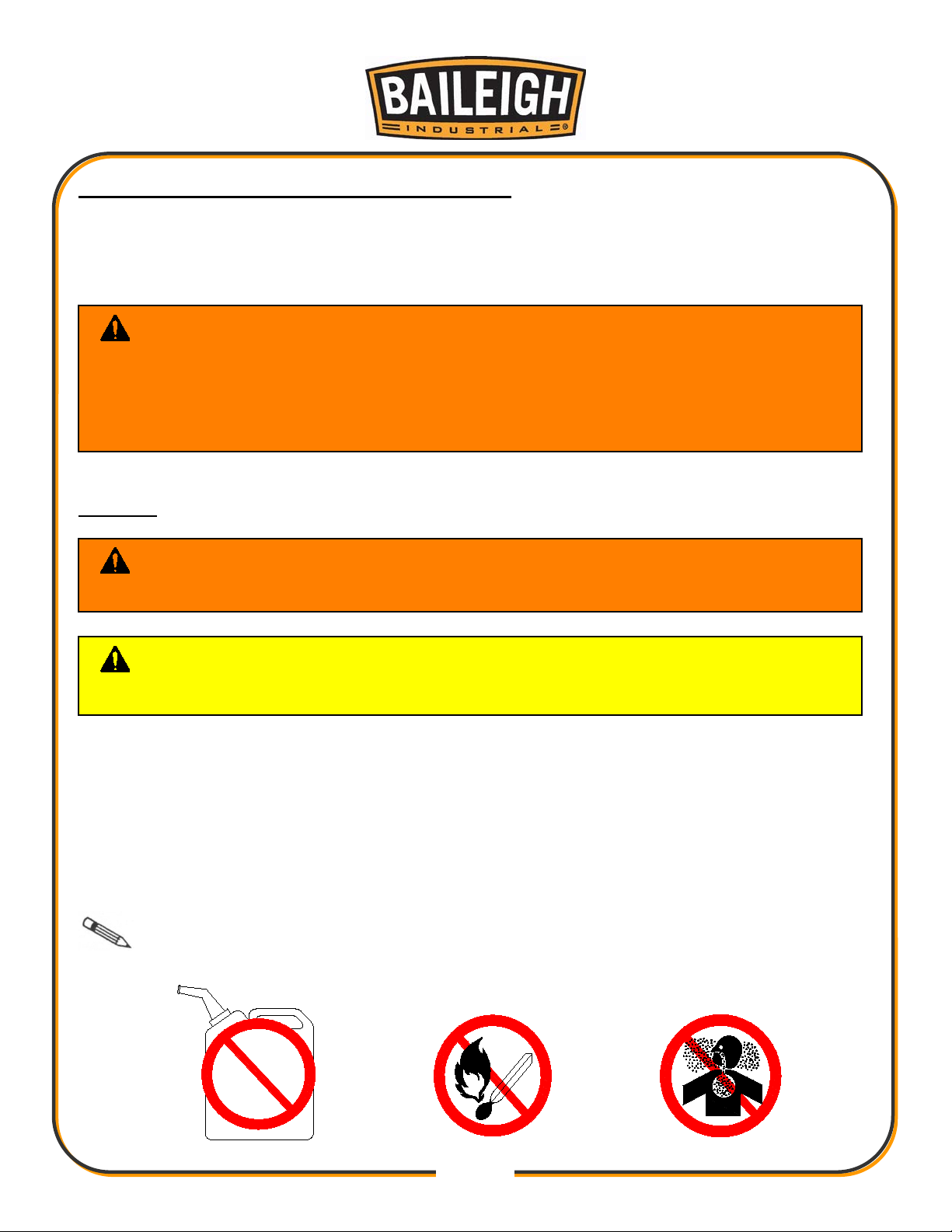
discard any plastic
the machine. They have low flash points and can explode or cause fire.
UNPACKING AND CHECKING CONTENTS
Your Baileigh machine is shipped complete . Separate all parts from the packin g mat er ial and
check each item carefully. Make certain all items are accounted for before discarding any
packing material.
WARNING: SUFFOCATION HAZARD! Immediately
bags and packing materials to elimina te choking and suffocation hazards to children
and animals.
If any parts are missing, DO NOT place the machine into service until the missing
parts are obtained and installed correctly.
Cleaning
WARNING: DO NOT USE gasoline or other petroleum products to clean
CAUTION: When using cleaning solvents work in a well-ventilated area.
Many cleaning solvents are toxic if inhaled.
Your machine may be shipped with a rust pr oof waxy coating and/or grease on the exposed
unpainted metal surfac es . Fully and completely remove this protective coating using a
degreaser or solvent cleaner. Moving items will need to be moved along their trav el path t o
allow for cleaning the entire surface. For a more thorough cleaning, some parts will occasionally
have to be removed. DO NOT USE acetone or brake clea ner as th ey may dama ge pai nted
surfaces.
Follow manufacturer’s label instructions when using any type of cleaning product. After cleaning,
wipe unpainted metal surfaces with a light coating of quality oil or grease for protection.
Important: This waxy coat ing is NOT a lubricant and will cause the machine to
stick and lose performance as the coating continues to dry.
GAS

11
11
NOTICE: Lifting and carrying operations should be carried out by skilled workers, such as a
chain carefully, making sure the machine is well balanced.
TRANSPORTING AND LIFTING
truck operator, crane operator, etc. If a crane is used to lift the machine, attach the lifting
Follow these guidelines when lifting with truck or trolley:
• The lift truck must be able to lift at least 1.5 – 2 times
the machines gross weight.
• Make sure the machine is balanced. While
transporting, avoid rough or jerky motion, and maintain
a safe clearance zone around the transport area.
• Use a forklift with sufficient lifting capacity and forks
that are long enough to reach the complete width of
the machine.
• Remove the securing bolts that attach the machine to
the pallet.
• Approaching the machine from the side, lift the machine on the frame taking care that there
are no cables or pipes in the area of the forks.
• Move the machine to the required position and lower gently to the floor.
• Level the machine so that all the supporting feet are taking the weight of the machine and no
rocking is taking place.
INSTALLATION
IMPORTANT:
Consider the following when looking for a suitable location to place the machine:
• Overall weight of the machine.
• Weight of material being processed.
• Sizes of material to be processed through the machine.
• Space needed for auxiliary stands, worktables, or other machinery.
• Clearance from walls and other obstacles.
• Maintain an adequate working area around the machine for safety.
• Have the work area well illuminated with proper lighting.
• Keep the floor free of oil and make sure it is not slippery.

12
12
.31"
(7.87mm)
.50"
(12.7mm)
• Remove scrap and waste materials regularly, and make sure the work area is free from
obstructing objects.
• If long lengths of material are to be fed into the machine, make sure that they will not extend
into any aisles.
• LEVELING: The machine should be sited on a level, concrete floor. Provisions for securing it
should be in position pri or to placin g the mac hi ne. T he acc ur acy of any mac hine depends on
the precise placement of it to the mounting surface.
• FLOOR: This machine distributes a large amount of weight over a small area. Make certain
that the floor is capable of supporting the weight of the machine, work stock, and the
operator. The floor should also be a level surface. If the unit wobbles or rocks once in place,
be sure to eliminate by using shims.
• WORKING CLEARANCES: Take into consideration the size of the material to be
processed. Make sure that you allow enough space for you to operate the machine freely.
• POWER SUPPLY PLACEMENT: The power supply should be located close enough to the
machine so that the power cord is not in an area where it would cause a tripping hazard. Be
sure to observe all electrical codes if installing new circuits and/or outlets.
Anchoring the Machine
• Once positioned, anch or the machi ne to the floor, as shown in
the diagram. Use bolts and expansion plugs or sunken tie rods
that connect through and are sized for the holes in the base of
the stand.
• This machine requires a solid floor such as concrete at a
minimum of 4” (102mm) thick. 6” (153mm) minimum is preferred.

13
13
GETTING TO KNOW YOUR MACHINE

14
14
Item
Description
Function
Verify machine power requirements before making
connections. Verify 11 0V or 220 V
Grinds welded area of blade back to ori gi nal mat er ial
thickness.
C
Blade Welding Station
Welds blade together.
D
Blade Shear
Trims end of blade square prior to welding
Removes power to the operating controls and stops
operation.
Push buttons to start and run the saw blade and stop the
saw blade when the cut is complete.
Changes the speed of the saw blade. Used while the
machine is running.
Displays the speed of the blade in MPM (Meters Per
Miniute).
J
Upper Access Door
Houses the upper pulley, and tensioner.
Guide Post Tension Knob
(not visible in this view)
Located on the back side of the upper whell housing,
use this to loosen the guide post fo adjustment.
Use to raise or lower the guide post to provide minimum
clearence to the work piece.
M
Work Lamp
Provide additional light to the cut area.
N
Blade Tension Adjustment
Turn to incease or decrease blade tension.
Sets a specific and repeatable distance for cutting
material to a specific width.
Provide air to the work site to blow chip away from cut
area.
Q
Upper Blade Guide
Holds the blade in position and minim izes blade twist.
Supports material and provide several ways to control
angle cuts.
Trunions used to allow the tabl e to tilt up to 15° left or
right.
T
Lower Blade Access Door
Houses the drive pulley.
Miter Gauge (not shown)
Sets a specific and repeatable angle for cutting material.
A Power Cord
B Grinder
E Emergency Stop Switch
F Start / Stop Control
G Variable Speed Hand Wheel
H Speed Display
K
L Guide Post Adjustment Knob
O Fence
P Air Tube
R Work Table
S Table Tilt

15
15
BG C
A
H F D
E
Control Panel
A DRO Indicator. Displays the speed of the
blade in FPM (Feet Per Minute).
B Speed Control. This potentiometer will vary
the input signal to the VFD which in turn will vary the
frequency output to the motor thus controlling the
speed of the motor and then the blade.
C Power Indicator Lamp. The power indicator
lamp will illuminate when the key switch is turned to
the ON position.
D Key Switch. The key switch powers the
operating controls On to allow either cutting or
welding.
E Function Selector Switch. This selector
switch provides for one opera ti on at a tim e. In t he Left
position, the welder will be active. In the Right
position, the saw will be active.
F On Push Button. Press this button to start and
run the blade when operating conditions are safe for
the blade to move. Make sure the blade is rotating
downward towards the work table .
G Stop Push Button. Press this button to stop
the blade any time that the operator is not directly and
actively engaged in a cutting operation.
H Emergency Stop Button (E-Stop). In the
event of incorrect operation or dangerous conditions,
the machine can be stopped immediately by pressing
the E-STOP button. Twist the emergency stop button
clockwise (cw) to reset. Note: Resetting the E-Stop
will not start the machine.

16
16
J
K
L
Blade Shear
The blade shear is attached to the saw frame, just left
and up from the saw band weld station.
It will cut saw bands ranging in width from 0.062” to 1”
(1.6mm to 25.4mm) and thickness of 0.025” to 0.035”
(0.63mm to 0.89mm).
Weld Station
J Welde r Control s. The Dial is used to set the
pressure or force used to press the ends of the blade
together.
Press and hold the Green push button to complete the
weld. Press and hold the Red push button to Anneal
the weld.
K Weld Jaws / Electrodes. The weld jaws clamp
and hold the blade in position during the weld. The left
jaw moves toward the right using the Pressure Dial.
Both jaws are the electrodes which transfer the
electrical current to the blad e materi al bei n g w elded t o
create the weld puddle (melted metal) which will flow
together to melt the end together as one piece.
L Grinder Switch. Toggle the switch to the ON
position to start and run the grinding wheel. Grind the
blade to remove rough spots and create a smooth
surface without making the area thinner than the rest
of the blade.

17
17
Upper
Lower
Lower Wheel Housing
The lower wheel housing has the lower wheel (drive
wheel), the debris brush, and the debris tray.
• The lower wheel is the drive wheel which is
connected via a shaft to the drive sheave and thus
the motor through the drive belt.
• The brush is used to help control / remove chips
and metal fillings from getting between the blade
and wheel. Keep it clean and adjust as it wears.
The bristles should have a slight pressure against
the pulley at all times.
• The debris tray will collect larger chips and metal
fillings. The tray will slide out and back in for
regular cleaning.
Tilting Work Table
The work table may be tilted from 15° to 45°. The
outboard side of the table will lift to create a 15° angle
or lowered to a 45° angle.
Tilting the table is done on the back side of the saw.
Just under and forward of the degree scale is the
clamping nut. Loosen the nut, tilt the table to the
desired angle and tighten the nut to hold the angle.
Upper and Lower Blade Guides
The blade guides provide side-to-side and back support for keeping the blade straight while
cutting material. The blade guides are tungsten steel where they come in contact with the blade
to reduce wear on the guides. The guides must be kept properly adjusted for accurate cuts.

18
18
Fence Guide
A fence guide is provided with this saw to ad in
precise cut lengths and repeat cuts.
ASSEMBLY AND SET UP
WARNING: For your own safety, DO NOT connect the machine to the
power source until the machine is completely assembled and you read and
understand the entire instruction manual.
Fence Installation
• Remove and retain the two hex head cap screws
installed into the front work table edge.
• Position the fence mounting bar onto the front
edge of the work table and install and tighten the
two hex head cap screws.
• Install the fence by setting the clamping body over
the fence rail with the clamping handle lifted.
• Slide the fence left or right as needed and press
down on the lock handle with just enough force to
hold the fence in position.

19
19
ELECTRICAL
WARNING: Baileigh Industrial Holdings LLC is not responsible for any
damage caused by wiring up to an alternative 3-phase power source other than direct
3-phase. If you are using an alternate power source, consult a certified electrician or
contact Baileigh Industrial Holdings LLC prior to energizing the machine.
CAUTION: HAVE ELECTRICAL UTILITIES CO NNECTED TO MACHINE BY
A CERTIFIED ELECTRICIAN!
Check if the available power supply is the same as listed on the machine nameplate.
WARNING: Make s ure the grounding wire (green) is properly connected
to avoid electric shock. DO NOT switch the position of the green grounding wire if
any electrical plug wires are switched during hookup.
Power Specifications
Your machine is wired for 230 volts, 60hz alternating current. Verify the input power supply
before making any electr i cal connec ti ons. Before connecting the machine to the power source,
make sure the power source is OFF.
Before switching on the power, you must check the voltage and frequency of the power to see if
they meet with the requireme nt, t he allow ed range for the voltage is ±5%, and for the frequency
is ±1%.
Considerations
• Observe local electrical codes when connecting the machine.
• The circuit should be protected with a time delay fuse or circuit breaker with an amperage
rating slightly higher than the full load current of machine.
• A separate electrical circuit should be used for your machines. Before connecting the motor
to the power line, make sure the switch is in the “OFF” position and be sure that the electric
current is of the same characteristics as indicated on the machine.
• All line connections should make good contact. Running on low voltage will damage the
motor.
• In the event of a malfunction or breakdown, grounding provides a path of least resistance for
electric current to reduce the risk of electric shock. This machine is equipped with an electric
cord having an equipment-grounding conductor and a grounding plug. The plug must be
plugged into a matching outlet that is properly installed and grounded in accordance with all
local codes and ordinances.

20
20
WARNING: In all cases, make certain the receptacle in question is
properly grounded. If you are not sure, have a qualified electrician check the
receptacle.
• Improper connection of the equipment-grounding conductor can result in risk of electric
shock. The conductor with insulation having an outer surface that is green with or without
yellow stripes is the equipment-grounding conductor. If repair or replacement of the electric
cord or plug is necessary, do not connect the equipment-grounding conductor to a live
terminal.
• Check with qualified electrician or service personnel if the grounding instructions are not
completely understood, or if in doubt as to whether the machine is properly grounded.
• Repair or replace damaged or worn cord immediately.
Power cord connection:
1. Turn the main disconnect switch on the control panel to the OFF position.
2. Unwrap the power cord and route the cord away from the machine toward the power supply.
a. Route the power cord so that it will NOT become entangled in the machine in any
way.
b. Route the cord to the power supply in a way that does NOT create a trip hazard.
3. Connect the power cord to the power supply and check that the power cord has not been
damaged during installation.
4. When the machine is clear of any obstruction. The main power switch may be turn ON to test
the operation.
5. Turn the switch OFF when the machine is not in operation.

21
21
BEFORE EACH USE
• For dusty operations, wear a face shield along with safety goggles.
• It is important to choose the right blade for the material and the type of cutting you plan to
do. This saw is equipped with a bi-metallic blade which can be used to cut stainless steel,
steel, iron, brass, aluminum, wood, plastic.
• Make sure the direction of rotation arrow on the blade matches the direction arrow on the
saw. The blade teeth should always point downward at the front of the saw.
• Make sure the blade is sharp, undamaged and properly aligned. With the saw unplugged,
push the power-head all the way down. Rotate the blade by hand checking for clearance. If
the blade hits anything, make the adjustments shown in the Maintaining Maximum Cutting
Capacity section.
• Never cut freehand.
• Make sure the cut-off piece can move sideways after it is cut off. Otherwise, it could get
wedged against the blade and thrown violently.
• Never turn the saw "ON" before clearing everything except the work piece beneath the
blade.
• Never put lubricants on the blade while it is spinning.
Whenever Saw is Running
• Never confine the piece being cut out.
• Never hold it, clamp it, touch it, or use length stops against it. It must be free to move
sideways. If confined, it could get wedged against the blade and thrown violently.
• Avoid awkward hand positions where a sudden slip could cause a hand to move into the
blade.
• Let the blade reach full speed before cutting.
• Feed the saw into the work piece only fast enough to let the blade cut without bogging down
or binding.
• Before freeing jammed material, turn the switch off and unplug the saw. Wait for all moving
parts to stop.
• After finishing a cut, keep holding the saw bow down, release the switch, and wait for all
moving parts to stop before moving your hands.

22
22
The widest part of the blade measured from the back edge of the
blade to the tip of the tooth.
B
GULLET DEPTH
The distance from the tooth tip to the bottom of the curved area.
The angle of the tooth face from a line perpendicular to the length
of the blade.
The distance between the back edge of the blade and the bottom
of the gullet.
E
TOOTH PITCH
The distance between tooth tips.
The number of teeth per inch when measured from gullet to
gullet.
G
GAUGE
The thickness of the blade.
H
TOOTH SET
The distance a tooth is bent from the blade.
I
KERF
The width of material that is removed by the blade when cutting.
A
B
C
D
E
F
G
H
I
Blade Terminology
A BLADE WIDTH
C TOOTH RAKE
D BLAD E BAC K
F TPI
Breaking in a Band Saw Blade
Sharp cutting edges with extremely small edge radii are required for high cutting capacity. To
achieve the optimal tool life we recommend breaking-in the blade accordingly. The correct
cutting speed is determined by the material being cut and its dimensions. It is very important
that the new blade is first used with only 50% of the determined feed rate. This will avoid microbreakages of the blade because of too large chip thicknesses. New band saw blades may tend
toward vibrations and vibration sounds. In this case a slight reduction of the cutting speed is
helpful. With small workpiece dimensions approximately 300cm² of the material should be cut
for breaking-in. If large work piece dimensions are to be cut we recommend a breaking-in period
of about 15 minutes. After breaking-in you may slowly increase the feed rate up to the
determined value.

23
23
Metal Chip Indicators
Chips are the best indicator of correct material feed force. Monitor chip information and adjust
feed accordingly.
• Thin or Powdered Chips – increase feed rate or reduce saw speed
• Burned Chips – reduce feed rate and / or saw speed
• Curly Silvery and Warm Chips – optimum feed rate and saw speed
Baileigh Industrial offers a wide selection of tooth styles for various cutting applications. Please
phone Baileigh Industrial at (920.684.4990) or fax to (920.684.3944) to have one of our
technicians assist you in selecting the proper band saw blade for your cutting applications.
BLADE CARE
The bandsaw blade is subjected to a tremendous amount of strain. Make sure to always use the
appropriate feed rate for the type material you are cutting.
Be sure to select a blade of the proper width, style, and pitch that will produce the best cut in
your material. Choosing the wrong blade can produce excess heat that can adversely affect the
life of the blade.
A clean blade performs much better than one that is dirty. Blades that are gummed up and dirty
offer more resistance when cutting through the material. This in turn creates unnecessary heat
in the blade.
Choosing A Saw Blade
A general-purpose blade is furnished with this band saw.
To achieve a quality, economical, and efficient saw cut, the following points must be taken into
consideration:
• Type of material being cut (ferrous or non ferrous)
• Material hardness and phy si cal di me nsi ons
• Blade descent rate
• Longitudinal speed of blade
• Blade tooth profile

24
24
Choose a tooth pitch that is suitable for the workpiece. Thin walled profiles, including tubes and
pipes require close toothing. At least 3-6 teeth should be in contact with the material while
cutting. Large solid or transverse sections require widely spaced toothing to allow for greater
volume of chips and better tooth penetration. Soft materials such as plastics, light alloys, mild
bronze, Teflon, etc. require widely spaced toothing to avoid clogging.
Width of Blade
The blade width determines the largest and the smallest curve that can be cut. Usually the wider
a blade is, the more accurate and straighter it will cut.
Length of Blade
The length of the band saw blade can be measured with a tape measure at its circumference or
by the formula below:
Blade Length = (2 x A) + (3.14 x B)
A = the distance in inches between the band saw pulley centers (when the upper pulley is
midway in its adjustment range).
B = the band saw pulley diameter.
BLADE BREAKAGE
In some cases, blade breakage is unavoidable due to the stresses that are imparted on the
blade. Avoidable breakage is often the result of poor care, or poor operator judgment when it
comes to adjusting or mounting the blade or blade guides.
Listed below are some of the more common reasons for blade breakage.
• Top blade guide assembly is set too high above the piece part.
• The blade is tensioned incorrectly.
• Piece part is fed into the blade too quickly.
• Blade teeth are dull or broken.
• Blade is not properly aligned with the guides.
• Forcing a large width blade to cut a sm all radius.
• Using a blade with an improperly finished weld joint.
• Allowing the blade to run when not in use. (NEVER leave an unattended blade running.)

25
25
potentially hazardous to operator or
personnel working nearby.
MATERIAL SELECTION
CAUTION: It must be determined by the customer that materials being
processed through the machine are NOT
When selecting materials keep these instructions in mind:
• Material must be clean and dry. (without oil)
• Material should have a smooth surface, so it processes easily.
• Dimensional properties of material must be consistent and not exceed the machine capacity
values.
• Chemical structure of material must be consistent.
• Buy certificated steel from the same vendor when possible.

26
26
SAW OPERATION
CAUTION: Always wear proper eye protection operating the saw. The
bandsaw blade is sharp and will cut fingers and hands. Keep hands and fingers clear
of the blade. Use a block of wood as a pusher for the material being cut. It is
recommended to always wear leather gloves when working near the blade.
1. Verify the work area including the table is clear
of obstructions.
2. Set the guide post (A) to approximately .25”
(6.35mm) above the piece part and tighten the
guide post knob.
3. Set the table and if being used, the fence as
needed to complete the cut. Have a push block
within reach without crossing the blade path or
vision of the cut area. Simulating the cut without
power may be helpful.
4. Set the work lamp position to provide additional
light at the cut site without inter
material or the ability to maintain control of the
material for the entire cut.
5. Have proper support for the material to be cut.
This should include both the finished piece and
the excess material.
6. Press the start button to energize the motor
stating the blade. The saw blade should now be
moving. If any abnormal sounds or vibrations
are noticed, press the red stop button
immediately.
7. Adjust the variable speed (B) until the desired
speed is indicated on the speed display.
8. Carefully place the material on the table.
9. When positioned, feed the material into the blade using a steady smooth motion.
10. When the cut is complete, press the red stop button on the control panel and wait until the
blade stops before removing any material near the blade.
fering with the

27
27
CAUTION:
blade.
OPERATION OF BLADE WELDER
Overall Description
The bandsaw blade is sharp and can cut your hand or fingers.
Always disconnect power to the saw and wear leather gloves when working near the
The weld station on the Baileigh band saw can butt weld and anneal blades from 0.118” (3mm)
to 0.625” (16mm) wide by 0.032” (0.8mm) thick. It is a resistance type welder with two jaws that
secure the blade ends during the welding process. A selector knob is turned counterclockwise
(ccw) to pre-load the left jaw, forcing the blade ends against one another. When the operator
presses the weld button, electric current passes through the butted blade ends. The left jaw
blade end is pushed into the molten puddle and welded to the right blade end. Remove the
blade from the jaws if any weld flash is present and carefully grind it off. The blade joint must
now be placed back into the jaws where annealing of the weld joint takes place. This procedure
will reheat the weld area so it is not so brittle and should return it to its original condition.
It may become necessary to weld blades when:
• They break unexpectedly and the teeth are still sharp enough to cut.
• You need to make blades from a bulk saw blade coil.
• When you need to weld a blade that was cut to make an internal contour cut on a piece part.

28
28
CAUTION:
Grind
Here
Good Weld
Poor Weld
Weld centered
in gullet of blade
Consistent tooth
spacing
Weld not centered
in gullet of blade
Unremoved tooth
embedded in weld
Inconsistent
tooth spacing
Incomplete weld
Blow-out
hole
Preparing the Saw Band Prior to Welding
Blade Cutter To cut the band apart or to cut the band
to a specified length, use the blade shear. The shear is
capable of cutting saw bands from 0.118” to .625”
(3mm to 16mm) in width and 0.025” to 0.035” (0.63mm
to 0.89mm) in thickness. To use the blade cutter, raise
the handle, lay between the blades perpendicular to
the cutting knife, and make the cut.
If the saw band is not square after shearing, use the
grinding wheel to square it up. Take small cuts so as
not to overheat the blade band. To get both ends of
the band to match perfectly, twist it and hold the ends
so that the teeth are on opposite sides and pointing in
opposite directions. Now grind as shown below.
Tooth Spacing on Blade Band Occasionally one or
more teeth may have to be ground off on either side of
the cut to ensure blade tooth uniformity.
Shear Hazard – Keep Hands From Under Blade.

29
29
WARNING:
Preparing the Blade Welder
The electrical current that flows through the blade welder
when operating could cause Serious Personal Injury or Death.
To avoid the risk of electrocution, never touch any metal part of the weld station
during welding or annealing of the blade.
1. Make sure the jaws of the welder are clean to
make good electrical contact.
2. Check that the jaws will adequately hold the
thickness of blade you are usin g.
3. The left jaw should slide easily when turning the
weld force selector knob.
4. Check over the grinding wheel and make sure it is
in good condition.
Making the Weld
1. Before making a weld, turn off the band saw motor
by pressing the red “stop” button.
2. Turn the weld pressure selector knob clockwise
(cw) to the “0” position.
3. After squaring the ends of the blade, insert the
spine edge of the blade into each jaw butting the
cut ends together and centered between the jaws.
4. Secure the blade by raising the handles. Check that the blade ends fit together with no gap.
If a gap is noticed, remove and re-sq uar e th e blade.
5. Turn the weld force selector knob from “0” to the third marker. This would be for a 0.25”
(6.3mm wide blade. (Every 2mm of blade width = 1 marker approx.). this applies pressure to
hold the ends of the blade togeth er.

30
30
WARNING:
Good Weld
Poor Weld
Weld centered
in gullet of blade
Consistent tooth
spacing
Weld not centered
in gullet of blade
Unremoved tooth
embedded in weld
Inconsistent
tooth spacing
Incomplete weld
Blow-out
hole
2 3 4 5
Check blade band misalignment
with a straight edge
Sparks from the blade welding operation can be thrown in all
directions and can cause serious personal injury or fire. When using the blade
welder, always protect yourself and others from flying sparks. Keep fire extinguisher
equipment close by and DO NOT weld near flammables.
6. Press and hold the green weld button until the left jaw blade end is pushed into the molten
puddle and welded to the right blade end. As soon as the left jaw moves into the right jaw,
release the green weld button. Electric current passes through the butted blade ends. The
left jaw blade end is pushed into the molten puddle and welded to the right blade end.
Inspect the weld carefully after removing from the welder.
7. If you see what appears to be an excessive amount of flashing you can try backing off on the
weld force setting.

31
31
CAUTION:
CAUTION:
Bend Like This
Not Like This
Annealing the Weld
The bandsaw blade is sharp and can cut your hand or fingers.
Heat from the welding and annealing process can cause severe burns. Always wear
leather gloves when working near the blade.
1. When a saw band is butt welded, the site of the weld “air hardens” and will become brittle.
To return the metal to its approximate original state it must be gradually heated and cooled
several times called annealing.
2. Turn the weld force selector knob to “0”.
3. Clamp the saw band in the jaws making sure to carefully cent er th e wel d. It is still brittle.
4. Press the red annealing button quickly with a few short bursts to ma ke th e weld ar ea a dull
orangish-red. (The wider the blade, the more bursts and time it will take.) After reaching a
dull orangish-red, allow the area to cool 15-30 seconds and then repeat the heat twice more.
Too much heat can damage the temper or burn through and destroy the weld.
5. After welding and tempering the blade, test the strength and flexibility of the saw band by
bending it in an arc similar to the pulley on the saw.
Grinding the Weld
The bandsaw blade is sharp and can cut your hand or fingers.
Keep hands and fingers away from rotating grinding wheel. Wear proper eye
protection. Always wear leather gloves when working near the blade.
1. The grinding wheel is used for both preparing the saw band for welding and rem ov ing f lash
after annealing. Flash must be removed from both sides of the weld to maintain the blades
actual thickness. This w i ll then allow the bl ad e to pass t hr ou gh the gui des with out any
obstructions.
2. DO NOT burn or overheat the weld area when grinding.

32
32
A
B
SAW ADJUSTMENTS
Guide Post
The guide post assembly serves two purposes.
• First, it positions the orange blade guard between
the piece part and the upper pulley housing to
protect the operator fro m the ex pos ed bl ad e.
• Second, it positions the upper blade guides close
to the piece part for support of the blade.
To properly position the guide post:
1. DISCONNECT POWER FROM THE BANDSAW.
2. Loosen the guide post knob (A).
3. Use the handwheel (B) to lower or raise the guide
post.
4. Locate the bottom of the blade guides .25”
(6.35mm) above the piece part and tighten the
guide post knob to hold it securely.
Graduated Scales to Show Tilt of Table
The table can be tilted either forward or back and left
or right, or in combination.
It can be tilted 15° left and 45° right. For left and right
tilting, the table has a scale to indicate the tilt angle.

33
33
Blade guide bracket
Adjusting the Blade Guides
1. DISCONNECT POWER FROM THE BAND SAW.
2. Check to make sure the guide post is secure, and the blade has been properly tensioned.
3. Using a 5mm hex wrench you need to loosen the socket cap screws “A” and “B”.
4. Slide the blade guide bracket so the blade guides are approximately 0.06” (1.58mm) behind
the tooth gullets as shown. Tighten socket cap screw “A” only.
Note: The blade guides need to be adjusted far enough back so they are behind
the tooth gullets when the blade is pushed back against the blade support.
"C"
5. With socket capscrew “ B” still loose, slide the blade support rod up to, but not touching the
back end of the blade. Re-tighten socket capscrew “B”.
Blade guides
"A"
"B"
Blade support
0.06"
[1.58mm]
Table
6. Next the blade needs to be centered between the blade guides. To do this, first loosen the
socket capscrews “C” using a 5mm hex wrench. Now slide a piece of copy machine paper or
a dollar bill between each side of the blade guide and the blade. Either of them should be
0.004” (0.1mm) thick. Gently pinch the paper between the blade guides and the blade. Now
tighten each socket capscrew “C”. (Check the position of the air nozzle). The guides should
now be positioned correctly without touching the blade.
Note: Over time the blade inserts will wear. When this happens, flip over and
reverse the guides. If the blade wears a groove into the blade support, loosen and rotate it to a
new spot.

3 4
3 4
Blade Tension A dj ustm ent Wheel
W ithout proper tension a bandsaw blade cannot
deliver the necessary cutting efficiency. N ot enough
tension can lead to blade runout, increased wear, and
poor finish on the piece part. Too much tension can
cause the blade to break. To check the blade tension,
you can use a blade tensioner or by hand as
ex plained below.
To properly tension the blade, follow the procedure
below.
1. D I S C O N N E C T P O W E R F R O M TH E B A N D S A W .
2 . O pen the upper pulley access door.
3 . Loosen the guide post adjusting knob and raise
the upper blade guide as high as it will go and
secure it.
4. C heck the blade deflection at a point halfway
between the table and the upper blade guide. I t
should be about 0 .3 7” (9 .5mm) when applying a moderate side
pressure.
5. I f a tension adj ustment is necessary, make small adjustments to
the handwheel. Turning the handwheel clockwise (cw) increases
the tension and turning it counterclockwise (ccw) will decrease
the blade tension. A fter adjusting the hand wheel, rotate the top
pulley several times by hand and then re-che ck the deflection.
Note: As the top pulley is rotated, make sure the blade
does not touch the flange of the pulley.
IMPORTANT: To prolong the life of the blade, release
the tension on the blade if the bandsaw will be idle for an extended
period of time.
0 .3 7"
(9 .5mm)

3 5
3 5
A
C hanging a Blade
C A UTI O N : The bandsaw blade is sharp and c an c ut y our hand or f ingers.
A lway s disc onnec t power to the saw and wear leather glov es when working near the
blade.
1. D I S C O N N E C T P O W E R F R O M TH E B A N D S A W .
2 . U nlatch and swing open the upper and lower
pulley access doors.
3 . F rom under the table, remove the two hand knobs
(A ) and lift the insert out of the table.
4. R elease the blade tension by rotating the tension
wheel (B ) c ounterclockwise (ccw).
5. P ut on gloves to protect your hands. N ow slide the
blade off of the upper and lower sheaves, around
the blade guards, and through the slot in the table.
6 . I nstall the new blade in the reverse order with the
teeth facing forward toward the door and the tips
of the teeth pointing downward toward the
worktable.
7. M ake sure the blade is centered on the wheels
and engaged between the upper and lower blade
guides.
8 . Turn the tension wheel to tighten the blade
following the “ B lade Tension A djustment W heel”
procedure.
9 . C arefully make a few rotations of the top sheave by
hand to make sure the blade band is tracking
evenly.

36
36
A
B
BLADE TRACKING
Regular Adjustment
CAUTION: This adjustment will have the blade exposed to possible The
bandsaw blade is sharp and can cut your hand or fingers. Use extreme care when
blade.
When changing blade and especially when changing
the width of the blade, it may be necessary to adjust
the tracking the keep the blade centered on drive
wheel.
1. DISCONNECT POWER FROM THE BANDSAW.
2. Open the upper wheel door.
3. Loosen the lock knob (A).
4. Turn the Speed Control down (counterclockwise)
to the lowest speed setting.
5. Connect the saw to the power supply and power
on.
6. Watch the blade travel over the drive wheel. The
blade should track in the middle of the wheel.
7. Slowly and a little at a time, turn the adjustment knob (B) to cause the blade to move toward
the middle of the wheel. Allow the blade to run several rotations after any adjustment.
8. When the tracking is centered, tighten the lock knob (A).
9. Continue to allow the blade to rotate several more times to verify the setting.
10. Stop the saw and close the wheel door(s) before returning the saw to service.

37
37
Coarse Adjustment
Note: Blade tracking has been set at the factory and should not require adjusting.
Before making any tracking adjustments, try a new blade. Warped blades will not track properly.
If a tracking issue occurs, adjust the top sheave.
When the blade band is tracking towards the flange:
1. Loosen the (4) bearing plate mounting bolts.
2. Back out the top (2) jack screws a bit.
3. Re-tighten the (4) mounting bolts and check the tracking again.
4. Reverse the procedure to track the blade band away from the flange.
Side View of
Top Sheave
Mounting Bolts
Jack Screws
Plan View of
Top S
heave

38
38
LUBRICATION AND MAINTENANCE
WARNING: Make sure the electrical disconnect is OFF before working on
the machine.
Maintenance should be performed on a regular basis by qualified personnel.
Always follow proper safety precautions when working on or around any machinery.
Daily Maintenance
• Do a general cleaning by removing dust and metal chips from the machine.
• Clean the blade brush.
• Inspect the saw blade for wear.
• Check that the blade guards and emergency stop button are in good working order.
• If you did blade welding, clean the clamping pads.
Weekly Maintenance
• Thoroughly clean the machine.
• Remove chips from inside the guard housing for the saw blade.
Note: When cleaning chips and debris from the machine, use a brush and a shop
vacuum. DO NOT blow off the machine with compressed air. The force of the compressed air
may force chips into critical mechanisms or may inflict injury to yourself or others.
• Use compressed air to clean the blade guides.
• Inspect the grinding wheel for wear.
Monthly Maintenance
• Check the blade guides and blade support for wear. (rotate or replace if necessary)
• Tighten any loose bolts, nuts, or screws on the machine.
• Re-grease the drive bearings.
• Inspect the blade brush for wear. (Adjust or replace)
• Grease the pivot of the blade shear.
• Wipe shafts and threaded rods with a light lubricant.
• Inspect the V-belts for wear (every 3 months)
Note: Proper maintenance can increase the life expectancy of your machine.

39
39
Blade Shear Lubrication
Apply a light coating of grease to the pivot mechanism as
necessary.
Upper Wheel Housing Items
Apply grease to the tension slide blocks, tension adjustment screw,
and the blade guide post rack as needed to keep them moving
freely and free from rust.
Table Support Lubrication
Grease the pivoting table support as often as needed.

40
40
CABINET ASSEMBLY – BREAKDOWN

41
41
Item
Part No.
Description
Size
Qty.
1
BSV24VS-V2-01
Lower Wheel Door
1 2 BSV20VS-V2-02
Hing Pin Lower
2 3 TS-2245102
Socket Head Button Screw
M5*0.8P*8mm
6 4 BSV20VS-V2-04
Control Panel
1
4-1
BSV20VS-V2-4-1
Blade Speed Digital Readout Meter
1
4-2
BSV20VS-V2-4-2
Start Button
1
4-3
BSV20VS-V2-4-3
Stop Button
1
4-4
BSV20VS-V2-4-4
Power Button
1
4-5
BSV20VS-V2-4-5
Select Switch Button
1
4-6
BSV20VS-V2-4-6
Emergency Stop Button
1 5 BSV24VS-V2-5
Blade Cleaning Brush
1
6
TS-1503061
Socket Hex Cap Screw
M6*1.0P*25mm
1 7 BSV24VS-V2-7
Upper Wheel Door
1 8 BSV20VS-V2-8
Hinge Pin Upper
2 9 TS-1490021
Hex Cap Screw
M8x16mm
2
10
BSV20VS-V2-10
Blade Shear
1
11
BSV20VS-V2-11
Air Pump
1
12
BSV24VS-V2-12
Bandsaw Cabinet
1
13
BSV20VS-V2-13
Air Hose
4*6mm
1
14
BSV20VS-V2-14
Air Nozzle
1
15
BSV20VS-V2-15
Work Lamp (Led)
220V
1
16
BSV20VS-V2-16
Door Knob
2
17
TS-1503041
Socket Hex Cap Screw
M6*1.0P*15mm
2
18
TS-1502041
Socket Hex Cap Screw
M5x16mm
4
19
TS-1550041
Flat Washer
M6
10
20
TS-2246102
Socket Head Button Screw
M6*1.0P*10mm
10
21
BSV24VS-V2-21
Back Cover
1
22
BSV24VS-V2-22
Chip Pan
1
23
BSV20VS-V2-23
Lower Blade Guard Set
2
24
BSV20VS-V2-24
Hex Cap Screw
M6-1*10mm
4
25
TS-1550041
Flat Washer
M6
4
Cabinet Assembly – Part List
42
42
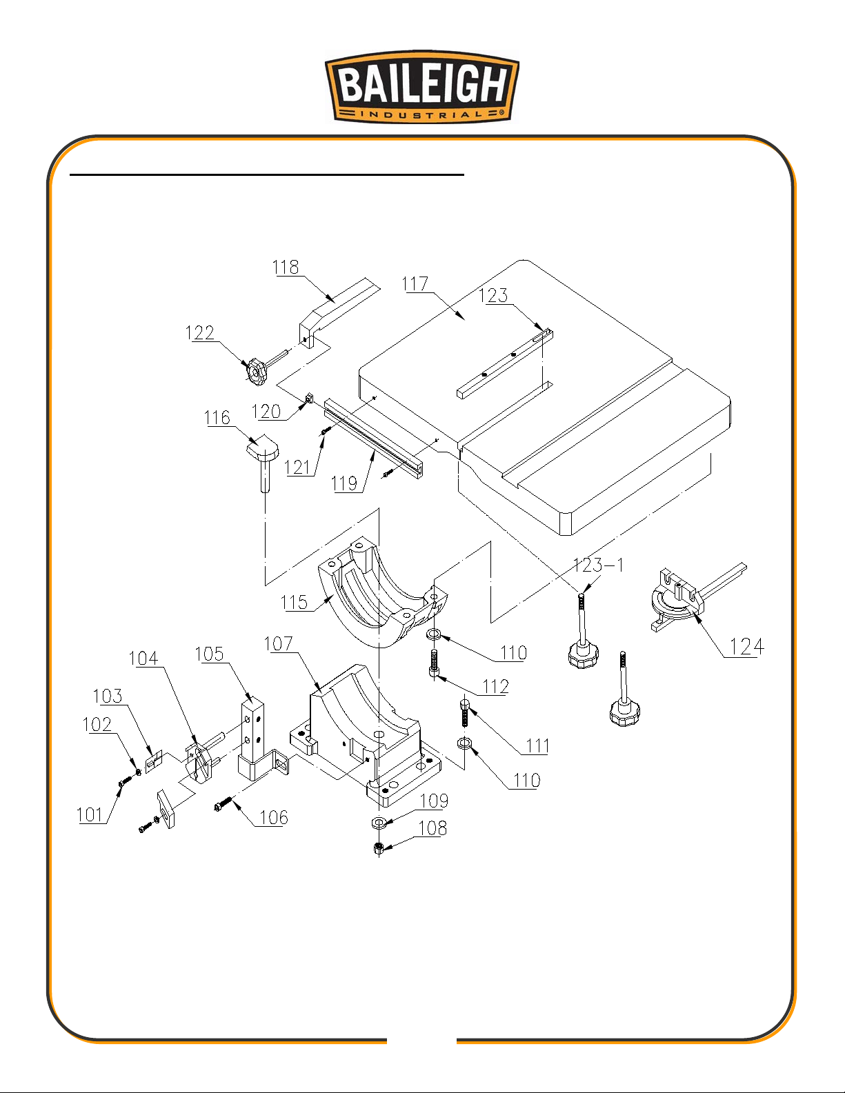
WORK TABLE ASSEMBLY – BREAKDOWN

43
43
Item
Part No.
Description
Size
Qty.
101
TS-1503051
Socket Hex Cap Screw
M6*1.0P*20mm
2
102
TS-1550041
Flat Washer
M6
2
103
BSV20VS-V2-103
Tungsten Support
2 104
BSV20VS-V2-104
Guide Seat (lower)
1
105
BSV20VS-V2-105
Lower Guide Rod
1 106
TS-1503061
Socket Hex Cap Screw
M6*1.0P*25mm
2
107
BSV20VS-V2-107
Trunnion Base
1 108
TS-2311101
Hex Nut
M10
1
109
TS-1550071
Flat Washer
M10
1
110
TS-1550061
Flat Washer
M8
4
111
TS-1490031
Hex Cap Screw
M8*1.25P*20mm
4
112
TS-1504041
Socket Hex Cap Screw
M8*1.25P*20mm
4
115
BSV20VS-V2-115
Trunnion
1 116
BSV20VS-V2-116
Lock plate
1 117
BSV24VS-V2-117
Table
1 118
BSV24VS-V2-118
Fence
1
119
BSV20VS-V2-119
Fence Rail
1 120
BSV20VS-V2-120
T - Block
M12
1
121
TS-1504041
Socket Hex Cap Screw
M8x20mm
2
122
BSV20VS-V2-122
Lock Screw
1 123
BSV24VS-V2-123
Table Insert
1 123-
BSV24VS-V2-123-1
Plastic Knob
2 124
BSV24VS-V2-118
Miter Gauge Assembly
1
Work Table Assembly – Part List

44
44
LOWER WH EEL SET ASSEMBLY – BREAKDOWN

45
45
Item
Part No.
Description
Size
Qty.
201
BSV24VS-V2-201
Rubber ring
500mm
2
202
BSV24VS-V2-202
Lower Wheel
1 202-1
BSV24VS-V2-202-1
Saw Blade (not show)
1 203
TS-2311201
Hex nut
M20
1
204
TS-2360201
Flat Washer
M20
1
205
BSV24VS-V2-205
Key
7x7mm
206
BSV24VS-V2-206
Lower Wheel Shaft
207
BSV24VS-V2-207
Key
7x7x46mm
208
BB6206
Ball Bearing
6206
2
209
BSV24VS-V2-209
Bearing Housing
1 210
BSV24VS-V2-210
Special Screw
4
211
BSV24VS-V2-211
Hex Cap Screw
M10x1.5x50mm
4
212
BSV24VS-V2-212
Hex Nut
M28x1.75
2
213
BSV20VS-V2-214
Wheel Pulley
1 213-1
BSV24VS-V2-A63
Belt
A63
2
214
TS-1492031
Hex Cap Screw
M12*1.5*35mm
2
214-1
TS-1540081
Hex nut
M12
2
214-2
TS-2361121
Lock Washer
M12
2
215
BSV20VS-V2-217
Motor Pulley
1 216
TS-1524021
Set Screw
M8*1.25P*10mm
2
3HP/ 220V/ 3Ph/
6P
218
TS-1490041
Hex Cap Screw
M8x1.25x25mm
8
219
BSV24VS-V2-219
Motor Bracket
1 220
TS-1550061
Flat Washer
M8
16
221
TS-1540061
Hex Nut
M8
8
Lower Wheel Set Assembly – Part List
217 BSV24VS-V2-217 Motor
1

46
46
GUIDEP OST ASSEMBL Y – BREAKDOWN

47
47
Item
Part No.
Description
Size
Qty.
501
TS-1503051
Socket Hex Cap Screw
M6-1*20
2
502
TS-1550041
Flat Washer
M6
2
503
BSV20VS-V2-503
Blade Guide
2
504
BSV20VS-V2-504
Blade Guide Bracket Upper
1
506
TS-1503051
Socket Hex Cap Screw
M6-1*20
1
507
BSV20VS-V2-507
Pin
4*6
2
508
BSV20VS-V2-508
Guidepost Clamp Plate
1
509
BSV20VS-V2-509
Guidepost Rack
1
510
BSV20VS-V2-510
Guidepost Bracket
1
511
TS-2361141
Lock Washer
M14
3
512
BSV20VS-V2-512
Lock Knob
1
513
BSV20VS-V2-513
Special Screw
1
514
BSV20VS-V2-514
Guidepost Pinion Gear
1
515
BSV20VS-V2-515
Worm Gear
1
516
BB609ZZ
Bearing
609zz
1
517
BSV20VS-V2-517
Hand Wheel Handle
1
518
BSV20VS-V2-518
Hand Wheel
1
519
BSV20VS-V2-519
Collar
1
519-1
TS-1523011
Set Screw
M6-1*6
1
520
BSV20VS-V2-520
Worm Gear Bracket
1
521
TS-2361061
Lock Washer
M6
1
522
TS-1503051
Socket Hex Cap Screw
M6-1*20
1
523
BSV20VS-V2-523
Blade Guard
1
524
TS-1550061
Flat Washer
M8
4
525
TS-1490021
Hex Cap Screw
M8-1.25*16mm
4
Guidepost Assembly – Part List

48
48
UPPER WHEEL SET ASS EMBLY – BREAKDOWN

49
49
Item
Part No.
Description
Size
Qty.
601
BSV24VS-V2-601
Upper Wheel
620mm
1
601-1
BSV24VS-V2-601-1
Rubber Ring
1 602
TS-2310201
Hex Nut
M20x1.5
1
603
TS1550111
Flat Washer
M20
604
BB6206
Ball Bearing
6206
1
605
BSV24VS-V2-605
Bearing Housing
1 606
BSV24VS-V2-606
Upper Wheel Shaft
1 607
KEY7726
Key
7x7x26mm
1
608
BB6206
Ball Bearing
6206
1
609
BSV20VS-V2-604
Retaining Ring
STW30#
1
610
TS-0060071
Hex Cap Screw
3/8"-16x1-1/2"
2
611
TS-0720091
Lock Washer
3/8"
2
612
BSV20VS-V2-619
Pivot Pin
2 613
TS-1504051
Socket Hex Cap Screw
M8*1.25P*25mm
4
614
TS-1550061
Flat Washer
M8
4
615
BSV20VS-V2-611
Racket Plate
2
616
TS-1523011
Set Screw
M6*1.0P*6mm
2
617
BSV20VS-V2-613
Collar
2 618
BSV20VS-V2-614
Thrust Bearing
2901
2
619
BSV20VS-V2-615
Tensioning Bracket
1 620
BSV24VS-V2-620
Leadscrew Bracket
1 621
TS-1504051
Socket Hex Cap Screw
M8*1.25P*25mm
2
622
TS-1523011
Set Screw
M6*1.0P*6mm
2
623
BSV20VS-V2-616
Tension Leadscrew
1 624
BSV20VS-V2-617
Tensioning Handwheel
1 625
BSV20VS-V2-622
Lock knob w/ Screw (Large)
M10*1.5P
1
626
BSV20VS-V2-623
Lock knob (small)
M10*1.5P
1
627
BSV20VS-V2-624
Tube
1
628
BSV20VS-V2-621
Spring
1 629
BSV20VS-V2-620
Arrow
1
Upper Wheel Set Assembly – Part List

50
50
WELDER ASSEMBLY- BREAKDOWN

51
51
Item
Part No.
Description
Size
Qty.
301
TS-0050171
Hex Cap Screw
1/4"-20*4"
1
302
BSV20VS-V2-302
Transformer Brack et
1
303
TS-130005
Flat Washer
1/4"
2
304
TS-0561011
Hex Nut
1/4"x20
2
305
BSV20VS-V2-305
Limit Switch
1
306
TS-1503061
Socket Head Cap Screw
M6-1*25
1
307
TS-1503021
Socket Head Cap Screw
M6-1*10
2
308
BSV20VS-V2-308
Limit Switch Bracket
1
309
BSV20VS-V2-309
Sliding Block
1
310
BSV20VS-V2-310
Welding Clamp Left
1
311
BSV20VS-V2-311
Welding Jaw Left
1
312
TS-1503031
Socket Head Cap Screw
M6-1*12
1
313
BSV20VS-V2-313
E-Clip
4mm
1
314
BSV20VS-V2-314
Shaft
1
315
BSV20VS-V2-315
Clamp Lever
1
316
TS-1503031
Socket Head Cap Screw
M6-1*12
1
317
BSV20VS-V2-317
Sliding Block Base
1
318
TS-1503041
Socket Head Cap Screw
M6-1*16
1
319
BSV20VS-V2-318
Grinder Cover
1
320
TS-1540041
Hex Nut
M6
1
321
TS-1550041
Flat Washer
6mm
1
322
BSV20VS-V2-322
Grinding Wheel
DIA 2-1/2”
1
323
TS-1550041
Flat Washer
6mm
1
324
BSV20VS-V2-324
Grinder Motor
1/8HP 220V 1PH
1
324-1
BSV20VS-V2-324-1
Capacitor
3Mf250V
1
325
BSV20VS-V2-325
ON/OFF Switch
1
326
TS-1514021
Socket Head Flat Screw
M6-1*16
1
327
TS-1514031
Socket Head Flat Screw
M6-1*20
1
328
BSV20VS-V2-328
Welding panel
1
329
BSV20VS-V2-329
Clamp pressure Knob
1
330
BSV20VS-V2-330
E-Clip
4mm
1
331
BSV20VS-V2-331
Clamp Lever
1
332
BSV20VS-V2-332
Shaft
1
Welder Assembly – Part List

52
52
Item
Part No.
Description
Size
Qty.
333
BSV20VS-V2-333
Welding Clamp Right
1
334
BSV20VS-V2-334
Insulating Plate
1
335
TS-1550041
Flat Washer
6mm
1
336
TS-1503051
Socket Head Cap Screw
M6-1*20
1
337
TS-1503051
Socket Head Cap Screw
M6-1*20
1
338
BSV20VS-V2-338
Welding Jaw Right
1
339
TS-1503051
Socket Head Cap Screw
M6-1*20
1
340
TS-1540041
Hex Nut
M6
1
341
TS-1550041
Flat Washer
6mm
1
342
BSV20VS-V2-342
Pressure Cam
1
343
BSV20VS-V2-343
Cam Shaft
1
344
BSV20VS-V2-344
Tension Spring
0.8*25mm
1
345
TS-0207021
Socket Head Cap Screw
1/4-20*1/2
1
346
BSV20VS-V2-346
Bracket
1
347
BSV20VS-V2-347
Annealing Push Button
1
348
BSV20VS-V2-348
Welding Push Button
1
349
BSV20VS-V2-349
Transformer
4.2KVA 220V
1

53
53
ELECTRICAL DIAGRAM

54
54
Item
Part No.
Symbol
Description
1
BSV24VS-V2-EL1
KM1
Contactor (Saw Blade M otor )
2
BSV24VS-V2-EL1
KM2
Contactor (Grinder Motor)
3
BSV20VS-V2-EL3
M2
Grinder Motor
4
BSV24VS-V2-EL4
M1
Saw Blade Motor
5
BSV24VS-V2-EL5
F
Fuse 5A (2pcs)
6
BSV20VS-V2-EL6
P1
Key switch for main Power
7
BSV20VS-V2-EL7
PB1
Off switch
8
BSV20VS-V2-EL8
PB2
Main Motor start Switch
9
BSV20VS-V2-EL9
PB3
Emergency Switch
10
BSV20VS-V2-EL10
S1
Select switch for Cut / Weld function
11
BSV20VS-V2-EL11
R
Relay (VFD Run Signal)
12
BSV20VS-V2-EL12
P
Air Pump
13
BSV20VS-V2-EL13
VR
Variable Speed Knob
Electrical Diagram Part List

55
55
NOTES

56
56
NOTES

57
57
BAILEIGH INDUSTRIAL HOLDINGS LLC
1625 DUFEK DRIVE MANITOWOC, WI 54220
PHONE: 920. 684. 4990 FAX: 920. 684. 3944
www.baileigh.com
 Loading...