


© 2015 Baileigh Industrial, Inc.
OPERATOR’S MANUAL
ROTARY DRAW BENDER
MODEL: RDB-050 (B8000)

Rev. 03/2015
Table of Contents
INTRODUCTION ............................................................................................................. 1
GENERAL NOTES .......................................................................................................... 1
SAFETY INSTRUCTIONS .............................................................................................. 2
SAFETY PRECAUTIONS ............................................................................................... 4
TECHNICAL SPECIFICATIONS ..................................................................................... 6
TECHNICAL SUPPORT ................................................................................................. 6
UNPACKING AND CHECKING CONTENTS .................................................................. 7
TRANSPORTING AND LIFTING .................................................................................... 8
INSTALLATION ............................................................................................................... 8
ASSEMBLY AND SET UP ............................................................................................ 10
GETTING TO KNOW YOUR MACHINE ....................................................................... 11
GENERAL DESIGN DESCRIPTION ............................................................................. 12
OPERATION ................................................................................................................. 13
Bending ..................................................................................................................... 13
Die Selection ............................................................................................................. 14
Die Installation ........................................................................................................... 15
Material Insertion ....................................................................................................... 16
Material Insertion Limitations ..................................................................................... 16
UNDERSTANDING SPRINGBACK .............................................................................. 17
MATERIAL SELECTION ............................................................................................... 17
MATERIAL LAYOUT ..................................................................................................... 18
PIPE AND TUBE BENDING DIAGRAMS ..................................................................... 19
BENDING GLOSSARY ................................................................................................. 20
BENDING SUGGESTIONS .......................................................................................... 21
Aluminum Bending .................................................................................................... 21
Heavy Wall DOM tubing ............................................................................................ 21
LUBRICATION AND MAINTENANCE .......................................................................... 22
TABLES, CHARTS, & DIAGRAMS ............................................................................... 23
Table 1 Standard Pipe Sizes and Schedules ............................................................ 23
Table 2 ARC LENGTH TABLE .................................................................................. 24
Diagram 1 .................................................................................................................. 25
Diagram2 ................................................................................................................... 26
STAND ASSEMBLY PARTS DIAGRAM ....................................................................... 27
Stand Assembly Parts List ......................................................................................... 27
TOP FRAME ASSEMBLY PARTS DIAGRAM .............................................................. 28
Top Frame Assembly Parts List ................................................................................. 29
RATCHET WHEEL ASSEMBLY PARTS DIAGRAM ..................................................... 30
Ratchet Wheel Assembly Parts List ........................................................................... 31
DRIVE LEVER ASSEMBLY PARTS DIAGRAM............................................................ 32
Drive Lever Assembly Parts List ................................................................................ 33

1
1
INTRODUCTION
The quality and reliability of the components assembled on a Baileigh Industrial machine
guarantee near perfect functioning, free from problems, even under the most demanding working
conditions. However if a situation arises, refer to the manual first. If a solution cannot be found,
contact the distributor where you purchased our product. Make sure you have the serial number
and production year of the machine (stamped on the nameplate). For replacement parts refer to
the assembly numbers on the parts list drawings.
Our technical staff will do their best to help you get your machine back in working order.
In this manual you will find: (when applicable)
• Safety procedures
• Correct installation guidelines
• Description of the functional parts of the machine
• Capacity charts
• Set-up and start-up instructions
• Machine operation
• Scheduled maintenance
• Parts lists
GENERAL NOTES
After receiving your equipment remove the protective container. Do a complete visual
inspection, and if damage is noted, photograph it for insurance claims and contact your
carrier at once, requesting inspection. Also contact your distributer and inform them of the
unexpected occurrence. Temporarily suspend installation.
Take necessary precautions while loading / unloading or moving the machine to avoid any
injuries.
Your machine is designed and manufactured to work smoothly and efficiently. Following proper
maintenance instructions will help ensure this. Try and use original spare parts, whenever
possible, and most importantly; DO NOT overload the machine or make any unauthorized
modifications.

2
2
SAFETY INSTRUCTIONS
Note: This symbol refers to useful information throughout the manual.
IMPORTANT
PLEASE READ THIS OPERATORS MANUAL CAREFULLY
It contains important safety information, instructions, and necessary operating
procedures. The continual observance of these procedures will help increase your
production and extend the life of the equipment.
LEARN TO RECOGNIZE SAFETY INFORMATION
This is the safety alert symbol. When you see this symbol on
your machine or in this manual, BE ALERT TO THE
POTENTIAL FOR PERSONAL INJURY!
Follow recommended precautions and safe operating
practices.
UNDERSTAND SIGNAL WORDS
A signal word – DANGER, WARNING, or CAUTION
is used with the safety alert symbol. DANGER
identifies a hazard or unsafe practice that will result in
severe Injury or Death.
Safety signs with signal word DANGER or WARNING are
typically near specific hazards.
General precautions are listed on CAUTION safety signs.
CAUTION also calls attention to safety messages in this
manual.

3
3
SAVE THESE INSTRUCTIONS.
Refer to them often and use them to instruct others.
PROTECT EYES
Wear safety glasses or suitable eye protection
when working on or around machinery.
PROTECT AGAINST NOISE
Prolonged exposure to loud noise can cause impairment or loss of
hearing. Wear suitable hearing protective devices such as ear muffs or
earplugs to protect against objectionable or uncomfortable loud noises.
BEWARE OF CRUSH HAZARD
NEVER place your hands, fingers, or any
part of your body in the die area of this
machine. Be aware of the area on either side
of the dies for crush points created by
material movement.
4
4
BEWARE OF PINCH POINTS
Keep hands and fingers away from the drive
mechanisms, cylinders, ratchets, and other
moving linkage while the machine is in
operation.
KEEP CLEAR OF MOVING OBJECTS
Always be aware of the position of the material and the swing area in
which the material will travel. The material will swing with significant
force. This swing area will create pinch points and the force of the
material movement may cause serious bodily injuries.
SAFETY PRECAUTIONS
Metal working can be dangerous if safe and proper operating procedures are not followed. As
with all machinery, there are certain hazards involved with the operation of the product. Using
the machine with respect and caution will considerably lessen the possibility of personal injury.
However, if normal safety precautions are overlooked or ignored, personal injury to the operator
may result.
Safety equipment such as guards, hold-downs, safety glasses, dust masks and hearing
protection can reduce your potential for injury. But even the best guard won’t make up for poor
judgment, carelessness or inattention. Always use common sense and exercise caution in
the workshop. If a procedure feels dangerous, don’t try it.
REMEMBER: Your personal safety is your responsibility.
WARNING: FAILURE TO FOLLOW THESE RULES MAY RESULT IN
SERIOUS PERSONAL INJURY
1. Only trained and qualified personnel can operate this machine.
2. Make sure guards are in place and in proper working order before operating
machinery.
3. Remove any adjusting tools. Before operating the machine, make sure any adjusting tools
have been removed.

5
5
4. Keep work area clean. Cluttered areas invite injuries.
5. Overloading machine. By overloading the machine you may cause injury from flying parts.
DO NOT exceed the specified machine capacities.
6. Dressing material edges. Always chamfer and deburr all sharp edges.
7. Do not force tool. Your machine will do a better and safer job if used as intended. DO NOT
use inappropriate attachments in an attempt to exceed the machines rated capacity.
8. Use the right tool for the job. DO NOT attempt to force a small tool or attachment to do the
work of a large industrial tool. DO NOT use a tool for a purpose for which it was not
intended.
9. Dress appropriate. DO NOT wear loose fitting clothing or jewelry as they can be caught in
moving machine parts. Protective clothing and steel toe shoes are recommended when
using machinery. Wear a restrictive hair covering to contain long hair.
10. Use eye and ear protection. Always wear ISO approved impact safety goggles. Wear a full-
face shield if you are producing metal filings.
11. Do not overreach. Maintain proper footing and balance at all times. DO NOT reach over or
across a running machine.
12. Stay alert. Watch what you are doing and use common sense. DO NOT operate any tool or
machine when you are tired.
13. Check for damaged parts. Before using any tool or machine, carefully check any part that
appears damaged. Check for alignment and binding of moving parts that may affect proper
machine operation.
14. Observe work area conditions. DO NOT use machines or power tools in damp or wet
locations. Do not expose to rain. Keep work area well lighted. DO NOT use electrically
powered tools in the presence of flammable gases or liquids.
15. Keep children away. Children must never be allowed in the work area. DO NOT let them
handle machines, tools, or extension cords.
16. Store idle equipment. When not in use, tools must be stored in a dry location to inhibit rust.
Always lock up tools and keep them out of reach of children.
17. DO NOT operate machine if under the influence of alcohol or drugs. Read warning
labels on prescriptions. If there is any doubt, DO NOT operate the machine.
18. Keep visitors a safe distance from the work area.

6
6
Maximum Center Line Radius (CLR)*
7" (178mm)
Minimum Center Line Radius (CLR)*
3" (76mm)
Minimum OD
.75" (19mm)
Mild Steel Pipe (Schedule 40)
Call for Details
Stainless Steel Pipe (Schedule 40)
Call for Details
Mild Steel Round Tube (Wall)
2.5" (.120) (63.5mm [3mm])
Aluminum Round Tube (Wall)
2.5" (.120) (63.5mm [3mm])
Stainless Steel Round Tube (Wall)
2" (.120) (50.8mm [3mm])
Chromolly Round Tube (Wall)
2" (.120) (50.8mm [3mm])
Mild Steel Solid Rod
1" (25.4mm)
Mild Steel Square Tube (Wall)
1" (.125) (25.4mm [3.175mm])
Shipping Weight (Lbs.)
300lbs. (136kg)
Shipping Dimensions (L x W x H)
35.5” x 35.5” x 17” (900 x 900 x 430mm)
TECHNICAL SPECIFICATIONS
*CLR will vary based upon actual material and wall thickness.
TECHNICAL SUPPORT
Our technical support department can be reached at sales@machineryhouse.com.au listing
support and the model number in the subject line. Tech Support handles questions on machine
setup, schematics, warranty issues, and individual parts needs: (other than die sets and blades).
List the model number, serial number and contact name and phone number as well as a brief
description of the nature of the contact in the body of the message.
For specific application needs or future machine purchases contact the Sales Department at:
sales@machineryhouse.com.au
Note: The photos and illustrations used in this manual are representative only and
may not depict the actual color, labeling or accessories and may be intended to illustrate
technique only.
Note: The specifications and dimensions presented here are subject to change
without prior notice due to improvements of our products.

7
7
SUFFOCATION HAZARD! Immediately discard any plastic
the machine. They have low flash points and can explode or cause fire.
GAS
UNPACKING AND CHECKING CONTENTS
Your Baileigh machine is shipped complete in one crate. Separate all parts from the packing
material and check each item carefully. Make certain all items are accounted for before
discarding any packing material.
WARNING:
bags and packing materials to eliminate choking and suffocation hazards to children
and animals.
If any parts are missing, do not plug in the power cable, or turn the power switch on
until the missing parts are obtained and installed correctly.
Cleaning
Your machine may be shipped with a rustproof waxy oil coating and grease on the exposed
unpainted metal surfaces. To remove this protective coating, use a degreaser or solvent
cleaner. For a more thorough cleaning, some parts will occasionally have to be removed. DO
NOT USE acetone or brake cleaner as they may damage painted surfaces.
Follow manufacturer’s label instructions when using any type of cleaning product. After cleaning,
wipe unpainted metal surfaces with a light coating of quality oil or grease for protection.
WARNING: DO NOT USE gasoline or other petroleum products to clean
CAUTION: When using cleaning solvents work in a well-ventilated area.
Many cleaning solvents are toxic if inhaled.

8
8
TRANSPORTING AND LIFTING
CAUTION: Lifting and carrying operations should be carried out by skilled
workers, such as a truck operator. Make sure the machine is well balanced. Choose a
location that will keep the machine free from vibration and dust from other machinery.
Keep in mind that having a large clearance area around the machine is important for
safe and efficient working conditions.
Follow these guidelines when lifting:
• The lift truck must be able to lift at least 1.5 – 2 times the machines gross weight.
• Make sure the machine is balanced. While transporting, avoid rough or jerky motion, and
maintain a safe clearance zone around the transport area.
• Use a fork lift with sufficient lifting capacity and forks that are long enough to reach the
complete width of the machine.
• Remove the securing bolts that attach the machine to the pallet.
• Approaching the machine from the side, lift the machine on the frame taking care that there
are no cables or pipes in the area of the forks.
• Move the machine to the required position and lower gently to the floor.
• Level the machine so that all the supporting feet are taking the weight of the machine and no
rocking is taking place.
INSTALLATION
IMPORTANT:
Consider the following when looking for a suitable location to place the machine:
• Overall weight of the machine.
• Weight of material being processed.
• Sizes of material to be processed through the machine.
• Space needed for auxiliary stands, work tables, or other machinery.
• Clearance from walls and other obstacles.
• Maintain an adequate working area around the machine for safety.
• Have the work area well illuminated with proper lighting.

9
9
.31"
(7.87mm)
.50"
(12.7mm)
• Keep the floor free of oil and make sure it is not slippery.
• Remove scrap and waste materials regularly, and make sure the work area is free from
obstructing objects.
• If long lengths of material are to be fed into the machine, make sure that they will not extend
into any aisles.
• LEVELING: The machine should be sited on a level, concrete floor. For stationary machines,
provisions for securing it should be in position prior to placing the machine. The accuracy of
any machine depends on the precise placement of it to the mounting surface.
• FLOOR: This tool distributes a large amount of weight over a small area. Make certain that
the floor is capable of supporting the weight of the machine, work stock, and the operator.
The floor should also be a level surface. If the unit wobbles or rocks once in place, be sure to
eliminate by using shims.
• WORKING CLEARANCES: Take into consideration the size of the material to be
processed. Make sure that you allow enough space for you to operate the machine freely.
• POWER SUPPLY PLACEMENT: The power supply should be located close enough to the
machine so that the power cord is not in an area where it would cause a tripping hazard. Be
sure to observe all electrical codes if installing new circuits and/or outlets.
Anchoring the Machine
• Once positioned, anchor the machine to the floor, as shown in
the diagram, using bolts and expansion plugs that connect
through holes in the base of the stand.
IMPORTANT: If the machine is not anchored to the
floor, it will twist and rotate during bending. It will also be tippy
when loaded with long material.

10
10
ASSEMBLY AND SET UP
WARNING: For your own safety, DO NOT connect the machine to the
power source until the machine is completely assembled and you read and
understand the entire instruction manual.
1. Unpack and remove the machine from the
crate it was shipped in.
2. Install the bender assembly (1, bottom
plate) (full ratchet plate assembly not shown
for clarity), onto the stand using the
fasteners (4 and 5) shown.
3. Remove the pivot bolt and install the anti-springback lever
into the latch plate and re-install and tighten the pivot bolt.
4. Connect the latch spring.
5. Read through the remainder of the manual and become
familiar with the die installation and settings as well as
normal operation.
6. Position the machine as desired following the installation
guidelines.

11
11
I B C E G
D
F
H
A
GETTING TO KNOW YOUR MACHINE

12
12
Item
Description
Function
A graduated scale used to indicates the bend angle
that the spindle is currently positioned at.
Used to grip and hold the material during the
bending process.
Forming Die (shown with a 180°
forming die installed)
The Material is formed to the radius and contour of
this die.
Presses the material into the forming die during
bending. Must match the forming die.
Changes the leverage and the speed of the bending
equals slower speed with greater leverage.
F
Pull Handle Assembly
Supply the bending force to rotate the bending plate.
G
Anti-springback Lever
Disengages the lock pin from the locking teeth.
Pointer indicated the bending degrees on the bend
angle scale.
Supports the bend tooling and frame. Rotates during
the bending process.
A Bend Angle Scale
B Sleeve Holder with Sleeve
C
D Counter Die
E Speed/Leverage Pin
rotation for the ratchet plate. Closer to the plate
H Bend Angle Pointer
I Ratchet Plate
GENERAL DESIGN DESCRIPTION
You have made a practical choice in purchasing the RDB-050 Manual Bending Machine. It has
been carefully built of high quality materials and designed to give many years of efficient
service. The simplicity of design and minimum effort required to operate the machine contributes
towards meeting schedules and producing greater profits.
The RDB-050 is a manually powered “Rotary Draw” bending machine. To bend material, a
bending die and hook sleeve are required. The material is hooked by the hook sleeve and is
powerfully rotated in the clockwise direction. As the bending die rotates, the counter die forces
the material to conform to the radius and shape of the bending die. This machine is capable of
producing 180 degree bends (200 deg. max.) by continuing to pull release and pull the ratchet
handle. Each pull of the ratchet handle produces approximately 4 degrees of movement.
The RDB-050 Bending Machine you have purchased is built of solid steel ensuring maximum
rigidity. Grade 8 bolts throughout provides very high rigidity and stability.
Throughout this manual are listed various safety-related descriptions for attention. These
matters for attention contain the essential information to the operators while operating, and
maintaining. Failure to follow these instructions may result in great damage to the machine or
injury to the operator.

13
13
footwear, and leather gloves to protect from burrs and sharp edges.
A B 1 2 3
OPERATION
CAUTION: Always wear proper eye protection with side shields, safety
Bending
1. Before actually bending, several "dry runs" should be performed to familiarize yourself with
all of the machine functions.
2. Keep hands away from the bending zone.
3. With the drive lever and the ratchet wheel in the home (0°) position, bending or dry running
can take place.
4. Depending on the material size, you will
need to choose bending speed 1, 2, or 3.
Until you are familiar with the machine
always start bending using speed 1. You
can change speeds at any time during a
bend. If it is easy for the user to pull on the
bending handle, then the speed can be
increased if desired.
5. Each pull of the handle equals the degrees
listed below.
a. 4 degrees per pull in speed 1
b. 8 degrees per pull in speed 2
c. 12 degrees per pull in speed 3
d. Increasing speed increases pulling
effort of the bending handle.
When the machine is in the home position, engage the anti-springback lever (A).
Next engage the ratchet release lever (B).
Without material in the machine. Pull on the ratchet wheel clockwise. You will hear a "click"
every time the lever is cycled through one stroke in speed 1. Return the lever counter
clockwise and you will hear another "click". You just engaged another tooth on the ratchet
wheel. Continue though these cycles and you can "bend" or "ratchet” all the way to 200 deg.
If you select speed two, you will hear 2 clicks with each full stroke of the handle, and 3 clicks on
speed three.

14
14
whip around possibly causing injury.
CAUTION: It is important to release pressure gently. If the anti-springback
lever is released without caution, the handle assembly and ratchet wheel can violently
When the desired degree position is reached, the anti-springback lever (A) needs to be
deactivated to release the material. If the machine has a heavy bending load on it, you may
have to pull the bending lever forward to relieve the pressure allowing you to release the
anti-springback lever.
Now that the pressure is released, you can disengage the ratchet release lever (B).
The ratchet wheel is now free to rotate back to the home (0°) position.
To bend with material, go to the next section for instruction on how to choose and install the
bending dies.
After the dies are installed, insert material through the hook sleeve aligning the start of bend
with the "0" mark on the die.
Select a speed and follow the above steps and begin ratcheting the machine until you feel
tension on the pull lever. As your tubing just begins to bend, position your pointer to the "0"
on the decree dial. This will compensate for most of your "springback".
Die Selection
IMPORTANT: Damaged or worn tooling should be replaced before attempting to bend
material. This will ensure that bends are correct and provide a longer life to machine
components.
1. Before any bending can take place, the proper die set must be chosen to match the material
being bent. Example; 1-1/2" diameter tubing requires a die set marked 1-1/2" tube.
2. Two different types of dies are available. 90 degree and 180 degree dies. The 180 degree
dies allow you to bend to a full 180 degrees, and the 90 degree dies will allow you to bend to
90 degrees.
3. "Pipe" and "Tube" are not the same. All of the dies will be marked in actual outside diameter
(OD) of the material. This will relate directly to "Tube" dimensions. For “Pipe” dimensions,
refer to Table #1 near the back of the manual for the “Pipe Size Table” to find the standard
pipe OD dimensions.
Caution: When installing large dies use another person to help load into the machine.

15
15
Die Installation
1. To install the die. Remove all of the pivot pins and install them in their storage area to the left
of the ratchet wheel.
2. Choose either a 90 or 180 degree die set. Locate the dies center hole with the center of the
machine.
3. Install the 1" diameter main die pin through the center and all the way until the snap ring
bottoms out.
4. Next install the 7/8" die drive pin into the holes that line up with the respective machine hole.
5. Locate the proper hook sleeve holder and position it so the center of the assembly lines up
with the centerline radius of the die and install the 3/4" hook pin. There are two different hook
sleeve holders. One for whole number nominal CLR dies (ie: 4.0 clr) and one for fractional
(0.5) increment dies (ie: 4.5 clr).
6. Choose a counter die that matches your bend die and install the 1-1/4" counter die pin so the
gap between the die and the counter die is approximately 1/8". For dies under 3.5 clr, the
3/4" die counterdie pin supplied with the machine will be used.
Correct counter die position is approximately 1/8' away from the forming die.
IMPORTANT: It is critical that ail of the pins are fully seated down to the snap ring. If
you attempt to bend without making sure the pins are fully down machine damage will occur and
this will not be covered under warranty.

16
16
Material Insertion
1. Once the die set is properly installed, the material that matches the die can be inserted (I.E.
1-1/4”tube would go into a die mark DS-**-1250T-R***).
2. With the ratchet wheel in the home (0°) position insert the material through the counter die
and forming die and into the hook sleeve so that the material extends at least 1/4" past the
sleeve or until the until the material is at the position of the desired bend. The start of bend
mark is engraved with an “O” on the top of the die. Once the material is placed properly, the
counter die slide block assembly can be tightened.
Important: Liberally apply lubricant along the counterdie and the 1/2 of the
material that contacts the counter die with a WD-40 style lubricant or equivalent. Do not
lubricate the bending die or the hook sleeve. Lubricating the bending die and hook sleeve will
encourage slipping of material during the bend.
Follow the bending steps to bend the material to the desired degrees.
Material Insertion Limitations
• Using the Material Layout formula, calculate the amount of material that will be pulled
through the die.
• Verify that the material is long enough to provide at least 80% coverage in the counter die at
the end of the bend. This will provide enough material remaining in the counter die to be fully
supported in plastic slide.
• Extreme care must be taken when bending material with an existing bend. There must be
enough straight material to complete the bend. If there is not enough material the bent part
of the material will crash into the counter die and damage the machine and tooling.
IMPORTANT: Orienting your material in this fashion will cause damage to your tooling
and machine!! DO NOT pull bent material into the counter die! Make sure you have enough
straight material on the draw side of the material to create your bend.

17
17
potentially hazardous to operator or
personnel working nearby.
UNDERSTANDING SPRINGBACK
Springback can be difficult to understand. As material is bent, the materials yield strength resists
being formed. As a final degree is reached, the machine will have enough power to hold the
bend at a set degree, but as the pressure of the machine is released, the material has a
resistance built in, so it “springs back”
Springback will vary with every size, type and wall thickness, so it will never be consistent from
size to size.
The best way to determine a materials springback is to do sample bends to 90 degrees until a
perfect 90 is obtained.
• At that point document the actual machine degrees.
• Full manual mode is the best place to do these tests.
• Use the overbend amount and enter that value into the springback field.
MATERIAL SELECTION
CAUTION: It must be determined by the customer that materials being
processed through the machine are NOT
When selecting materials keep these instructions in mind:
• Material must be clean and dry. (without oil)
• Material should have a smooth surface so it processes easily.
• Dimensional properties of material must be consistent and not exceed the machine capacity
values.
• Chemical structure of material must be consistent.
• Buy certificated steel from the same vendor when possible.

18
18
MATERIAL LAYOUT
In order to create accurate parts, you will have to layout the material in flat form. First you will
need to determine how much material is used per degree of bend. Use the multiplier table on
Table #3 to determine the arc lengths for the die in use. Or use the following formula:
Alternate arc length formula:
Example: 6.0 clr x2=12 12x3.14=37.699 37.699/360=0.1047” per degree
0.1047x 90 degrees =9.425” of material used for a 90 degree bend.
Once the arc lengths are determined you can begin layout of the material using Diagram #1 as a
reference.
• Diagram #1 shows a simple part bent on the same plane in the same direction.
• Diagram #2 shows bending based off of a centerline in two directions.
• For symmetrical bends, centerline bending is easiest.
• For non-symmetrical bends, continuous one direction bending is best.
• Another way to layout material is to draw them in a 2D computer software program like Auto
Cad. There are many free programs on the internet. In a 2D program you will draw the parts
centerline only with corresponding clr’s. Then you will be able to list individual segments of
the bent part. This data can be directly entered into the control.
• Another program available is BEND-TECH which is a program specifically designed for tube
bending and will give you all of the required data to make a part. This software is available
from Baileigh Industrial.
• Bending with a rotary draw bender requires determining the start of bend point which will line
up with the “0” mark on the die. The portion of the tube toward the hook arm will be locked to
the die, the portion toward the counter die is the draw side and will slide along the counter
die and conform to the dies shape/radius.

19
19
PIPE AND TUBE BENDING DIAGRAMS
L = Arc length (outside)
R = Rise (inside)
D = Tube outside diameter
t = Tube wall thickness
a = First bend arc angle H = Height of offset
b = Second bend arc angle L = Length of offset
A = First tangent R1 = First radius
B = Straight between bends R2 = Second radius
C = Second tangent t = Tube Wall Thickness
D = Tube outside diameter

20
20
Arc Length
The length of material along the centerline of the tubing
Distance in inches from the center of curvature to the centerline
CLR. See Tube Bending and Pipe Bending Diagram
Angle in degrees to which the tube/pipe bends are formed (i.e. 45
degrees, 90 degrees, 180 degrees, etc.)
Bending of a rectangular tube with its short side in the plane of the
tube or pipe bend
Bending of a rectangular tube with its long side in the plane of the
tube or pipe bend
I.D.
Inside diameter of the tube or pipe bends
The minimum straight on the end of pipe bends required by the
bending machine to form the bend
That portion of the pipe or tube that is neither in compression or
tension.
O.D.
Outside diameter in inches of the tube or pipe
The deviation of the horizontal plane of a single pipe bend
the pipe bend
The distortion or flattening of pipe or tube from its normal, round
shape caused by the pipe bending process
Amount of degrees material will return after bending pressure is
released
The straight portion of material on either side of arc of bending
bends. See Tube Bending and Pipe Bending Diagrams.
The point at which the bend starts or ends. See Tube Bending
and Pipe Bending Diagrams.
Wall
The thickness in inches of tubular pipe bending material.
Wrinkles
Waving or corrugation of pipe bending bends in the inner radius.
BENDING GLOSSARY
Centerline Radius (CLR)
Degree
Easy Way (EW)
Hard Way (HW)
Minimum Tangent
Neutral Axis
Out of Plane
Ovality
Springback
axis of the tube bending or pipe bending bends. Abbreviated as
between its tangent points, based on the theoretical center-line of
Tangent
Tangent Point

21
21
BENDING SUGGESTIONS
Aluminum Bending
If bending aluminum, lubrication is very important, if the results are less than desirable with WD40 other lubricants can be used such as:
• Johnson Paste Wax (seems to work the best)
• High Pressure grease
• Highly rich dish soap
• The bronze counter die must be polished and have no aluminum deposits or it will continue
to pick up metal.
• Both steel rollers as well as plastic rollers are available. Plastic rollers are used primarily for
polished aluminum. Steel rollers would be used for non-polished materials.
• Some aluminum will crack as it is being bent, 6061-T6 is very hard and may need to be
annealed or ordered in the “T-0” condition. Aluminum will age harden so if possible try to get
freshly run material.
Heavy Wall DOM tubing
If heavy wall materials are bent to a tight radius, they can tend to slip in the hook arm causing a
poor bend result, below are some suggestions
• Use a vise clamp on the outside of the hook arm to “lock” the material in place.
• Use a piece of two sided coarse emery cloth in between the hook arm and the material, this
works very well.
• In only this application, high pressure grease applied to the DIE GROOVE also helps.

22
22
LUBRICATION AND MAINTENANCE
WARNING: Make sure the electrical disconnect is OFF before working on
the machine.
Maintenance should be performed on a regular basis by qualified personnel.
Always follow proper safety precautions when working on or around any machinery.
• Check daily for any unsafe conditions and fix immediately.
• Check that all nuts and bolts are properly tightened.
• On a weekly basis clean the machine and the area around it.
• Lubricate threaded components and sliding devices.
• Apply rust inhibitive lubricant to all non-painted surfaces.
Note: Proper maintenance can increase the life expectancy of your machine.
• There are two grease zerks on the machine, at the main spindle pivots. Grease these zerks
every month with only two pumps from a standard grease gun.
• Check for any loose or worn parts

23
23
PIPE
SIZES
O.D.
Pipe Schedules and Wall Thickness
5
10
40
80
160
XX STRONG
1/8
0.405
0.400
0.050
0.068
0.095
1/4
0.540
0.500
0.070
0.088
0.119
3/8
0.675
0.500
0.070
0.091
0.126
1/2
0.840
0.700
0.080
0.109
0.147
0.188
0.294
3/4
1.050
0.700
0.080
0.113
0.154
0.219
0.308
1
1.315
0.700
0.110
0.133
0.179
0.250
0.358
1-1/4
1.660
0.700
0.110
0.140
0.191
0.250
0.382
1-1/2
1.900
0.700
0.110
0.145
0.200
0.281
0.400
2
2.375
0.700
0.110
0.154
0.218
0.344
0.436
2-1/2
2.875
0.800
0.120
0.203
0.276
0.375
0.552
TABLES, CHARTS, & DIAGRAMS
Table 1 Standard Pipe Sizes and Schedules

24
24
Degrees
Constant
Degrees
Constant
Degrees
Constant
1
0.0175
31
0.5410
61
1.0645
2
0.0349
32
0.5584
62
1.0819
3
0.0524
33
0.5759
63
1.0994
4
0.0698
34
0.5933
64
1.1168
5
0.0873
35
0.6108
65
1.1343
6
0.1047
36
0.6282
66
1.1517
7
0.1222
37
0.6457
67
1.1692
8
0.1396
38
0.6631
68
1.1866
9
0.1571
39
0.6806
69
1.2041
10
0.1745
40
0.6980
70
1.2215
11
0.1920
41
0.7155
71
1.2390
12
0.2094
42
0.7329
72
1.2564
13
0.2269
43
0.7504
73
1.2739
14
0.2443
44
0.7678
74
1.2913
15
0.2618
45
0.7853
75
1.3088
16
0.2792
46
0.8027
76
1.3262
17
0.2967
47
0.8202
77
1.3437
18
0.3141
48
0.8376
78
1.3611
19
0.3316
49
0.8551
79
1.3786
20
0.3490
50
0.8725
80
1.3960
21
0.3665
51
0.8900
81
1.4135
22
0.3839
52
0.9074
82
1.4309
23
0.4014
53
0.9249
83
1.4484
24
0.4188
54
0.9423
84
1.4658
25
0.4363
55
0.9598
85
1.4833
26
0.4537
56
0.9772
86
1.5007
27
0.4712
57
0.9947
87
1.5182
28
0.4886
58
1.0121
88
1.5356
29
0.5061
59
1.0296
89
1.5531
30
0.5235
60
1.0470
90
1.5705
Table 2 ARC LENGTH TABLE
EXAMPLE: Arc Length = Constant x Bend Radius. Example: 90deg bend with 6” clr
EXAMPLE: 1.575 (from table) x 6” (clr) = 9.45” (Arc Length)
For bends more than 90deg, Constants can be added together.

25
25
Diagram 1

26
26
Diagram2

27
27
Item
Part No.
Description
Qty.
1
M050-6A002
Bottom Plate
1 2 AA-838-16
Sleeve Bushing
1 3 M050-5A005
Stand Weldment
1 4 LW 0.375
3/8” Lockwasher
4 5 0.375-16 x 1.00 HHCS
3/8”-16 x1” Hex Head Cap Screw
4 6 0.250”-20 x 1.00 SHCS
1/4"-20 x 1” Socket Head Cap Screw
1
7
0.250-20 Hex Nut
18/4”-20 Hex Nut
1
STAND ASSEMBLY PARTS DIAGRAM
Stand Assembly Parts List
28
28
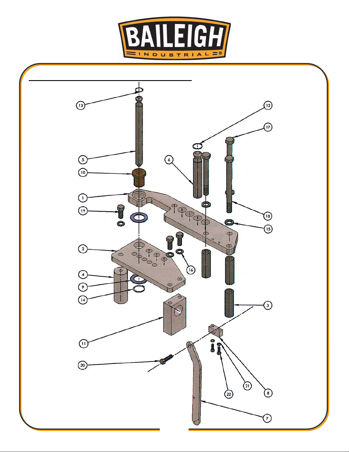
TOP FRAME ASSEMBLY PARTS DIAGRAM

29
29
Item
Part No.
Description
Qty.
1
M050-6A004
Top Plate
1 2 M050-6A005
Pin Plate
1 3 M050-7A002
Spacer Tube
3 4 M050-7A016
Plate Spacer
1
5
M050-7A003
Main Die Pin
1 6 M050-7A005
Counter Die Pin (Large)
1 7 M050-6A010
Spring Back Lever
1 8 M050-6A009
Lever Pivot Block
1 9 M050-7A007
Thrust Washer 1/8”
2
10
M050-7A008
Top Bushing
1
11
M050-6A025
Rectangular Spacer
1
12
1250 Snap Ring
1-1/4” Snap Ring (External)
1
13
1000 Snap Ring
1” Snap Ring (External)
1
14
1500 Snap Ring
1-1/2” Snap Ring (External)
1
15
LW 0.75
3/4" Split Ring Lockwasher
3
16
LW 0.625
5/8" Split Ring Lockwasher
3
17
0.75-10 x 6.50 HHCS
3/4"-10 x 6-1/2” Hex Head Cap Screw
2
18
0.75-10 x 9.00 HHCS
3/4"-10 x 9” Hex Head Cap Screw
1
19
0.625-11 x 1.50 HHCS
5/8"-11 x 1-1/2” Hex Head Cap Screw
3
20
0.500-13 x 1.75 HHCS
1/2"-13 x 1-3/4” Hex Head Cap Screw
1
21
LW 0.3125
5/16" Split Ring Lockwasher
2
22
0.313-18 x 1.00 HHCS
5/16"-18 x 1” Hex Head Cap Screw
2
Top Frame Assembly Parts List

30
30
RATCHET WHEEL ASSEMBLY PARTS DIAGRAM

31
31
Item
Part No.
Description
Qty.
1
M050-6A001
Ratchet Wheel
1 2 M050-6A003
Middle Plate
1 3 M050-6A002
Bottom Plate
1 4 M050-7A016
Plate Spacer
1
5
M050-7A017
Short Tube Spacer
1 6 M050-7A003
Main Die Pin
1 7 M050-7A011
Bumper Pin (Long)
1 8 M050-7A012
Bumper Pin (Short)
1 9 M050-6A013
Latch Drive Bar (Thin)
1
10
M050-7A020
Bumper Pin (Thin)
2
11
M050-6A017
Latch Drive Bar (Lower)
1
12
M050-7A007
Thrust Washer 1/8”
4
13
M050-7A025
Lower Pivot Sleeve
1
14
M050-7A026
Special Hex Nut
1
15
M050-6A025
Rectangular Spacer
1
16
M100-6A019
Degree Sticker
1
17
M050-7A024
Lower Bushing
1
18
1000 Snap Ring
1” Snap Ring (External)
1
19
0750 Snap Ring
3/4” Snap Ring (External)
4
20
LW 0.75
3/4” Split Ring Lockwasher
1
21
M050-6A011
Latch Plate
1
22
0.750-10 x 9.00 HHCS
3/4"-10 x 9” Hex Head Cap Screw
1
23
0.250-20 x 0.75 SHCS
1/4"-20 x 3/4” Socket Head Cap Screw
2
24
0.625-11 x 1.50 HHCS
5/8"-11 x 1-1/2” Hex Head Cap Screw
3
25
LW 0.625
5/8” Split Ring Lockwasher
3
26
M050-6A026
Pointer Block
1
27
DK-1216
Hand Knob
1
28
FF-838-1
Flanged Sleeve Bushing
2
29
0.250-20 x 1.00 SHCS
1/4"-20 x 1” Socket Head Cap Screw
3
30
0.25-20 Hex Nut
1/4"-20 Hex Nut
3
31
PP-1073
3” Spring
3
32
M050-6A027
Pointer
1
Ratchet Wheel Assembly Parts List

32
32
DRIVE LEVER ASSEMBLY PARTS DIAGRAM

33
33
Drive Lever Assembly Parts List
Item
Part No.
Description
Qty.
1
M050-6A013
Latch Drive Bar (Upper)
1 2 M050-6A014
Drive Link
2 3 M050-6A015
Connecting Block
1 4 M050-6A012
Shaft Block
1
5
M050-7A021
Drive Pin
1 6 M050-7A018
Spacer
1 7 M050-6A016
Lock Tab
2 8 M050-7A019
Release Spacer
1 9 M050-7A020
Bumper Pin (Thin)
2
10
M050-6A017
Latch Drive Bar (Lower)
1
11
M050-7A022
Pivot Pin
1
12
M050-7A023
Pivot Pin (Short)
1
13
M050-7A030
Die Drive Pin
1
14
FL-75-4
Flanged Sleeve Bushing
8
15
M050-7A024
Lower Bushing
1
16
M050-7A007
Thrust Washer 1/8”
4
17
AA-838-16
Sleeve Bushing
2
18
M050-7A026
Special Hex Nut
1
20
FF-838-1
Flanged Sleeve Bushing
1
21
AA-838-25
Sleeve Bushing
1
22
M050-7A025
Lower Pivot Sleeve
1
23
0750 Snap Ring
3/4” Snap Ring (External)
6
24
0625 Snap Ring
5/8” Snap Ring (External)
2
25
0.313-18 x 1.00 HHCS
5/16"-18 x 1” Hex Head Cap Screw
8
26
0.313-18 x 0.50 HHCS
5/16"-18 x 1/2” Hex Head Cap Screw
2
27
0.375-16 x 1.75 FHCS
3/8"-16 x 1-3/4” Flat Head Cap Screw
1
28
PP-1073
3” Spring
2
29
0.250-20 x 1.00 SHCS
1/4"-20 x 1” Socket Head Cap Screw
4
30
0.25-20 Hex Nut
1/4"-20 Hex Nut
4

34
34
Distributed By
SYDNEY
(02) 9860 9111
MELBO URNE
(03) 9212 4422
BRIS BANE
(07) 3715 2200
PERT H
(08) 9373 9999

General Machinery Safety Instructions
Machinery House
requires you to read this entire Manual before using this machine.
1. Read the entire Manual before starting
machinery.
not correctly used.
Machinery may cause serious injury if
2. Always use correct hearing protection when
operating machinery.
permanent hearing damage.
Machinery noise may cause
3. Machinery must never be used when tired, or
under the influence of drugs or alcohol.
running machinery you must be alert at all times.
When
4. Wear correct Clothing. At all times remove all loose
clothing, necklaces, rings, jewelry, etc. Long hair
must be contained in a hair net. Non-slip protective
footwear must be worn.
5. Always wear correct respirators around fumes
or dust when operating machinery.
fumes & dust can cause serious respiratory illness.
Dust extractors must be used where applicable.
Machinery
6. Always wear correct safety glasses. When
machining you must use the correct eye protection
to prevent injuring your eyes.
7. Keep work clean and make sure you have good
lighting.
accidents.
Cluttered and dark shadows may cause
8. Personnel must be properly trained or well
supervised when operating machinery.
sure you have clear and safe understanding of the
machine you are operating.
Make
9. Keep children and visitors away. Make sure
children and visitors are at a safe distance for you
work area.
10. Keep your workshop childproof. Use padlocks,
Turn off master power switches and remove start
switch keys.
14. Use correct amperage extension cords.
Undersized extension cords overheat and lose
power. Replace extension cords if they become
damaged.
15. Keep machine well maintained. Keep blades
sharp and clean for best and safest performance.
Follow instructions when lubricating and changing
accessories.
16. Keep machine well guarded. Make sure guards
on machine are in place and are all working
correctly.
17. Do not overreach. Keep proper footing and
balance at all times.
18. Secure workpiece. Use clamps or a vice to
hold the workpiece where practical. Keeping the
workpiece secure will free up your hand to operate
the machine and will protect hand from injury.
19. Check machine over before operating. Check
machine for damaged parts, loose bolts, Keys and
wrenches left on machine and any other conditions
that may effect the machines operation. Repair and
replace damaged parts.
20. Use recommended accessories. Refer to
instruction manual or ask correct service officer
when using accessories. The use of improper
accessories may cause the risk of injury.
21. Do not force machinery. Work at the speed and
capacity at which the machine or accessory was
designed.
22. Use correct lifting practice. Always use the
correct lifting methods when using machinery.
Incorrect lifting methods can cause serious injury.
23. Lock mobile bases. Make sure any mobile bases
are locked before using machine.
11. Never leave machine unattended. Turn power off
and wait till machine has come to a complete stop
before leaving the machine unattended.
12. Make a safe working environment. Do not use
machine in a damp, wet area, or where flammable
or noxious fumes may exist.
13. Disconnect main power before service
machine.
position before re-connecting.
Make sure power switch is in the off
24. Allergic reactions. Certain metal shavings and
cutting fluids may cause an ellergic reaction in
people and animals, especially when cutting as the
fumes can be inhaled. Make sure you know what
type of metal and cutting fluid you will be exposed
to and how to avoid contamination.
25. Call for help. If at any time you experience
difficulties, stop the machine and call you nearest
branch service department for help.

Manual Pipe/Tube Bender Safety Instructions
Machinery House
requires you to read this entire Manual before using this machine.
1. Maintenance. Make sure all moving parts have come
to a complete stop before any inspection, adjustment
or maintenance is carried out.
2. Pipe/Tube Bender Condition. The Pipe/Tube Bender
must be maintained for a proper working condition.
Never operate a Pipe/Tube Bender that has damaged
or worn parts. Scheduled routine maintenance should
performed on a scheduled basis. Check frame, rollers,
springs & formers for cracks or damage. Replace if
necessary.
3. Former Condition. Never operate a Pipe/Tube Bender
with damaged or badly worn Formers. Replace if
required.
4. Hand Hazard. Keep hands away from the Pipe/Tube
Bender under any circumstances while the machine is
in operation mode. Serious injury can occur.
5. Gloves & Glasses. Always wear protective gloves and
approved safety glasses when using this machine.
6. Work area hazards. Keep the area around the
Pipe/Tube Bender clean from oil, tools, objects &
chips. Pay attention to other persons in the area and
know what is going on around the area to ensure
unintended accidents.
7. Guards. Do not operate the Pipe/Tube Bender
without the guards if supplied. The only other area
which needs to be carefully monitored during use is
the rotational area of the formers.
10. Avoiding Entanglement. Pipe/Tube Bender guards
must be used at all times. Tie up long hair and use
the correct hair nets to avoid any entanglement with
the Pipe/Tube Benders moving parts.
11. Trained Operator. This machine must be operated
by authorized and trained personnel.
12. Warning Labels. Take note of any warning labels on
the machine and do not remove them.
13. Material Hazard. Do not bend plastics or other
objects that could shatter. Serious injury can occur.
Make sure your hardness is same throughout the
material. We recommend that you use certified
material.
14. Stopping the Former. Do not stop or slow the
former with your hand or workpiece. Allow the
machine to stop on its own.
15. Secure Pipe/Tube Bender. Make sure you bolt the
machine down so it is secure when in operation.
16. Pinching. Prevent pinching by releasing pressure on
the workpiece when not in use.
17. Call for help. If at any time you experience
difficulties, stop the machine and call you nearest
branch service department for help.
8. Understand the machines controls. Make sure you
understand the use and operation of all controls.
9. Overloading Pipe/Tube Bender. Do not over load
the machine by using material which exceeds the
rated capacity.

Revised Date:
www.machineryhouse.com.au
www.machineryhouse.co.nz
29th January 2019
Plant Safety Program to be read in conjunction with manufactures instructions
O
Use equipment in the correct manner as to avoid parts being ejected out under pressure.
Ensure correct formers are used for the correct job.
HIGH
Always support material properly.
LOW
Wear safety glasses as required.
Check equipment for damage prior to use.
Risk Control Strategies
(Recommended for Purchase / Buyer / User)
Never put any part of your body between moving formers and material.
Do not exceed maximum capacity.
Keep hand away from moving parts.
Wear safety boots.
MEDIUM
OR PUNCTURING
OTHER HAZARDS, EYES.
BCE
CRUSHING
Item
Hazard
Assessment
STRIKING
PLANT SAFETY PROGRAM
No.
Hazard
Identification
Safety officer:
Authorised and signed by:
This program is based upon the Safe Work Australia, Code of Practice - Managing Risks of Plant in the Workplace ( WHSA 2011 No10 )
NEW MACHINERY HAZARD IDENTIFICATION, ASSESSMENT & CONTROL
CUTTING, STABBING
MEDIUM
Use equipment in the correct manner as to avoid parts being ejected out under pressure.
Developed in Co-operation Between A.W.I.S.A and Australia Chamber of Manufactures
Manual Pipe/Tube Benders
Manager:
 Loading...