


OPERATOR’S MANUAL
MAGNETIC DRILL PRESS
MODEL: MD-6000
© 2017 Baileigh Industrial, Inc.
REPRODUCTION OF THIS MANUAL IN ANY FORM WITHOUT WRITTEN APPROVAL OF BAILEIGH INDUSTRIAL, INC.
IS PROHIBITED. Baileigh Industrial, Inc. does not assume and hereby disclaims any liability for any damage or loss
caused by an omission or error in this Operator’s Manual, resulting from accident, negligence, or other occurrence.
Rev. 06/2017
Baileigh Industrial, Inc.
P.O. Box 531
Manitowoc, WI 54221-0531
Phone: 920.684.4990
Fax: 920.684.3944
sales@baileigh.com

Table of Contents
THANK YOU & WARRANTY .......................................................................................... 1
INTRODUCTION ............................................................................................................. 3
GENERAL NOTES .......................................................................................................... 3
SAFETY INSTRUCTIONS .............................................................................................. 4
SAFETY PRECAUTIONS ............................................................................................... 6
Dear Valued Customer: ................................................................................................... 6
TECHNICAL SPECIFICATIONS ..................................................................................... 8
TECHNICAL SUPPORT ................................................................................................. 8
UNPACKING AND CHECKING CONTENTS .................................................................. 9
Cleaning ...................................................................................................................... 9
GETTING TO KNOW YOUR MACHINE ....................................................................... 10
ELECTRICAL ................................................................................................................ 11
DAILY TOOL USE AND CARE REQUIREMENTS ....................................................... 13
MACHINE SET-UP; INSTALLING CUTTERS ............................................................... 14
OPERATION ................................................................................................................. 15
MAINTENANCE AND LUBRICATION .......................................................................... 16
Troubleshooting ................................ ................................ ................................ ......... 17
Adjusting Slides Free Play ......................................................................................... 17
DRILL PARTS DIAGRAM ............................................................................................. 18
Drill Parts List ............................................................................................................ 19
ELECTRICAL SCHEMATIC .......................................................................................... 21

1
1
THANK YOU & WARRANTY
Thank you for your purchase of a machine from Baileigh Industrial. We hope that you find it
productive and useful to you for a long time to come.
Inspection & Acceptance. Buyer shall inspect all Goods within ten (10) days after receipt thereof. Buyer’s
payment shall constitute final acceptance of the Goods and shall act as a waiver of the Buyer’s rights to inspect or
reject the goods unless otherwise agreed. If Buyer rejects any merchandise, Buyer must first obtain a Returned
Goods Authorization (“RGA”) number before returning any goods to Seller. Goods returned without a RGA will be
refused. Seller will not be responsible for any freight costs, damages to goods, or any other costs or liabilities
pertaining to goods returned without a RGA. Seller shall have the right to substitute a conforming tender. Buyer will
be responsible for all freight costs to and from Buyer and repackaging costs, if any, if Buyer refuses to accept
shipment. If Goods are returned in unsalable condition, Buyer shall be responsible for full value of the Goods.
Buyer may not return any special-order Goods. Any Goods returned hereunder shall be subject to a restocking fee
equal to 30% of the invoice price.
Specifications. Seller may, at its option, make changes in the designs, specifications or components of the Goods
to improve the safety of such Goods, or if in Seller’s judgment, such changes will be beneficial to their operation or
use. Buyer may not make any changes in the specifications for the Goods unless Seller approves of such changes
in writing, in which event Seller may impose additional charges to implement such changes.
Limited Warranty. Seller warrants to the original end-user that the Goods manufactured or provided by Seller
under this Agreement shall be free of defects in material or workmanship for a period of twelve (12) months from
the date of purchase, provided that the Goods are installed, used, and maintained in accordance with any
instruction manual or technical guidelines provided by the Seller or supplied with the Goods, if applicable. The
original end-user must give written notice to Seller of any suspected defect in the Goods prior to the expiration of
the warranty period. The original end-user must also obtain a RGA from Seller prior to returning any Goods to
Seller for warranty service under this paragraph. Seller will not accept any responsibility for Goods returned without
a RGA. The original end-user shall be responsible for all costs and expenses associated with returning the Goods
to Seller for warranty service. In the event of a defect, Seller, at its sole option, shall repair or replace the defective
Goods or refund to the original end-user the purchase price for such defective Goods. Goods are not eligible for
replacement or return after a period of 30 days from date of receipt. The foregoing warranty is Seller’s sole
obligation, and the original end-user’s exclusive remedy, with regard to any defective Goods. This limited warranty
does not apply to: (a) die sets, tooling, and saw blades; (b) periodic or routine maintenance and setup, (c) repair or
replacement of the Goods due to normal wear and tear, (d) defects or damage to the Goods resulting from misuse,
abuse, neglect, or accidents, (f) defects or damage to the Goods resulting from improper or unauthorized
alterations, modifications, or changes; and (f) any Goods that has not been installed and/or maintained in
accordance with the instruction manual or technical guidelines provided by Seller.
EXCLUSION OF OTHER WARRANTIES. THE FOREGOING LIMITED WARRANTY IS IN LIEU OF ALL OTHER
WARRANTIES, EXPRESS OR IMPLIED. ANY AND ALL OTHER EXPRESS, STATUTORY OR IMPLIED
WARRANTIES, INCLUDING BUT NOT LIMITED TO, ANY WARRANTY OF MERCHANTABILITY OR FITNESS
FOR ANY PARTICULAR PURPOSE ARE EXPRESSLY DISCLAIMED. NO WARRANTY IS MADE WHICH
EXTENDS BEYOND THAT WHICH IS EXPRESSLY CONTAINED HEREIN.
Limitation of Liability. IN NO EVENT SHALL SELLER BE LIABLE TO BUYER OR ANY OTHER PARTY FOR
ANY INCIDENTIAL, CONSEQUENTIAL OR SPECIAL DAMAGES (INCLUDING, WITHOUT LIMITATION, LOST
PROFITS OR DOWN TIME) ARISING FROM OR IN MANNER CONNECTED WITH THE GOODS, ANY BREACH
BY SELLER OR ITS AGENTS OF THIS AGREEMENT, OR ANY OTHER CAUSE WHATSOEVER, WHETHER
BASED ON CONTRACT, TORT OR ANY OTHER THEORY OF LIABILITY. BUYER’S REMEDY WITH RESPECT
TO ANY CLAIM ARISING UNDER THIS AGREEMENT IS STRICTLY LIMITED TO NO MORE THAN THE
AMOUNT PAID BY THE BUYER FOR THE GOODS.

2
2
Force Majuere. Seller shall not be responsible for any delay in the delivery of, or failure to deliver, Goods due to
causes beyond Seller’s reasonable control including, without limitation, acts of God, acts of war or terrorism, enemy
actions, hostilities, strikes, labor difficulties, embargoes, non-delivery or late delivery of materials, parts and
equipment or transportation delays not caused by the fault of Seller, delays caused by civil authorities,
governmental regulations or orders, fire, lightening, natural disasters or any other cause beyond Seller's reasonable
control. In the event of any such delay, performance will be postponed by such length of time as may be reasonably
necessary to compensate for the delay.
Installation. If Buyer purchases any Goods that require installation, Buyer shall, at its expense, make all
arrangements and connections necessary to install and operate the Goods. Buyer shall install the Goods in
accordance with any Seller instructions and shall indemnify Seller against any and all damages, demands, suits,
causes of action, claims and expenses (including actual attorneys’ fees and costs) arising directly or indirectly out
of Buyer’s failure to properly install the Goods.
Work By Others; Safety Devices. Unless agreed to in writing by Seller, Seller has no responsibility for labor or
work performed by Buyer or others, of any nature, relating to design, manufacture, fabrication, use, installation or
provision of Goods. Buyer is solely responsible for furnishing, and requiring its employees and customers to use all
safety devices, guards and safe operating procedures required by law and/or as set forth in manuals and instruction
sheets furnished by Seller. Buyer is responsible for consulting all operator’s manuals, ANSI or comparable safety
standards, OSHA regulations and other sources of safety standards and regulations applicable to the use and
operation of the Goods.
Remedies. Each of the rights and remedies of Seller under this Agreement is cumulative and in addition to any
other or further remedies provided under this Agreement or at law or equity.
Attorney’s Fees. In the event legal action is necessary to recover monies due from Buyer or to enforce any
provision of this Agreement, Buyer shall be liable to Seller for all costs and expenses associated therewith,
including Seller’s actual attorneys' fees and costs.
Governing Law/Venue. This Agreement shall be construed and governed under the laws of the State of
Wisconsin, without application of conflict of law principles. Each party agrees that all actions or proceedings arising
out of or in connection with this Agreement shall be commenced, tried, and litigated only in the state courts sitting in
Manitowoc County, Wisconsin or the U.S. Federal Court for the Eastern District of Wisconsin. Each party waives
any right it may have to assert the doctrine of “forum non conveniens” or to object to venue to the extent that any
proceeding is brought in accordance with this section. Each party consents to and waives any objection to the
exercise of personal jurisdiction over it by courts described in this section. Each party waives to the fullest extent
permitted by applicable law the right to a trial by jury.
Summary of Return Policy.
• 10 Day acceptance period from date of delivery. Damage claims and order discrepancies will not be accepted
after this time.
• You must obtain a Baileigh issued RGA number PRIOR to returning any materials.
• Returned materials must be received at Baileigh in new condition and in original packaging.
• Altered items are not eligible for return.
• Buyer is responsible for all shipping charges.
• A 30% re-stocking fee applies to all returns.
Baileigh Industrial makes every effort to ensure that our posted specifications, images, pricing and product
availability are as correct and timely as possible. We apologize for any discrepancies that may occur. Baileigh
Industrial reserves the right to make any and all changes deemed necessary in the course of business including but
not limited to pricing, product specifications, quantities, and product availability.
For Customer Service & Technical Support:
Please contact one of our knowledgeable Sales and Service team members at:
(920) 684-4990 or e-mail us at sales@baileigh.com

3
3
INTRODUCTION
The quality and reliability of the components assembled on a Baileigh Industrial machine
guarantee near perfect functioning, free from problems, even under the most demanding
working conditions. However if a situation arises, refer to the manual first. If a solution cannot be
found, contact the distributor where you purchased our product. Make sure you have the serial
number and production year of the machine (stamped on the nameplate). For replacement parts
refer to the assembly numbers on the parts list drawings.
Our technical staff will do their best to help you get your machine back in working order.
In this manual you will find: (when applicable)
• Safety procedures
• Correct installation guidelines
• Description of the functional parts of the machine
• Capacity charts
• Set-up and start-up instructions
• Machine operation
• Scheduled maintenance
• Parts lists
GENERAL NOTES
After receiving your equipment remove the protective container. Do a complete visual
inspection, and if damage is noted, photograph it for insurance claims and contact your
carrier at once, requesting inspection. Also contact Baileigh Industrial and inform them of the
unexpected occurrence. Temporarily suspend installation.
Take necessary precautions while loading / unloading or moving the machine to avoid any
injuries.
Your machine is designed and manufactured to work smoothly and efficiently. Following proper
maintenance instructions will help ensure this. Try and use original spare parts, whenever
possible, and most importantly; DO NOT overload the machine or make any modifications.
Note: This symbol refers to useful information throughout the manual.

4
4
LEARN TO RECOGNIZE SAFETY INFORMATION
This is the safety alert symbol. When you see this symbol on
your machine or in this manual, BE ALERT TO THE
POTENTIAL FOR PERSONAL INJURY!
Follow recommended precautions and safe operating
practices.
UNDERSTAND SIGNAL WORDS
A signal word – DANGER, WARNING, or CAUTION
is used with the safety alert symbol. DANGER
identifies a hazard or unsafe practice that will result in
severe Injury or Death.
Safety signs with signal word DANGER or WARNING are
typically near specific hazards.
General precautions are listed on CAUTION safety signs.
CAUTION also calls attention to safety messages in this
manual.
IMPORTANT
PLEASE READ THIS OPERATORS MANUAL CAREFULLY
It contains important safety information, instructions, and necessary operating
procedures. The continual observance of these procedures will help increase your
production and extend the life of the equipment.
SAFETY INSTRUCTIONS

5
5
SAVE THESE INSTRUCTIONS.
Refer to them often and use them to instruct others.
PROTECT EYES
Wear safety glasses or suitable eye protection
when working on or around machinery.
PROTECT AGAINST NOISE
Prolonged exposure to loud noise can cause impairment or loss of
hearing. Wear suitable hearing protective devices such as ear muffs or
earplugs to protect against objectionable or uncomfortable loud noises.
BEWARE OF PIERCING POINTS
NEVER place Keep hands, fingers, or any part of your body away
from rotating tooling bit.
ENTANGLEMENT HAZARD – ROTATING SPINDLE
Contain long hair, DO NOT wear jewelry or loose fitting clothing.
Wear Eye Protection Read Manual
Wear Ear Protection Wear Respiratory Protection

6
6
SAFETY PRECAUTIONS
Metal working can be dangerous if safe and proper operating procedures are not followed. As
with all machinery, there are certain hazards involved with the operation of the product. Using
the machine with respect and caution will considerably lessen the possibility of personal injury.
However, if normal safety precautions are overlooked or ignored, personal injury to the operator
may result.
Safety equipment such as guards, hold-downs, safety glasses, dust masks and hearing
protection can reduce your potential for injury. But even the best guard won’t make up for poor
judgment, carelessness or inattention. Always use common sense and exercise caution in
the workshop. If a procedure feels dangerous, don’t try it.
REMEMBER: Your personal safety is your responsibility.
Dear Valued Customer:
• All Baileigh machines should be used only for their intended use.
• Baileigh does not recommend or endorse making any modifications or alterations to a
Baileigh machine. Modifications or alterations to a machine may pose a substantial risk of
injury to the operator or others and may do substantial damage to the machine.
• Any modifications or alterations to a Baileigh machine will invalidate the machine's warranty.
PLEASE ENJOY YOUR BAILEIGH MACHINE! ....PLEASE ENJOY IT SAFELY!
1. FOR YOUR OWN SAFETY, READ INSTRUCTION MANUAL BEFORE OPERATING THE
MACHINE. Learn the machine’s application and limitations as well as the specific hazards.
2. Only trained and qualified personnel can operate this machine.
3. Make sure guards are in place and in proper working order before operating
machinery.
4. Turn off main power to the machine and wait for the drill bit, or cutting tool to stop turning
before removing debris, removing or securing the piece part, or changing the position of the
work table.
5. Avoid accidental starts! Be sure switch is off before plugging in. Unplug the drill and keep
finger OFF the switch when moving and positioning.
6. Properly lock the drill bit or cutting tool in the chuck before operating the machine.
WARNING: FAILURE TO FOLLOW THESE RULES MAY RESULT IN
SERIOUS PERSONAL INJURY

7
7
7. DO NOT use electrically powered tools in the presence of flammable gases or liquids. Power
tools create sparks that may ignite flammable materials or gases.
8. Tooling adjustments and maintenance. Always keep tooling sharp and properly adjusted
for optimum performance.
9. Remove any adjusting tools. Before operating the machine, make sure any adjusting tools
have been removed.
10. Keep work area clean. Cluttered areas invite injuries.
11. Overloading machine. By overloading the machine you may cause injury from flying parts.
DO NOT exceed the specified machine capacities.
12. Dressing material edges. Always chamfer and deburr all sharp edges.
13. Do not force tool. Your machine will do a better and safer job if used as intended. DO NOT
use inappropriate attachments in an attempt to exceed the machines rated capacity.
14. Use the right tool for the job. DO NOT attempt to force a small tool or attachment to do the
work of a large industrial tool. DO NOT use a tool for a purpose for which it was not
intended.
15. Dress appropriate. DO NOT wear loose fitting clothing or jewelry as they can be caught in
moving machine parts. Protective clothing and steel toe shoes are recommended when
using machinery. Wear a restrictive hair covering to contain long hair.
16. Use eye and ear protection. Always wear ISO approved impact safety goggles. Wear a full-
face shield if you are producing metal filings.
17. Do not overreach. Maintain proper footing and balance at all times. DO NOT reach over or
across a running machine.
18. Stay alert. Watch what you are doing and use common sense. DO NOT operate any tool or
machine when you are tired.
19. Check for damaged parts. Before using any tool or machine, carefully check any part that
appears damaged. Check for alignment and binding of moving parts that may affect proper
machine operation.
20. Observe work area conditions. DO NOT use machines or power tools in damp or wet
locations. Do not expose to rain. Keep work area well lighted. DO NOT use electrically
powered tools in the presence of flammable gases or liquids.
21. Keep children away. Children must never be allowed in the work area. DO NOT let them
handle machines, tools, or extension cords.
22. Store idle equipment. When not in use, tools must be stored in a dry location to inhibit rust.
Always lock up tools and keep them out of reach of children.
23. DO NOT operate machine if under the influence of alcohol or drugs. Read warning
labels on prescriptions. If there is any doubt, DO NOT operate the machine.
24. Turn off power before checking, cleaning, or replacing any parts.

8
8
25. Be sure all equipment is properly installed and grounded according to national, state, and
local codes.
26. Inspect power and control cables periodically. Replace if damaged or bare wires are
exposed. Bare wiring can kill! DO NOT touch live electrical components or parts.
27. DO NOT bypass or defeat any safety interlock systems.
28. Keep visitors a safe distance from the work area.
TECHNICAL SPECIFICATIONS
Drill Capacity
3/32” – 5/8” (2.5mm – 16mm)
Maximum Stroke
8.25” (210mm)
Cutter Depth
3” (75mm)
Annular Cutter Capacity
1/2" – 2-3/8” (12mm – 60mm)
Spindle Holder
3/4" (19mm)
Magnetic Adhesion
18000N
No Load RPM
260/460
Power Requirements
110V 60hz 1850W (17A)
Shipping Weight
64lbs (29kgs)
TECHNICAL SUPPORT
Our technical support department can be reached at 920.684.4990, and asking for the support
desk for purchased machines. Tech Support handles questions on machine setup, schematics,
warranty issues, and individual parts needs: (other than die sets and blades).
For specific application needs or future machine purchases contact the Sales Department at:
sales@baileigh.com, Phone: 920.684.4990, or Fax: 920.684.3944.
Note: The photos and illustrations used in this manual are representative only and
may not depict the actual color, labeling or accessories and may be intended to illustrate
technique only.
Note: The specifications and dimensions presented here are subject to change
without prior notice due to improvements of our products.
9
9
UNPACKING AND CHECKING CONTENTS
Your Baileigh machine is shipped complete. Separate all parts from the packing material and
check each item carefully. Make certain all items are accounted for before discarding any
packing material.
Cleaning
Your machine may be shipped with a rustproof waxy coating and/or grease on the exposed
unpainted metal surfaces. Fully and completely remove this protective coating using a
degreaser or solvent cleaner. Moving items will need to be moved along their travel path to
allow for cleaning the entire surface. For a more thorough cleaning, some parts will occasionally
have to be removed. DO NOT USE acetone or brake cleaner as they may damage painted
surfaces.
Follow manufacturer’s label instructions when using any type of cleaning product. After cleaning,
wipe unpainted metal surfaces with a light coating of quality oil or grease for protection.
Important: This waxy coating is NOT a lubricant and will cause the machine to
stick and lose performance as the coating continues to dry.
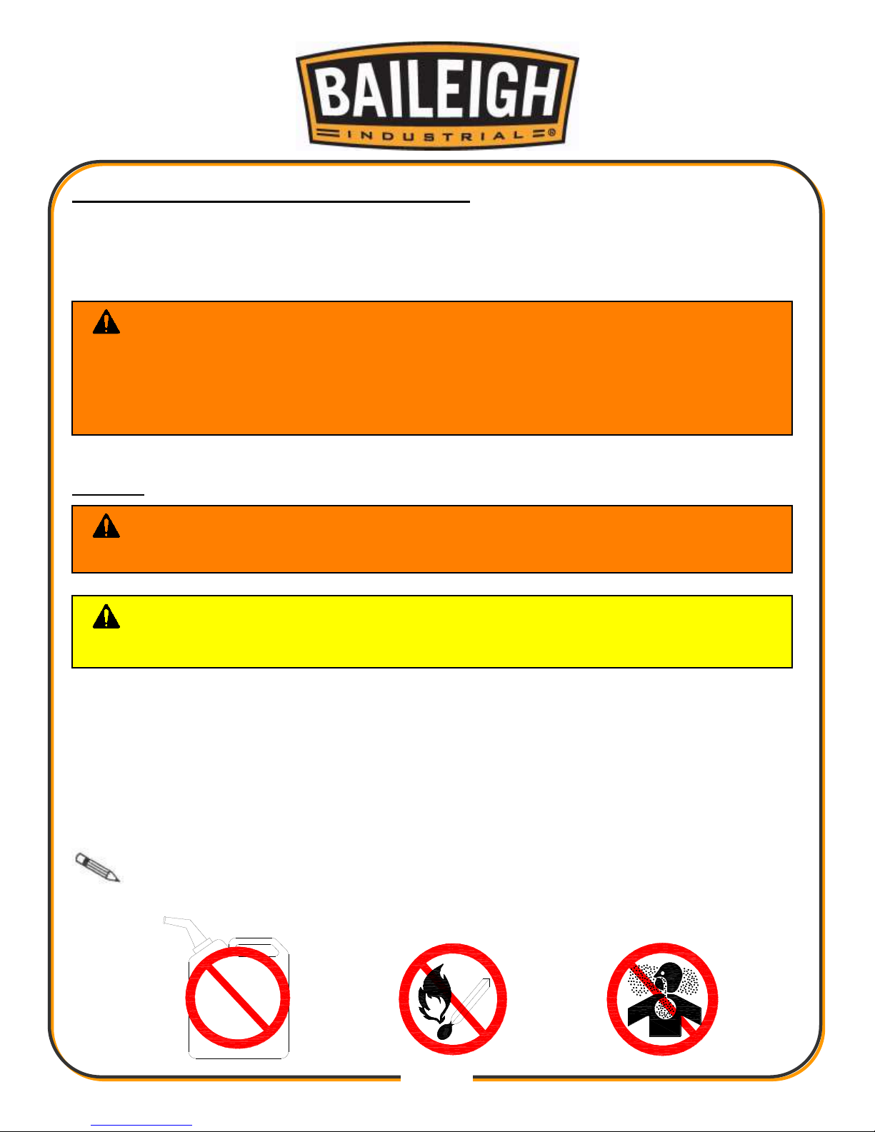
WARNING: SUFFOCATION HAZARD! Immediately discard any plastic
bags and packing materials to eliminate choking and suffocation hazards to children
and animals.
If any parts are missing, DO NOT place the machine into service until the missing
parts are obtained and installed correctly.
WARNING: DO NOT USE gasoline or other petroleum products to clean
the machine. They have low flash points and can explode or cause fire.
CAUTION: When using cleaning solvents work in a well-ventilated area.
Many cleaning solvents are toxic if inhaled.
GAS

10
10
GETTING TO KNOW YOUR MACHINE
Item
Description
A
Forward/Reverse Switch
B
Drill Spindle
C
Speed (RPM) Selector
D
Drill Motor
E
Coolant Reservoir
F
Coolant Flow Valve
G
Slide Adjustment Screws
H
Feed Handle
I
Start/Stop Buttons
J
Electro-Magnet ON/OFF Switch
K
Power Cord
L
Electro-Magnet
B
C
D
F
G
A
E
H
I
J K L
11
11
ELECTRICAL
Power Specifications
Your tool is wired for 220 volts, 60Hz alternating current. Before connecting the tool to the power
source, make sure the machine is cut off from power source.
Before switching on the power, you must check the voltage and frequency of the power to see if
they meet with the requirement, the allowed range for the voltage is ±5%, and for the frequency
is ±1%.
Considerations
• Observe local electrical codes when connecting the machine.
• The circuit should be protected with a time delay fuse or circuit breaker with a amperage
rating slightly higher than the full load current of machine.
• A separate electrical circuit should be used for your tools. Before connecting the motor to the
power line, make sure the switch is in the “OFF” position and be sure that the electric current
is of the same characteristics as indicated on the tool.
• All line connections should make good contact. Running on low voltage will damage the
motor.
• In the event of a malfunction or breakdown, grounding provides a path of least resistance for
electric current to reduce the risk of electric shock. This tool is equipped with an electric cord
having an equipment-grounding conductor and a grounding plug. The plug must be plugged
into a matching outlet that is properly installed and grounded in accordance with all local
codes and ordinances.
CAUTION: HAVE ELECTRICAL UTILITIES CONNECTED TO MACHINE BY
A CERTIFIED ELECTRICIAN!
Check if the available power supply is the same as listed on the machine nameplate.
WARNING: Make sure the grounding wire (green) is properly connected
to avoid electric shock. DO NOT switch the position of the green grounding wire if
any electrical plug wires are switched during hookup.
WARNING: In all cases, make certain the receptacle in question is
properly grounded. If you are not sure, have a qualified electrician check the
receptacle.

12
12
• Improper connection of the equipment-grounding conductor can result in risk of electric
shock. The conductor with insulation having an outer surface that is green with or without
yellow stripes is the equipment-grounding conductor. If repair or replacement of the electric
cord or plug is necessary, do not connect the equipment-grounding conductor to a live
terminal.
• Check with a qualified electrician or service personnel if the grounding instructions are not
completely understood, or if in doubt as to whether the tool is properly grounded.
• Repair or replace damaged or worn cord immediately.
Extension Cord Safety
Extension cord should be in good condition and meet the minimum wire gauge requirements
listed below:
LENGTH
AMP RATING
25ft
50ft
100ft
1-12
16
16
14
13-16
14
12
12
17-20
12
12
10
21-30
10
10
No WIRE GAUGE
An undersized cord decreases line voltage, causing loss of power and overheating. All cords
should use a ground wire and plug pin. Replace any damaged cords immediately.
Power cord connection:
1. Unwrap the power cord and route the cord away from the machine toward the power supply.
a. Route the power cord so that it will NOT become entangled in the machine in any
way.
b. Route the cord to the power supply is a way that does NOT create a trip hazard.
2. Connect the power cord to the power supply and check that the power cord has not been
damaged during installation.
3. When the machine is clear of any obstruction. The main power switch may be turn ON to test
the operation. Turn the switch OFF when the machine is not in operation.

13
13
DAILY TOOL USE AND CARE REQUIREMENTS
• DO NOT touch the cutter while it is in motion. Always follow the personal protection
equipment recommendations while operating this tool.
• Always use both hands to operate the tool.
• Always ensure that the material you are working on is securely clamped.
• Use clamps or other practical way to secure and support the workpiece to a stable platform.
Holding the work by hand or against your body is unstable and may lead to loss of control.
• Do not use tool if switch dose not turn it on or off. Any tool that cannot be controlled with the
switch is dangerous and must be repaired.
• Disconnect the plug from the power source before making any adjustments, changing
accessories, or storing the tool. Such preventive safety measures reduce the risk of starting
the tool accidentally.
• Check for misalignment or binding of moving parts, breakage of parts, and any other
condition that may affect the tools operation. If damaged, have the tool serviced before
using. Many accidents are caused by poorly maintained tools.
• Use only accessories that are recommended by the manufacturer for your model.
Accessories that may be suitable for one tool may become hazardous when used on another
tool.
• Always use safety chain as magnetic mounting can release. Magnetic force will weaken with
usage and increased heat. Allow to cool to regain magnetic force.
• This tool is equipped with an approved cord and plug for its intended use. The green
conductor in the cord is the grounding wire. Never connect this to a live terminal.
• Remove plug from power supply before replacement of the cutter, making adjustments or
other maintenance work.
• We recommend the use of sharp high quality cutters with no visible defects.
• Inspect the machine and cutter before each use and do not use deformed, cracked, worn or
otherwise damaged cutter.
• Ensure the cutter is correctly mounted and do not stop by hand.
• Do not use cutter that do not comply with the characteristics specified in these instructions.
• Ensure that the slides are correctly adjusted before each use. This is essential for proper
and safe operation of the machine.
• Always keep the power cord away from moving parts of the tool.
• When you put the tool away, switch off the motor and ensure that all moving parts have
come to a complete stop.

14
14
MACHINE SET-UP; INSTALLING CUTTERS
1. To insert a cutter, first insert the pilot pin, and then slide the cutter into the adaptor. Align the
proper flat with the locking screw and tighten securely with the supplied hex wrench.
IMPORTANT: Ensure that the locking screw is on a flat of the cutter and not just
against the rounded shank.
2. To remove cutter, reverse the procedure.
3. Ensure that the coolant feed tap is on and coolant feeds properly by pushing the pilot pin. If it
feeds too quickly or slowly, adjust the tap accordingly. Keep the tap closed when not in use.
WARNING: For your own safety, DO NOT connect the machine to the
power source until the machine is completely assembled and you read and
understand the entire instruction manual.

15
15
OPERATION
This machine is designed specifically for drilling
holes in mild steel using the appropriate cutters
and accessories. It should not be modified or
used for any application other than for which it
was intended, including powering other
equipment.
Ensure that the total work area can be viewed
from the operating position. Use barriers to keep
people away.
1. Check that the coolant level and the feed rate
are sufficient to complete the hole to be
drilled. Never operate without cutting coolant.
2. Install the desired bit or cutter for the
operation.
3. Verify that the magnet is clean and free of
metal chips and other dirt and debris. These
will seriously reduce the magnetic adhesion.
IMPORTANT: The drill’s magnetic
adhesion depends on the thickness of the work
piece. 1/2" (12.7mm) is optimum thickness for
safe operation.
4. Position the machine using the pilot pin as an
aid to locate the center of the cut.
5. Secure the safety chain.
6. Switch on the magnet and check that the cutter is still in the correct position and the machine
is securely held to the work piece.
Ensure that the magnet has adhered to the work piece firmly before switch on the drill.
Always use the supply safety chain.
CAUTION: Always wear proper eye protection with side shields, safety
footwear, and leather gloves to protect from burrs and sharp edges.
When handling large heavy material make sure they are properly supported.

16
16
7. Switch the Forward/Reverse switch to the desired direction of rotation.
8. With the motor head in the raised position, switch on the motor and allow it to come up to full
speed.
9. Turn the crank handle to begin cutting use light pressure at first to keep bit from wandering,
and then continue with normal pressure.
Do not force the tool. Let the speed of the cutter do the work. Cutting performance will not
improve by applying more pressure on tool and cutter and motor life will be reduced.
MAINTENANCE AND LUBRICATION
When servicing a tool, use only identical replacement parts. Use of unauthorized parts or failure
to follow maintenance instructions may create a risk of electric shock or injury.
Daily Maintenance
• Inspect the power plug and cord.
• Keep area around machine clear of debris.
• Check daily for any unsafe conditions and fix immediately.
• Check that all nuts and bolts are properly tightened.
Regular Maintenance (Weekly – Monthly)
• Lubricate threaded components and sliding devices.
• Apply rust inhibitive lubricant to all non-painted surfaces.
• Clean the machine and accessories.
Semi-Annually Maintenance
• Check that all fasteners on the machine are tight and secure.
• Lubricate the gear rack and the slide ways so the drill moves up and down smoothly.
• Check the brushes for wear and replace when they reach 1/4" (6.3mm).
WARNING: Make sure the electrical disconnect is OFF before working on
the machine.
Maintenance should be performed on a regular basis by qualified personnel.
Always follow proper safety precautions when working on or around any machinery.

17
17
Troubleshooting
In case of electrical or mechanical malfunction, immediately switch off the tool and disconnect
the plug, excessive sparking may indicate the presence of dirt in the mater or worn out carbon
brushes.
Note: Proper maintenance can increase the life expectancy of your machine.
Adjusting Slides Free Play
Periodically check, lubricate, and adjust as
necessary.
1. To adjust, use the supplied wrench to
loosen the lock nuts (A).
2. Using the supplied hex key, adjust the
screws evenly while moving the handle up
and down so that there is no free play, yet
no blinding anywhere through its range of
travel.
3. Tighten the lock nuts.
A

18
18
DRILL PARTS DIAGRAM

19
19
Drill Parts List
Item
Description
Item
Description
1
Flexible Cable
52
Bearing 6000
2
Switch
53
Bearing 6000
3
Fuse Cap
54
Gear
4
Fuse
55
5*5*35 Key
5
Fuse Holder
56
Gear
6
Motor Starter
57
Bearing 6001
7
Cable Protector
58
Speeder Staff
8
Cable Holder
59
Catch Spring
9
Plate
60
Gear
10
M4*8 Screw
61
Bearing 6004
11
Handle Holder
62
M4*12 Screw
12
Handle
63
Speeder Slide
13
4*10 Key
64
Tube
14
Axle
65
Spring
15
5*15 Key
66
M6*65 Screw
16
Gear
67
Gear Box
17
Stop Plate
68
Bearing 6006
18
M6*10 Screw
69
Catch Spring
19
Cable Protector
70
6*6*14 Key
20
Cable Holder
71
Spindle
21
Machine Holder
72
M10*12 Screw
22
M5*8 Screw
73
Connect
23
Cable Fixer
74
Oil Holder
24
M4*10 Screw
75
O Ring
25
Controller
76
Spring
26
M6*16 Screw
77
Spring Stop
27
Magnetic Switch
78
Catch Spring
28
Magnetic Base
79
M5*35 Screw
29
M5 Screw Nut
80
Motor Holder Cap
30
M5*16 Screw
81
Drill Holder Plate
31
Bearing
82
Electro Induction
32
Bearing
83
Brush Cap
33
Internal Slide
84
Brush

20
20
Item
Description
Item
Description
34
Slide
85
Brush Holder
35
Slide
86
Capacity
36
M5*8 Screw
87
Connect Cap
37
Plate
88
Cable Fixer
38
Rack
89
M4*12 Screw
39
M6*20 Screw
90
Motor Holder
40
Hook
91
Field Core
41
Tank
92
Wind Catcher
42
Valve
93
Bearing 6200
43
M6*10 Screw
94
Motor
44
M5*12 Screw
95
Bearing 6201
45
Out Slide
96
M5*80 Screw
46
M6*12 Screw
97
Safety Strain
47
Drill Holder
98
6mm Hex Wrench
48
M8*30 Screw
99
4mm Hex Wrench
49
Gear Box Cap
100
Chuck Connect
50
Bearing 6000
101
Chuck
51
Gear
102
Chuck Key

21
21
ELECTRICAL SCHEMATIC
KCD4
1
0
L
N
SA
HY57
D2
D3
D4
D1
C2
M1
+
-
F1
L1
L1
L2
KR-06B
JQX-13F-2Z
For.
Rev.

22
22
BAILEIGH INDUSTRIAL, INC. 1625 DUFEK DRIVE MANITOWOC, WI 54220
PHONE: 920. 684. 4990 FAX: 920. 684. 3944
www.baileigh.com
BAILEIGH INDUSTRIAL, INC. 1455 S. CAMPUS AVENUE ONTARIO, CA 91761
PHONE: 920. 684. 4990 FAX: 920. 684. 3944
BAILEIGH INDUSTRIAL LTD. UNIT D SWIFT POINT
SWIFT VALLEY INDUSTRIAL ESTATE, RUGBY
WEST MIDLANDS, CV21 1QH UNITED KINGDOM
PHONE: +44 (0)24 7661 9267 FAX: +44 (0)24 7661 9276
WWW.BAILEIGH.CO.UK
BAILEIGH INDUSTRIAL PTY. LTD.
P.O BOX 1573, 126 MELROSE DRIVE TULLAMARINE,
VIC 3043 AUSTRALIA
PHONE: 011 61 383 743 888
WWW.BAILEIGH.COM.AU
 Loading...