

Page 1
OPERATOR’S
MANUAL
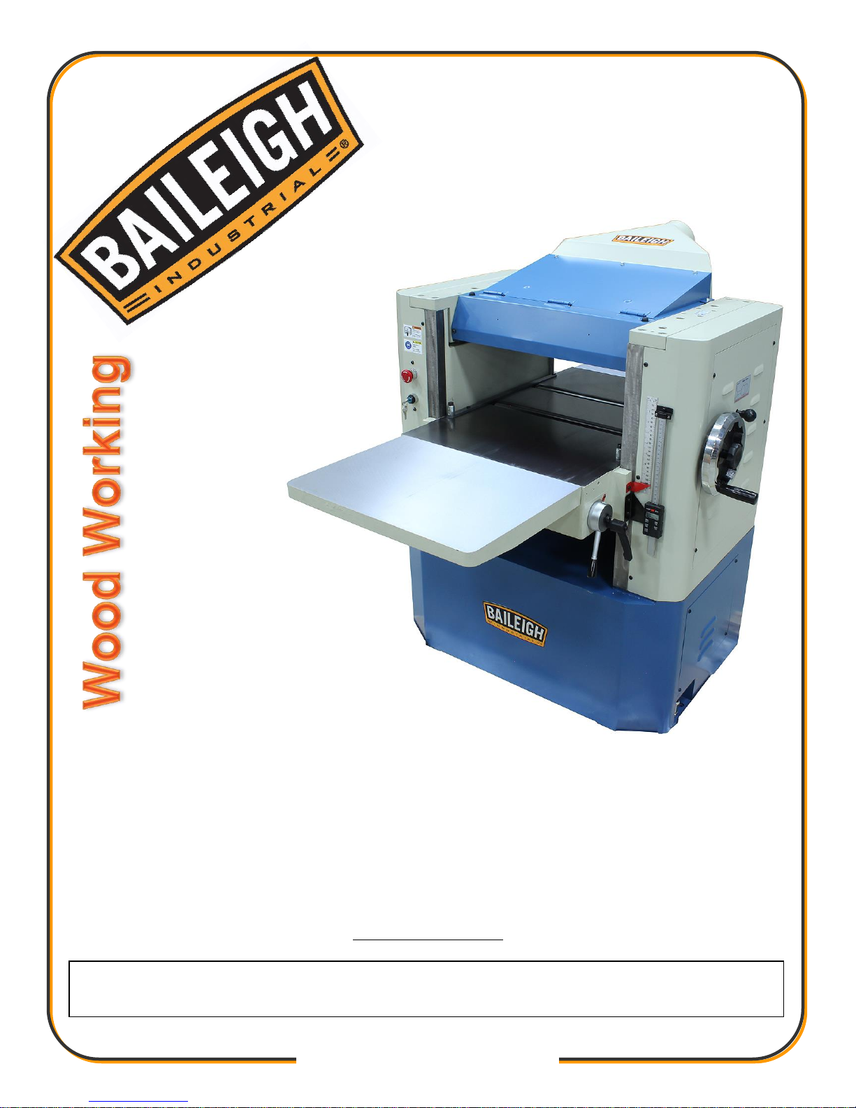
PLANER
MODEL: IP-2008-HD
© 2016 Baileigh Industrial, Inc.
REPRODUCTION OF THIS MANUAL IN ANY FORM WITHOUT WRITTEN APPROVAL OF BAILEIGH INDUSTRIAL, INC.
IS PROHIBITED. Baileigh Industrial, Inc. does not assume and hereby disclaims any liability for any damage or loss
caused by an omission or error in this Operator’s Manual, resulting from accident, negligence, or other occurrence.
Rev. 09/2016
Baileigh Industrial, Inc.
P.O. Box 531
Manitowoc, WI 54221-0531
Phone: 920.684.4990
Fax: 920.684.3944
Page 2

Table of Contents
THANK YOU & WARRANTY .......................................................................................... 1
INTRODUCTION ............................................................................................................. 3
GENERAL NOTES .......................................................................................................... 3
SAFETY INSTRUCTIONS .............................................................................................. 4
SAFETY PRECAUTIONS ............................................................................................... 7
Dear Valued Customer: ................................................................................................... 7
TECHNICAL SPECIFICATIONS ................................................................................... 10
TECHNICAL SUPPORT ............................................................................................... 10
UNPACKING AND CHECKING CONTENTS ................................................................ 11
Cleaning .................................................................................................................... 11
TRANSPORTING AND LIFTING .................................................................................. 12
INSTALLATION ............................................................................................................. 13
Base Levelling ................................ ................................ ................................ ........... 14
Dust Chute Assembly ................................................................................................ 14
Assembly Extension Table ........................................................................................ 15
ELECTRICAL ................................................................................................................ 16
Connecting Power Supply ......................................................................................... 17
INTERNAL COMPONENT IDENTIFICATION ............................................................... 18
OPERATING CONTROLS ............................................................................................ 19
RAISING AND LOWERING TABLE .............................................................................. 19
CHANGING FEED RATE .............................................................................................. 19
TABLE ROLLER ADJUSTMENT .................................................................................. 19
CALIBRATING THE THICKNESS SCALE .................................................................... 20
DIGITAL READOUT ...................................................................................................... 21
SETUP OF FEED ROLLERS, CHIP BREAKER AND PRESSURE BAR ................... 24
Checking Pulley ......................................................................................................... 26
Adjusting Motor Mount ............................................................................................... 26
Adjusting Belt Tension ............................................................................................... 26
Feed Roll Speed Control ........................................................................................... 27
Feed Roll Pressure Adjustment ................................................................................. 27
Table Roller Adjusting ............................................................................................... 28
Adjusting Cutterhead Parallel to Table ...................................................................... 29
Cutterhead and Rollers .............................................................................................. 29
Adjusting Spring Tension of Feed Roller ................................................................... 29
Adjusting Infeed Roller and Outfeed Roller ............................................................... 30
Checking Infeed Roller .............................................................................................. 30
Checking Outfeed Roller ........................................................................................... 30
Checking Height of Chipbreaker ................................................................................ 31
BASIC OPERATION ..................................................................................................... 32
Operation Tips ........................................................................................................... 33
CUT TROUBLESHOOTING .......................................................................................... 33
Feed Restriction ........................................................................................................ 34
Clip Marks
................................................................................................................ 34
Chatter ...................................................................................................................... 34
Snipe ......................................................................................................................... 35
Tapers
....................................................................................................................... 35
Twisting
.................................................................................................................... 35
Page 3

Halted Feeding .......................................................................................................... 35
REPLACING OR ROTATING KNIFE INSERTS ......................................................... 36
MAINTENANCE ............................................................................................................ 37
Cutter Head Removal ................................................................................................ 38
Changing Gearbox Oil ............................................................................................... 41
Control The depth of Cutting ..................................................................................... 42
TROUBLESHOOTING: PLANER OPERATING ............................................................ 44
TROUBLESHOOTING: MECHANICAL AND ELECTRICAL ......................................... 45
PARTS DIAGRAM ........................................................................................................ 47
Parts List ................................................................................................................... 52
Page 4

1
1
THANK YOU & WARRANTY
Thank you for your purchase of a machine from Baileigh Industrial. We hope that you find it
productive and useful to you for a long time to come.
Inspection & Acceptance. Buyer shall inspect all Goods within ten (10) days after receipt thereof. Buyer’s
payment shall constitute final acceptance of the Goods and shall act as a waiver of the Buyer’s rights to inspect or
reject the goods unless otherwise agreed. If Buyer rejects any merchandise, Buyer must first obtain a Returned
Goods Authorization (“RGA”) number before returning any goods to Seller. Goods returned without a RGA will be
refused. Seller will not be responsible for any freight costs, damages to goods, or any other costs or liabilities
pertaining to goods returned without a RGA. Seller shall have the right to substitute a conforming tender. Buyer will
be responsible for all freight costs to and from Buyer and repackaging costs, if any, if Buyer refuses to accept
shipment. If Goods are returned in unsalable condition, Buyer shall be responsible for full value of the Goods.
Buyer may not return any special order Goods. Any Goods returned hereunder shall be subject to a restocking fee
equal to 30% of the invoice price.
Specifications. Seller may, at its option, make changes in the designs, specifications or components of the Goods
to improve the safety of such Goods, or if in Seller’s judgment, such changes will be beneficial to their operation or
use. Buyer may not make any changes in the specifications for the Goods unless Seller approves of such changes
in writing, in which event Seller may impose additional charges to implement such changes.
Limited Warranty. Seller warrants to the original end-user that the Goods manufactured or provided by Seller
under this Agreement shall be free of defects in material or workmanship for a period of twelve (12) months from
the date of purchase, provided that the Goods are installed, used, and maintained in accordance with any
instruction manual or technical guidelines provided by the Seller or supplied with the Goods, if applicable. The
original end-user must give written notice to Seller of any suspected defect in the Goods prior to the expiration of
the warranty period. The original end-user must also obtain a RGA from Seller prior to returning any Goods to
Seller for warranty service under this paragraph. Seller will not accept any responsibility for Goods returned without
a RGA. The original end-user shall be responsible for all costs and expenses associated with returning the Goods
to Seller for warranty service. In the event of a defect, Seller, at its sole option, shall repair or replace the defective
Goods or refund to the original end-user the purchase price for such defective Goods. Goods are not eligible for
replacement or return after a period of 30 days from date of receipt. The foregoing warranty is Seller’s sole
obligation, and the original end-user’s exclusive remedy, with regard to any defective Goods. This limited warranty
does not apply to: (a) die sets, tooling, and saw blades; (b) periodic or routine maintenance and setup, (c) repair or
replacement of the Goods due to normal wear and tear, (d) defects or damage to the Goods resulting from misuse,
abuse, neglect, or accidents, (f) defects or damage to the Goods resulting from improper or unauthorized
alterations, modifications, or changes; and (f) any Goods that has not been installed and/or maintained in
accordance with the instruction manual or technical guidelines provided by Seller.
EXCLUSION OF OTHER WARRANTIES. THE FOREGOING LIMITED WARRANTY IS IN LIEU OF ALL OTHER
WARRANTIES, EXPRESS OR IMPLIED. ANY AND ALL OTHER EXPRESS, STATUTORY OR IMPLIED
WARRANTIES, INCLUDING BUT NOT LIMITED TO, ANY WARRANTY OF MERCHANTABILITY OR FITNESS
FOR ANY PARTICULAR PURPOSE ARE EXPRESSLY DISCLAIMED. NO WARRANTY IS MADE WHICH
EXTENDS BEYOND THAT WHICH IS EXPRESSLY CONTAINED HEREIN.
Limitation of Liability. IN NO EVENT SHALL SELLER BE LIABLE TO BUYER OR ANY OTHER PARTY FOR
ANY INCIDENTIAL, CONSEQUENTIAL OR SPECIAL DAMAGES (INCLUDING, WITHOUT LIMITATION, LOST
PROFITS OR DOWN TIME) ARISING FROM OR IN MANNER CONNECTED WITH THE GOODS, ANY BREACH
BY SELLER OR ITS AGENTS OF THIS AGREEMENT, OR ANY OTHER CAUSE WHATSOEVER, WHETHER
BASED ON CONTRACT, TORT OR ANY OTHER THEORY OF LIABILITY. BUYER’S REMEDY WITH RESPECT
TO ANY CLAIM ARISING UNDER THIS AGREEMENT IS STRICTLY LIMITED TO NO MORE THAN THE
AMOUNT PAID BY THE BUYER FOR THE GOODS.
Page 5

2
2
Force Majuere. Seller shall not be responsible for any delay in the delivery of, or failure to deliver, Goods due to
causes beyond Seller’s reasonable control including, without limitation, acts of God, acts of war or
terrorism, enemy actions, hostilities, strikes, labor difficulties, embargoes, non-delivery or late delivery of materials,
parts and equipment or transportation delays not caused by the fault of Seller, delays caused by civil authorities,
governmental regulations or orders, fire, lightening, natural disasters or any other cause beyond Seller's reasonable
control. In the event of any such delay, performance will be postponed by such length of time as may be reasonably
necessary to compensate for the delay.
Installation. If Buyer purchases any Goods that require installation, Buyer shall, at its expense, make all
arrangements and connections necessary to install and operate the Goods. Buyer shall install the Goods in
accordance with any Seller instructions and shall indemnify Seller against any and all damages, demands, suits,
causes of action, claims and expenses (including actual attorneys’ fees and costs) arising directly or indirectly out
of Buyer’s failure to properly install the Goods.
Work By Others; Safety Devices. Unless agreed to in writing by Seller, Seller has no responsibility for labor or
work performed by Buyer or others, of any nature, relating to design, manufacture, fabrication, use, installation or
provision of Goods. Buyer is solely responsible for furnishing, and requiring its employees and customers to use all
safety devices, guards and safe operating procedures required by law and/or as set forth in manuals and instruction
sheets furnished by Seller. Buyer is responsible for consulting all operator’s manuals, ANSI or comparable safety
standards, OSHA regulations and other sources of safety standards and regulations applicable to the use and
operation of the Goods.
Remedies. Each of the rights and remedies of Seller under this Agreement is cumulative and in addition to any
other or further remedies provided under this Agreement or at law or equity.
Attorney’s Fees. In the event legal action is necessary to recover monies due from Buyer or to enforce any
provision of this Agreement, Buyer shall be liable to Seller for all costs and expenses associated therewith,
including Seller’s actual attorneys' fees and costs.
Governing Law/Venue. This Agreement shall be construed and governed under the laws of the State of
Wisconsin, without application of conflict of law principles. Each party agrees that all actions or proceedings arising
out of or in connection with this Agreement shall be commenced, tried, and litigated only in the state courts sitting in
Manitowoc County, Wisconsin or the u.s. Federal Court for the Eastern District of Wisconsin. Each party waives
any right it may have to assert the doctrine of “forum non conveniens” or to object to venue to the extent that any
proceeding is brought in accordance with this section. Each party consents to and waives any objection to the
exercise of personal jurisdiction over it by courts described in this section. Each party waives to the fullest extent
permitted by applicable law the right to a trial by jury.
Summary of Return Policy.
10 Day acceptance period from date of delivery. Damage claims and order discrepancies will not be accepted
after this time.
You must obtain a Baileigh issued RGA number PRIOR to returning any materials.
Returned materials must be received at Baileigh in new condition and in original packaging.
Altered items are not eligible for return.
Buyer is responsible for all shipping charges.
A 30% re-stocking fee applies to all returns.
Baileigh Industrial makes every effort to ensure that our posted specifications, images, pricing and product
availability are as correct and timely as possible. We apologize for any discrepancies that may occur. Baileigh
Industrial reserves the right to make any and all changes deemed necessary in the course of business including but
not limited to pricing, product specifications, quantities, and product availability.
For Customer Service & Technical Support:
Please contact one of our knowledgeable Sales and Service team members at:
(920) 684-4990 or e-mail us at [email protected]
Page 6

3
3
INTRODUCTION
The quality and reliability of the components assembled on a Baileigh Industrial machine
guarantee near perfect functioning, free from problems, even under the most demanding
working conditions. However if a situation arises, refer to the manual first. If a solution cannot be
found, contact the distributor where you purchased our product. Make sure you have the serial
number and production year of the machine (stamped on the nameplate). For replacement parts
refer to the assembly numbers on the parts list drawings.
Our technical staff will do their best to help you get your machine back in working order.
In this manual you will find: (when applicable)
Safety procedures
Correct installation guidelines
Description of the functional parts of the machine
Capacity charts
Set-up and start-up instructions
Machine operation
Scheduled maintenance
Parts lists
GENERAL NOTES
After receiving your equipment remove the protective container. Do a complete visual
inspection, and if damage is noted, photograph it for insurance claims and contact your
carrier at once, requesting inspection. Also contact Baileigh Industrial and inform them of the
unexpected occurrence. Temporarily suspend installation.
Take necessary precautions while loading / unloading or moving the machine to avoid any
injuries.
Your machine is designed and manufactured to work smoothly and efficiently. Following proper
maintenance instructions will help ensure this. Try and use original spare parts, whenever
possible, and most importantly; DO NOT overload the machine or make any modifications.
Note: This symbol refers to useful information throughout the manual.
Page 7
4
4
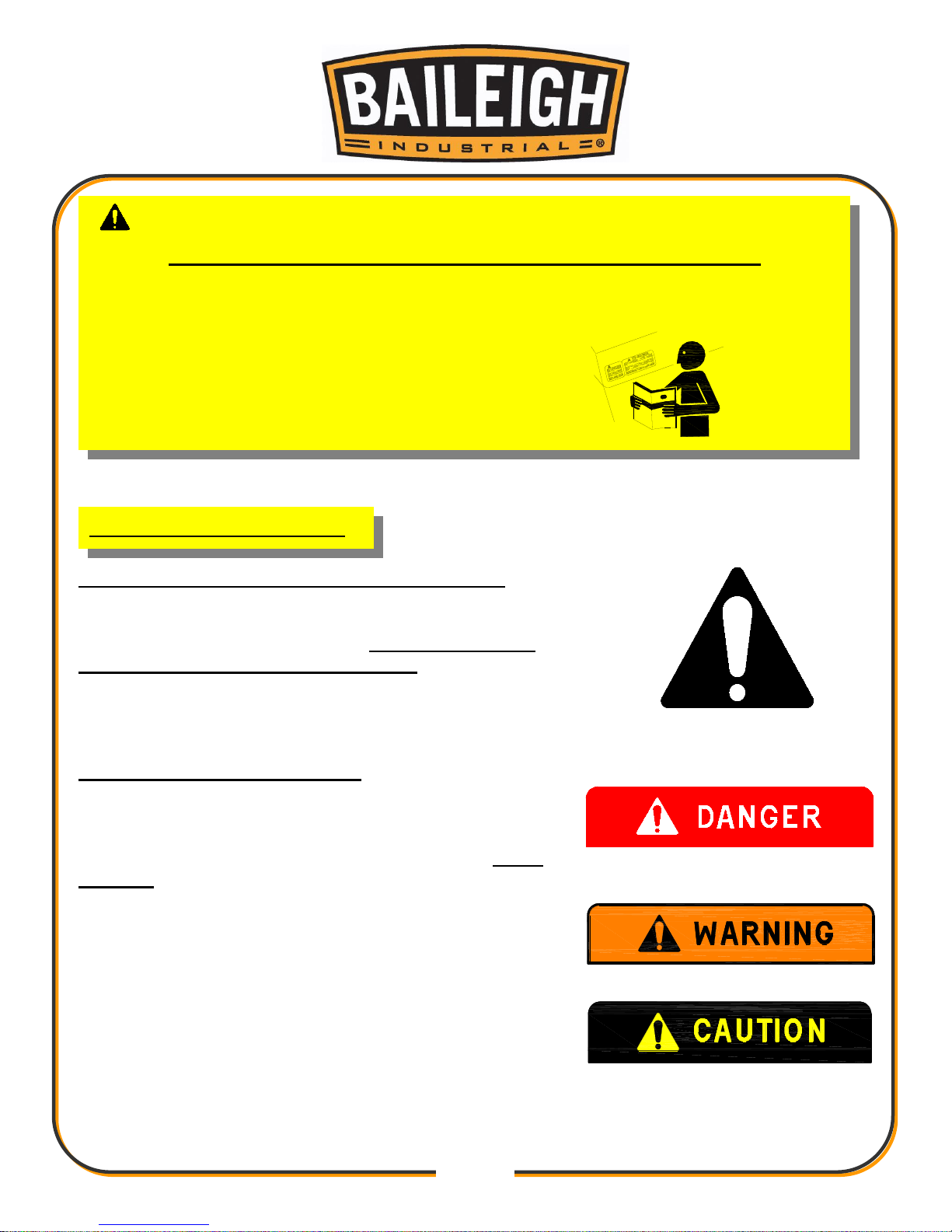
LEARN TO RECOGNIZE SAFETY INFORMATION
This is the safety alert symbol. When you see this symbol
on your machine or in this manual, BE ALERT TO THE
POTENTIAL FOR PERSONAL INJURY!
Follow recommended precautions and safe operating
practices.
UNDERSTAND SIGNAL WORDS
A signal word – DANGER, WARNING, or CAUTION is
used with the safety alert symbol. DANGER identifies a
hazard or unsafe practice that will result in severe Injury
or Death.
Safety signs with signal word DANGER or WARNING are
typically near specific hazards.
General precautions are listed on CAUTION safety signs.
CAUTION also calls attention to safety messages in this
manual.
IMPORTANT
PLEASE READ THIS OPERATORS MANUAL CAREFULLY
It contains important safety information, instructions, and necessary operating procedures.
The continual observance of these procedures will help increase your production and
extend the life of the equipment.
SAFETY INSTRUCTIONS
Page 8
5
5
SAVE THESE INSTRUCTIONS.
Refer to them often and use them to instruct others.
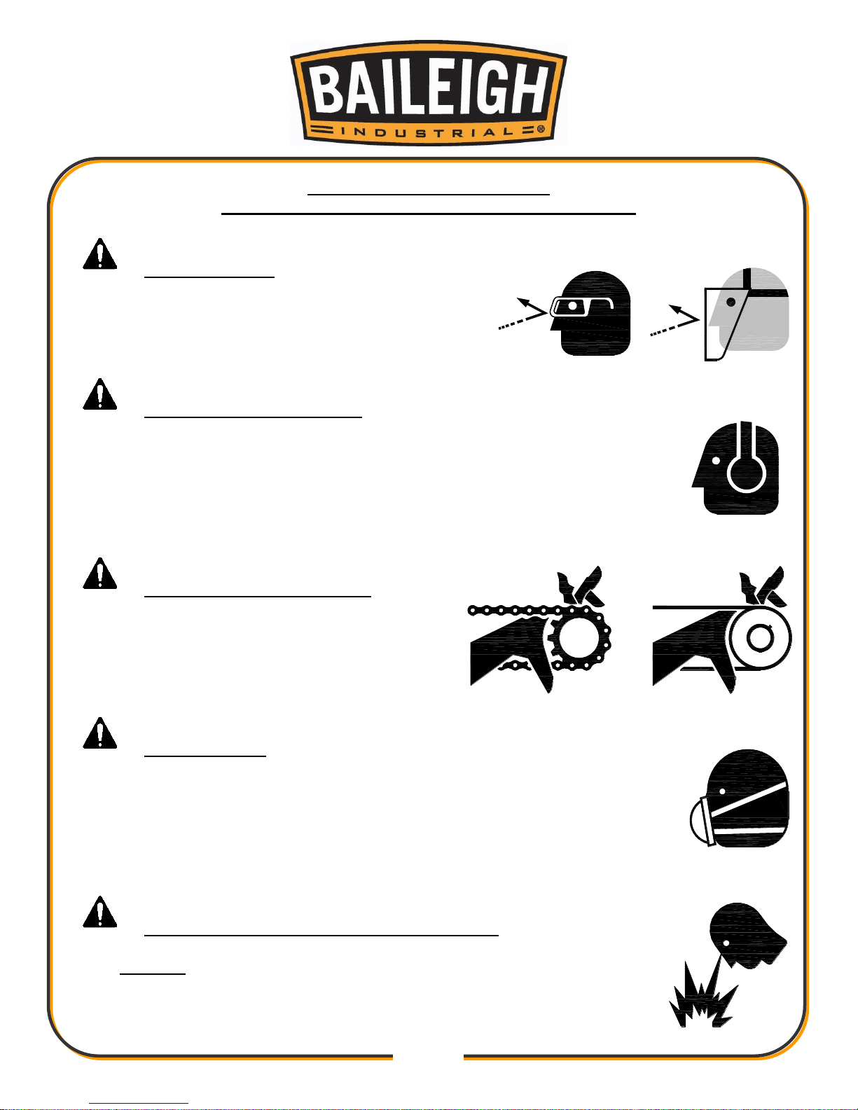
PROTECT EYES
Wear safety glasses or suitable eye protection
when working on or around machinery.
PROTECT AGAINST NOISE
Prolonged exposure to loud noise can cause impairment or loss of
hearing. Wear suitable hearing protective devices such as ear muffs or
earplugs to protect against objectionable or uncomfortable loud noises.
BEWARE OF PINCH POINTS
Keep hands and fingers clear of all potential
pinch points. These include sprockets and
chains along with belts and pulleys.
DUST HAZARD
Wear appropriate dust mask. Dust created while using machinery can
cause cancer, birth defects, and long term respiratory damage. Be aware
of the dust hazards associated with all types of materials.
DUST PARTICLES AND IGNITION SOURCES
DO NOT operate the table saw in areas where explosion risks are
high. Such areas include locations near pilot lights, open flames, or
other ignition sources.
Page 9
6
6
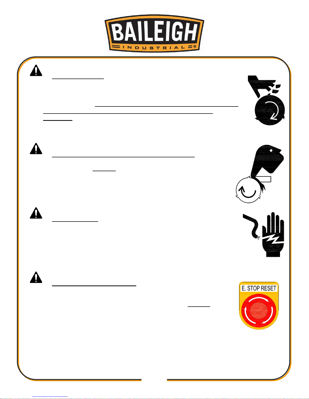
CUTTER HAZARD
Keep hands and fingers away from the rotating cutter blades. These
rotating cutters can be extremely dangerous if you do not follow proper
safety procedures. NEVER place hands directly over or in front of the
cutter. Keep hand at least 6” (150mm) from the cutter while
operating.
ENTANGLEMENT HAZARD – ROTATING BLADES
Contain long hair, DO NOT wear jewelry or loose fitting clothing.
HIGH VOLTAGE
USE CAUTION IN HIGH VOLTAGE AREAS. DO NOT assume the
power to be off.
FOLLOW PROPER LOCKOUT PROCEDURES.
EMERGENCY STOP BUTTON
In the event of incorrect operation or dangerous conditions, the
machine can be stopped immediately by pressing the E-STOP
button. Twist the emergency stop button clockwise (cw) to reset.
Note: Resetting the E-Stop will not start the machine.
Page 10
7
7
SAFETY PRECAUTIONS
Wood working can be dangerous if safe and proper operating procedures are not followed. As
with all machinery, there are certain hazards involved with the operation of the product. Using
the machine with respect and caution will considerably lessen the possibility of personal injury.
However, if normal safety precautions are overlooked or ignored, personal injury to the operator
may result.
Safety equipment such as guards, push sticks, hold-downs, feather boards, goggles, dust
masks and hearing protection can reduce your potential for injury. But even the best guard won’t
make up for poor judgment, carelessness or inattention. Always use common sense and
exercise caution in the workshop. If a procedure feels dangerous, don’t try it.
REMEMBER: Your personal safety is your responsibility.
Dear Valued Customer:
All Baileigh machines should be used only for their intended use.
Baileigh does not recommend or endorse making any modifications or alterations to a
Baileigh machine. Modifications or alterations to a machine may pose a substantial risk of
injury to the operator or others and may do substantial damage to the machine.
Any modifications or alterations to a Baileigh machine will invalidate the machine's warranty.
Please enjoy your Baileigh machine! ....Please enjoy it SAFELY!
1. FOR YOUR OWN SAFETY, READ INSTRUCTION MANUAL BEFORE OPERATING THE
MACHINE. Learn the machine’s application and limitations as well as the specific hazards.
2. Only trained and qualified personnel should operate this machine.
3. Kickback. Become familiar with the term “Kickback” and how it occurs before operating
this planer. Kickback happens when the piece part is thrown towards the operator at a high
rate of speed with the potential for serious injury.
4. Kickback Zone. The path directly behind the end of the in-feed table is referred to as the
“Kickback zone”. NEVER stand or allow others to stand in this area while the machine is
running. Position yourself to one side of the machine while the planer is running.
5. Reaching Inside Planer. To avoid serious personal injury from rotating knives, NEVER
remove guards or reach inside the planer while it is connected to power. Always Follow
proper lockout /tagout procedures.
WARNING: FAILURE TO FOLLOW THESE RULES MAY RESULT IN
SERIOUS PERSONAL INJURY
Page 11

8
8
6. Clearing Jams. To avoid serious personal injury from rotating knives, ALWAYS STOP the
planer and disconnect power before removing a jammed piece part. Always follow proper
lockout/tagout procedures.
7. Using Quality Stock. Inspect the stock over carefully that you intend to plane. NEVER
plane a board that has loose knots, staples, or nails in it. DO NOT plane a piece of stock if
you have any doubts about its structural integrity.
8. Remove any adjusting tools. Before operating the machine, make sure any adjusting tools
have been removed.
9. Dull / Damaged Knives. Use only sharp, undamaged knives to avoid unnecessary kickback
of the piece part. Dull and damaged knives will also affect cut quality.
10. Looking Inside Planer. Wood chips fly around inside the planer at a high rate of speed as it
is running. To avoid possible injury from flying debris, DO NOT look inside the planer while it
is running.
11. Keep work area clean. Cluttered areas invite injuries.
12. Overloading machine. By overloading the machine you may cause injury from flying parts.
DO NOT exceed the specified machine capacities.
13. Dress appropriate. DO NOT wear loose fitting clothing or jewelry as they can be caught in
moving machine parts. Protective clothing and steel toe shoes are recommended when
using machinery. Wear a restrictive hair covering to contain long hair.
14. Use eye and ear protection. Always wear ISO approved impact safety goggles
15. Do not overreach. Maintain proper footing and balance at all times. DO NOT reach over or
across a running machine.
16. Stay alert. Watch what you are doing and use common sense. DO NOT operate any tool or
machine when you are tired.
17. Grain Direction. There is an increased chance of kickback when planing end grain or
against the grain. This could also produce chatter and excessive chip out of the material.
18. Observe work area conditions. DO NOT use machines or power tools in damp or wet
locations. Do not expose to rain. Keep work area well lighted. DO NOT use electrically
powered tools in the presence of flammable gases or liquids.
19. DO NOT bypass or defeat any safety interlock systems.
20. Know the location of the ON - OFF switch and the “E” - STOP button.
21. Keep visitors a safe distance from the work area.
22. In-feed Roller Clearance. The in-feed roller is designed to pull material into the rotating
cutterhead. To avoid serious personal injury, keep hands, jewelry, clothing, and long hair
away from the in-feed roller while operating the machine.
23. Keep children away. Children must never be allowed in the work area. DO NOT let them
handle machines, tools, or extension cords.
Page 12

9
9
24. DO NOT operate machine if under the influence of alcohol or drugs. Read warning
labels on prescriptions. If there is any doubt, DO NOT operate the machine.
25. DO NOT touch live electrical components or parts.
26. Be Sure all equipment is properly installed and grounded according to national, state, and
local codes. If machine is equipped with a three-prong plug, it should be plugged into a
three-hole electrical receptacle. If an adapter is used to accommodate a two-prong
receptacle, the adapter plug must be attached to a known ground. Never remove the third
prong.
27. Inspect power and control cables periodically. Replace if damaged or bare wires are
exposed. Bare wiring can kill!
28. Maintain machine in top condition. Keep clean for best and safest performance. Follow
instructions for lubricating and changing accessories.
29. Reduce the risk of unintentional starting. Make sure switch is in “OFF” position before
plugging in power cord.
30. Never leave machine running unattended. TURN POWER OFF. Don’t leave machine until
it comes to a complete stop.
31. Make sure machine is disconnected from power supply while motor is being mounted,
connected or reconnected.
32. Using Correct Materials. Planing materials other than natural wood fiber can result in
serious personal injury and machine damage. NEVER use this machine for anything except
planing in wood.
33. Warning: The dust generated by certain woods and wood products can be injurious to your
health. Always operate machinery in well ventilated areas and provide for proper dust
removal. Use wood dust collection systems whenever possible.
Page 13
10
10
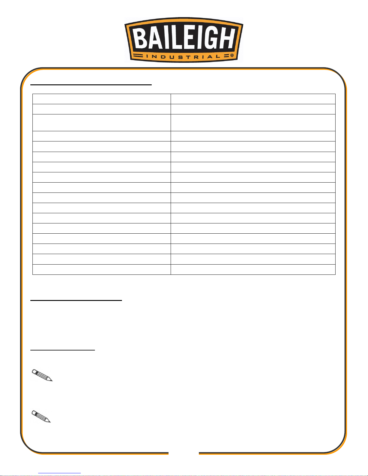
TECHNICAL SPECIFICATIONS
Cutting Capacity (W x H)
20" x 8" (508 x 203mm)
Table Size (Cutting Surface)
20” x 32.375” (508 x 820mm)
Table Size with Wings installed (Cutting
Surface)
20” x 62.375” (508 x 1585mm)
Maximum Depth of Cut
1/8” (3.175mm) @ 22ft/min. (6.7m/min.)
Minimum Material Thickness
1/4” (6.35mm)
Minimum Material Length
9” (220mm)
Segmented Infeed Roller Diameter
3” (76mm)
Outfeed Roller Diameter
3” (76mm)
Feed Rate
22 or 28ft/min. (6.7 or 8.5m/min.)
Cutterhead Speed
4500 RPM
Number Of Knives
5 rows @ 23 = 115
Cutter Head Size
4” (101mm)
Dust Port
5” (127mm)
Minimum CFM for dust collection
900 CFM
Power Supply
220VAC, 3ph, 60hz
Main Motor
7.5Hp (5.5kw), 3Ph, 60Hz, 220VAC, 27A
Shipping Weight (Approx.)
1280 lbs. (581kg)
TECHNICAL SUPPORT
Our technical support department can be reached at 920.684.4990, and asking for the support
desk for purchased machines. Tech Support handles questions on machine setup, schematics,
warranty issues, and individual parts needs: (other than die sets and blades).
For specific application needs or future machine purchases contact the Sales Department at:
[email protected], Phone: 920.684.4990, or Fax: 920.684.3944.
Note: The photos and illustrations used in this manual are representative only and
may not depict the actual color, labeling or accessories and may be intended to illustrate
technique only.
Note: The specifications and dimensions presented here are subject to change
without prior notice due to improvements of our products.
Page 14
11
11
UNPACKING AND CHECKING CONTENTS
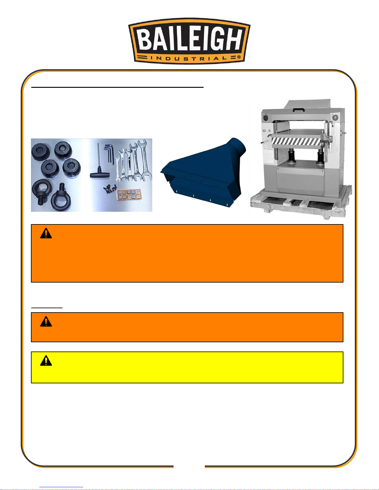
Your Baileigh machine is shipped complete. Separate all parts
from the packing material and check each item carefully. Make
certain all items are accounted for before discarding any packing
material.
Cleaning
Your machine may be shipped with a rustproof waxy coating and/or grease on the exposed
unpainted metal surfaces. Fully and completely remove this protective coating using a
degreaser or solvent cleaner. Moving items will need to be moved along their travel path to
allow for cleaning the entire surface. For a more thorough cleaning, some parts will occasionally
have to be removed. DO NOT USE acetone or brake cleaner as they may damage painted
surfaces.
WARNING: SUFFOCATION HAZARD! Immediately discard any plastic
bags and packing materials to eliminate choking and suffocation hazards to children
and animals.
If any parts are missing, DO NOT place the machine into service until the missing
parts are obtained and installed correctly.
WARNING: DO NOT USE gasoline or other petroleum products to clean
the machine. They have low flash points and can explode or cause fire.
CAUTION: When using cleaning solvents work in a well-ventilated area.
Many cleaning solvents are toxic if inhaled.
Page 15
12
12
Follow manufacturer’s label instructions when using any type of cleaning product. After cleaning,
wipe unpainted metal surfaces with a light coating of quality oil or grease for protection.
Important: This waxy coating is NOT a lubricant and will cause the machine to
stick and lose performance as the coating continues to dry.
TRANSPORTING AND LIFTING
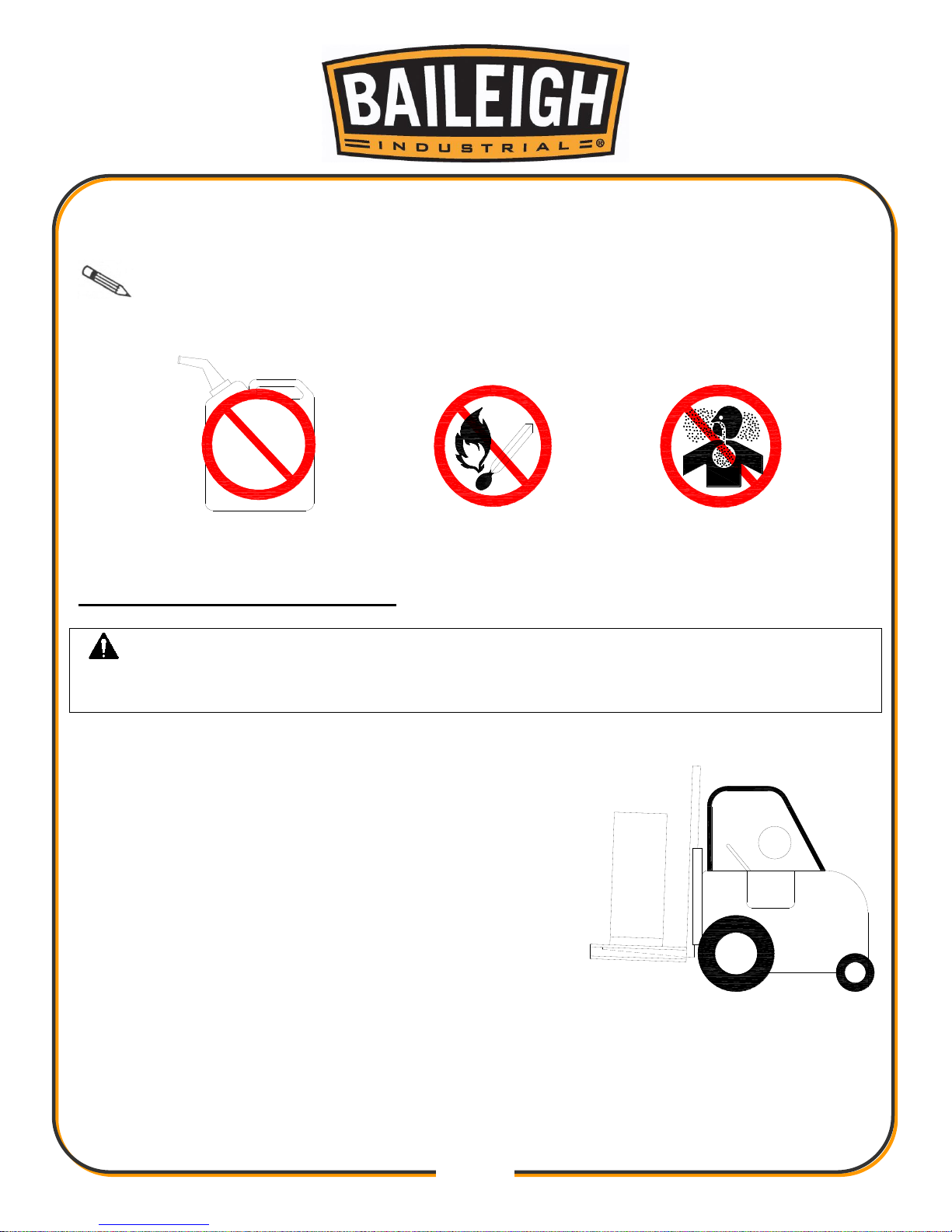
IMPORTANT: Lifting and carrying operations should be carried out by skilled workers,
such as a truck operator, crane operator, etc. If a crane is used to lift the machine, attach the
lifting chain carefully, making sure the machine is well balanced.
Follow these guidelines when lifting with truck or trolley:
The lift truck must be able to lift at least 1.5 – 2 times
the machines gross weight.
Make sure the machine is balanced. While
transporting, avoid rough or jerky motion, and maintain
a safe clearance zone around the transport area.
Use a fork lift with sufficient lifting capacity and forks
that are long enough to reach the complete width of
the machine.
Remove the securing bolts that attach the machine to
the pallet.
Approaching the machine from the side, lift the machine on the frame taking care that there
are no cables or pipes in the area of the forks.
Move the machine to the required position and lower gently to the floor.
Level the machine so that all the supporting feet are taking the weight of the machine and no
rocking is taking place.
GAS
Page 16
13
13
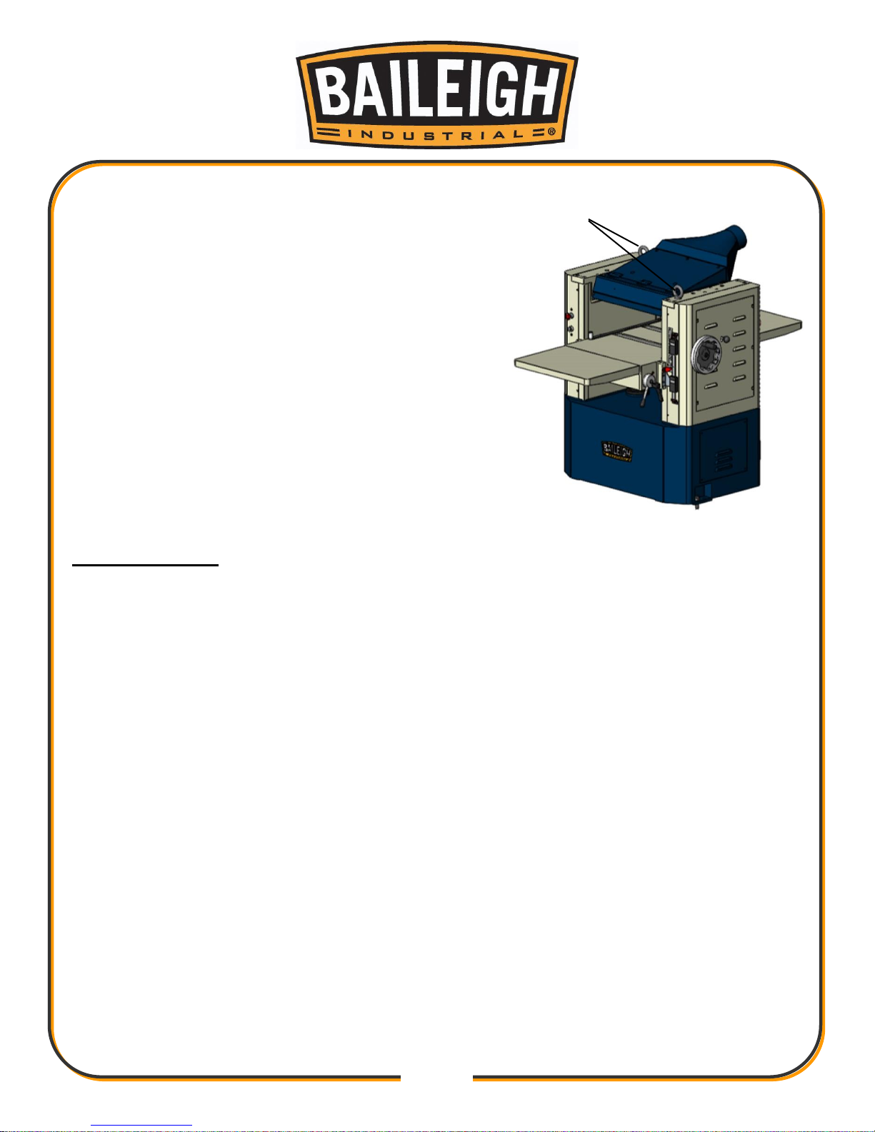
Follow these guidelines when lifting crane or
hoist:
Always lift and carry the machine with the lifting
holes provided at the top of the machine.
Use lift equipment such as straps, chains, capable of
lifting 1.5 to 2 times the weight of the machine.
Take proper precautions for handling and lifting.
Check if the load is properly balanced by lifting it an
inch or two.
Lift the machine, avoiding sudden accelerations or
quick changes of direction.
Locate the machine where it is to be installed, and
lower slowly until it touches the floor.
INSTALLATION
IMPORTANT:
Consider the following when looking for a suitable location to place the machine:
Overall weight of the machine.
Weight of material being processed.
Sizes of material to be processed through the machine.
Space needed for auxiliary stands, work tables, or other machinery.
Clearance from walls and other obstacles.
Maintain an adequate working area around the machine for safety.
Have the work area well illuminated with proper lighting.
Keep the floor free of oil and make sure it is not slippery.
Remove scrap and waste materials regularly, and make sure the work area is free from
obstructing objects.
It is important to maintain free area around the machine, which is required for the working
place. If any long material is machined, it is necessary to have a sufficient room in front of
the machine as well behind it in the places of material input and output.
LEVELING: The machine should be sited on a level, concrete floor. Provisions for securing it
should be in position prior to placing the machine. The accuracy of any machine depends on
the precise placement of it to the mounting surface.
A
Page 17
14
14
FLOOR: This tool distributes a large amount of weight over a small area. Make certain that
the floor is capable of supporting the weight of the machine, work stock, and the operator.
The floor should also be a level surface. If the unit wobbles or rocks once in place, be sure to
eliminate by using shims.
WORKING CLEARANCES: Take into consideration the size of the material to be
processed. Make sure that you allow enough space for you to operate the machine freely.
POWER SUPPLY PLACEMENT: The power supply should be located close enough to the
machine so that the power cord is not in an area where it would cause a tripping hazard. Be
sure to observe all electrical codes if installing new circuits and/or outlets.
Base Levelling
The machine should be sited on a level, concrete floor. The accuracy of any machine depends
on the precise placement of it to the mounting surface. Locate the planer in an area that is level
and provides a solid foundation. Make sure that any potential kickback is not in line with aisles,
doorways, wash stations or other work areas.
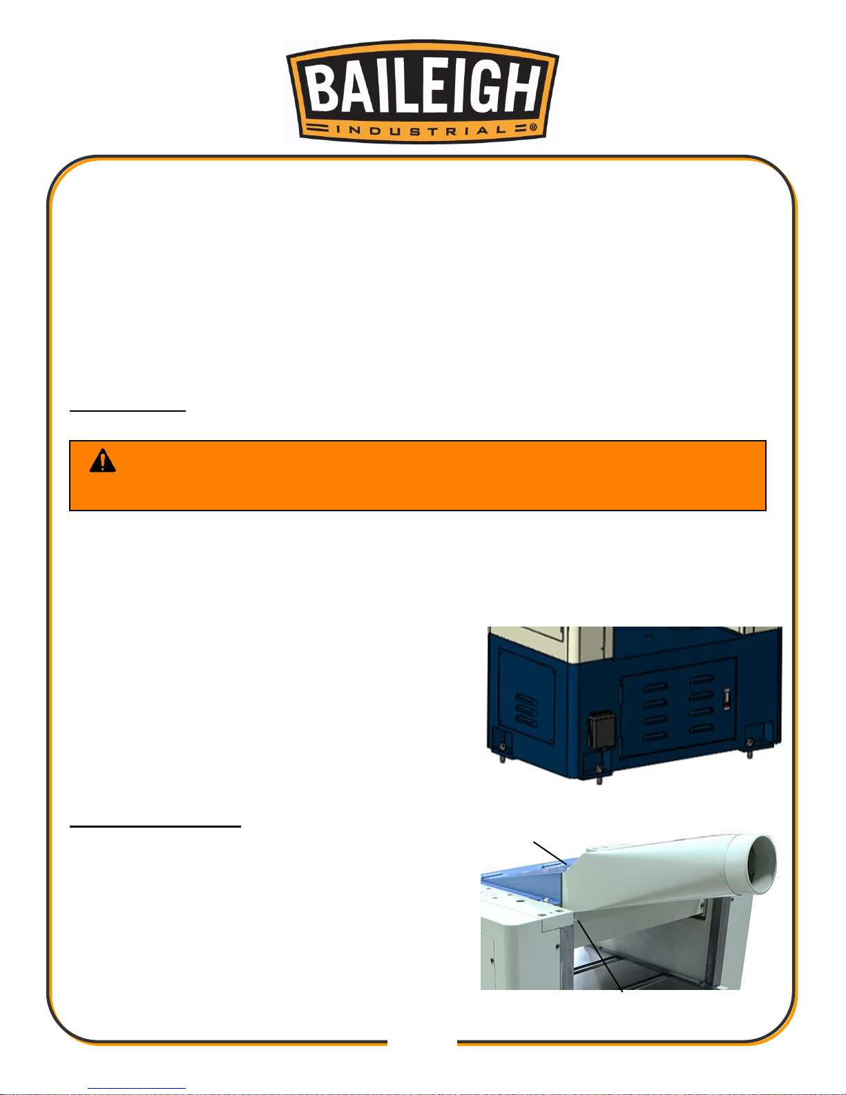
Place the pads under the four leveling bolts
mounted in the base.
Place a level on the table of the planer and adjust
leveling bolts until the machine is resting level.
Tighten the hex nuts against the base of the planer
to keep the leveling bolts from turning.
Dust Chute Assembly
1. Mount the dust chute to the planer hood with six
M6 x 10 hex head screws (A). Three on top and
three under the hood.
2. Make sure the dust collection system has sufficient
capacity and suction for your planer.
3. Always turn on the dust collection system before
starting the planer.
WARNING: Before operating; make sure it is positioned firmly on a solid
level floor. If it tips over on you, it could cause severe injury or death.
A
A
Page 18
15
15
Assembly Extension Table
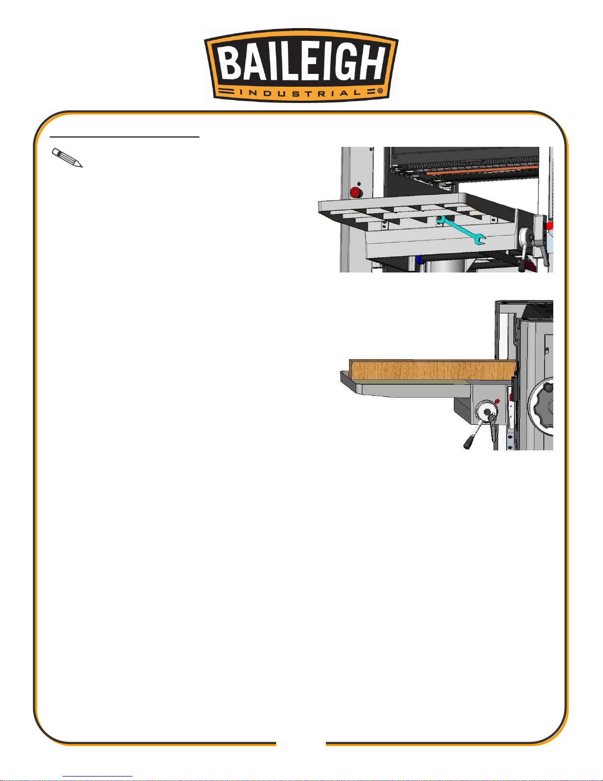
Important: Use and assistant or a
lifting devise to lift and hold the table extension
in position during assembly.
1. Position the extension table up against the
main table and install the three hex head
bolts snug enough to hold the extension in
position.
2. Install the three leveling set screws finger
tight and then loosen 1/2 turn.
3. Place straight edge across the extension and the
main table.
4. Level the extension table to the main table. Use
the hex head bolts to align the table up and down
at the joint. Use the set screws to lift or lower the
outer end of the extension table.
5. When the extension is level, fully tighten the hex
head bolts.
Page 19
16
16
ELECTRICAL
Power Specifications
Your tool is wired for 220 volts, 60Hz alternating current. Before connecting the tool to the power
source, make sure the machine is cut off from power source.
Before switching on the power, you must check the voltage and frequency of the power to see if
they meet with the requirement, the allowed range for the voltage is ±5%, and for the frequency
is ±1%.
Considerations
Observe local electrical codes when connecting the machine.
The circuit should be protected with a time delay fuse or circuit breaker with a amperage
rating slightly higher than the full load current of machine.
A separate electrical circuit should be used for your tools. Before connecting the motor to the
power line, make sure the switch is in the “OFF” position and be sure that the electric current
is of the same characteristics as indicated on the tool.
All line connections should make good contact. Running on low voltage will damage the
motor.
In the event of a malfunction or breakdown, grounding provides a path of least resistance for
electric current to reduce the risk of electric shock. This tool is equipped with an electric cord
having an equipment-grounding conductor and a grounding plug. The plug must be plugged
into a matching outlet that is properly installed and grounded in accordance with all local
codes and ordinances.
WARNING: Baileigh Industrial is not responsible for any damage caused
by wiring up to an alternative 3-phase power source other than direct 3-phase. If you
are using an alternate power source, consult a certified electrician or contact
Baileigh Industrial prior to energizing the machine.
CAUTION: HAVE ELECTRICAL UTILITIES CONNECTED TO MACHINE BY
A CERTIFIED ELECTRICIAN!
Check if the available power supply is the same as listed on the machine nameplate.
WARNING: Make sure the grounding wire (green) is properly connected
to avoid electric shock. DO NOT switch the position of the green grounding wire if
any electrical plug wires are switched during hookup.
Page 20
17
17
Improper connection of the equipment-grounding conductor can result in risk of electric
shock. The conductor with insulation having an outer surface that is green with or without
yellow stripes is the equipment-grounding conductor. If repair or replacement of the electric
cord or plug is necessary, do not connect the equipment-grounding conductor to a live
terminal.
Check with a qualified electrician or service personnel if the grounding instructions are not
completely understood, or if in doubt as to whether the tool is properly grounded.
Repair or replace damaged or worn cord immediately.
Connecting Power Supply
You may either install a plug or “hard-wire” the Planer directly to a control panel.
If you are connecting a plug, use a proper UL/CSA listed 3-pole, 3-wire grounding plug
suitable for 220 Volt operation.
If the Planer is to be hard-wired to a panel, make sure a disconnect switch is readily
available for the operator.
During hard-wiring of the Planer, make sure the fuses have been removed or the breakers
have been tripped in the circuit to which the Planer will be connected. Place a warning
placard on the fuse holder or circuit breaker to prevent it being turned on while the machine
is being wired. Always follow proper lockout /tagout procedures.
1. Lock power out to the circuit that will provide power
to the machine.
2. Remove the electrical box cover.
3. Route the electrical cable into the electrical box.
a. Route the power cord so that it will NOT become
entangled in the machine in any way.
b. Route the power cord so that it will NOT create a
trip hazard.
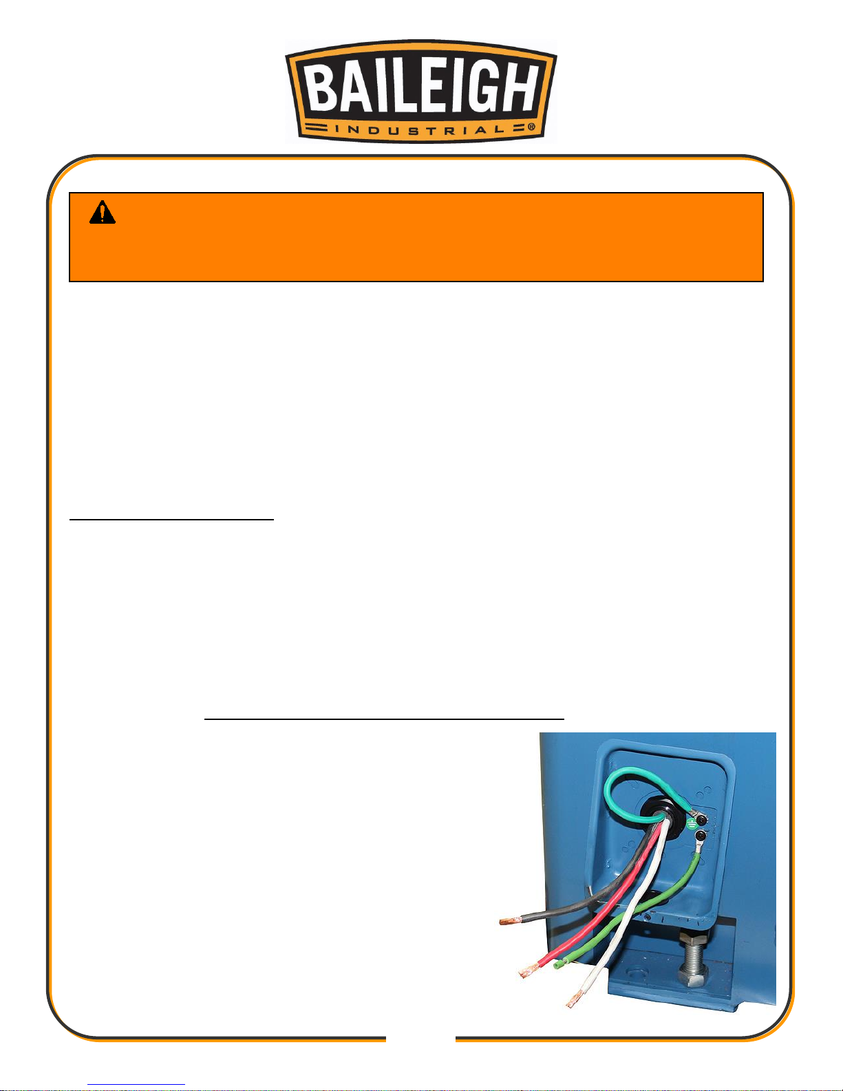
4. Using wire nuts, connect the three power wires to
the wire leads Black, Red, & White. Connect the
ground wire (typically green) to the Green lead.
WARNING: In all cases, make certain the receptacle in question is
properly grounded. If you are not sure, have a qualified electrician check the
receptacle.
Page 21
18
18
5. Check that the power cord has not been damaged during installation.
6. Install the electrical box cover.
7. With power connected and the main disconnect turned ON, the control panel will be lit.
8. Push the table up button to raise the table and the table down button to lower the table.
9. If not, disconnect power to the machine, and switch the Black and White wires. DO NOT
move the ground wire.
INTERNAL COMPONENT IDENTIFICATION
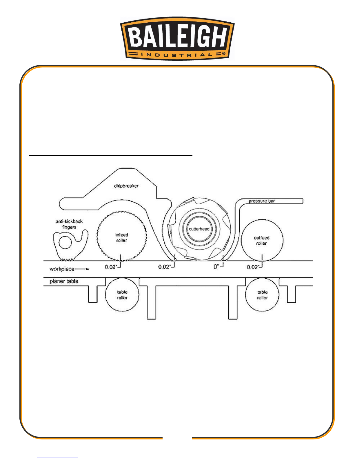
A. Anti-Kickback Fingers: Provide additional safety for the operator.
B. Serrated Infeed Roller: Pushes workpiece toward the cutterhead.
C. Chipbreaker: Breaks off chips created by the cutterhead to prevent tear out and diverts the
chips to the dust port.
D. Cutterhead: Holds the carbide inserts in a longitudinal pattern that plane the workpiece.
E. Pressure Bar: Stabilizes the workpiece as it leaves the cutterhead and assists in deflecting
wood particles toward the dust hood.
F. Outfeed Rollers: Pulls the workpiece toward the outfeed table.
G. Working Table: Provides a smooth and level path for the workpiece as it moves through the
planer.
A
B
C D E F G
G
G
Page 22
19
19
OPERATING CONTROLS
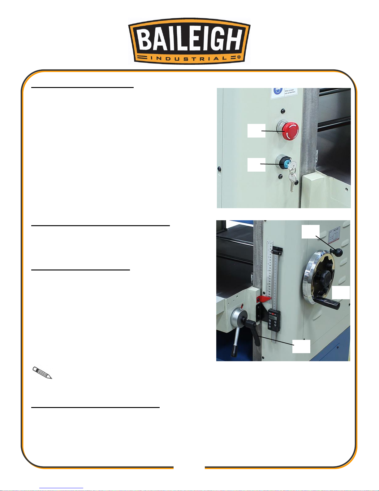
Emergency Stop (A): There are two emergency stops.
One located on the front (material in feed) left of the
planer and the other is located on the rear (material
out feed) right of the planer. Press either or both
emergency stop buttons to stop the machine. Twist the
cap 1/4 turn to release and reset the emergency stop.
Both emergency stops must be in the released
position to allow the machine to operate.
Key Switch (B): The key switch is the On/Off switch.
With power connected and the table and blade area
clear of any material or objects, to the key switch 1/4
turn clockwise
RAISING AND LOWERING TABLE
Turn the handwheel (C) clockwise to raise the table.
One revolution equals 1/16" (.0625” [1.5875mm]).
CHANGING FEED RATE
The planer has two selectable feed speeds that feed
stock at 22 and 28 feet per minute (6.7 and 8.5mpm).
To adjust speed, move lever (D) until it clicks into
place.
When the shifter knob (D), is pushed all the way in as
shown, the feed roll speed will be 28 feet per minute.
When the shifter knob is pulled all the way out, the
feed roll speed will be 22 feet per minute. When the
shifter knob is in the center (neutral) position, the feed
rolls are disengaged and the machine will stop
feeding.
Important: Change feed speed only while the feed system is RUNNING!
TABLE ROLLER ADJUSTMENT
Loosen the handle (E) and move the table rollers up, or down by raising, or lowering the handle.
When you reach the desired position tighten the handle.
The rollers are usually set higher when planing rough stock. When planing smooth stock the
table rollers should be set only slightly above, or flush with the table.
A
B
E
C
D
Page 23

20
20
CALIBRATING THE THICKNESS SCALE
The following sections will describe the use of a calibrating board. The calibrating board should
be made of a hardwood and have one side that has been run through a jointer.
1. With the planer turned "OFF - cutterhead NOT spinning", place your calibrating board jointed
surface down on the table and slide it into the machine.
2. Use the handwheel (A, Fig. 6) to raise the table so that the in-feed roller is about 1/16" above
the calibrating board.
3. Remove calibrating board from planer and turn the planer "ON".
4. Turn the handwheel clockwise one complete revolution to raise the table and run the
calibrating board through the planer.
5. Repeat Step 4 until the planer removes the entire top surface of your calibrating board.
6. Measure the thickness of the board using a pair of calipers.
7. Adjust the pointer (E, Figure 6) so that it reads the measured thickness by loosening the
screw that holds it in place.
Page 24
21
21
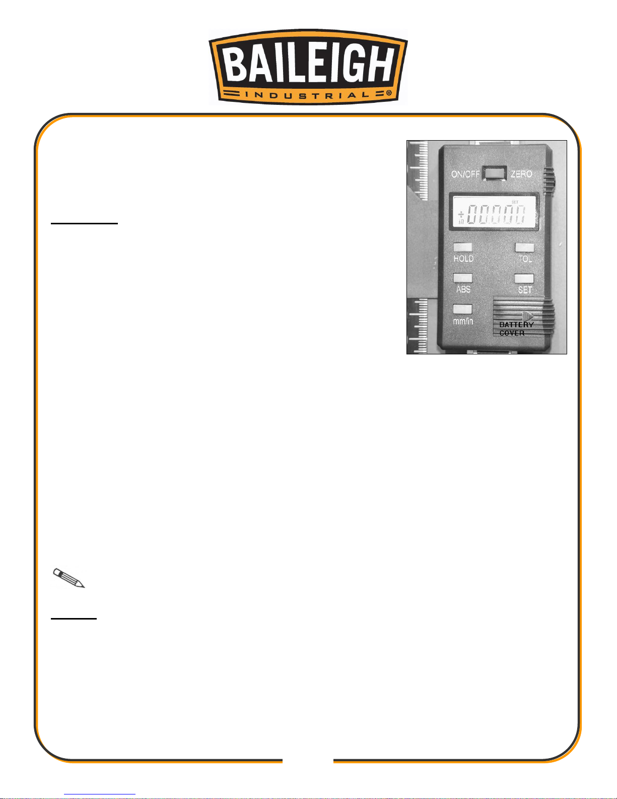
DIGITAL READOUT
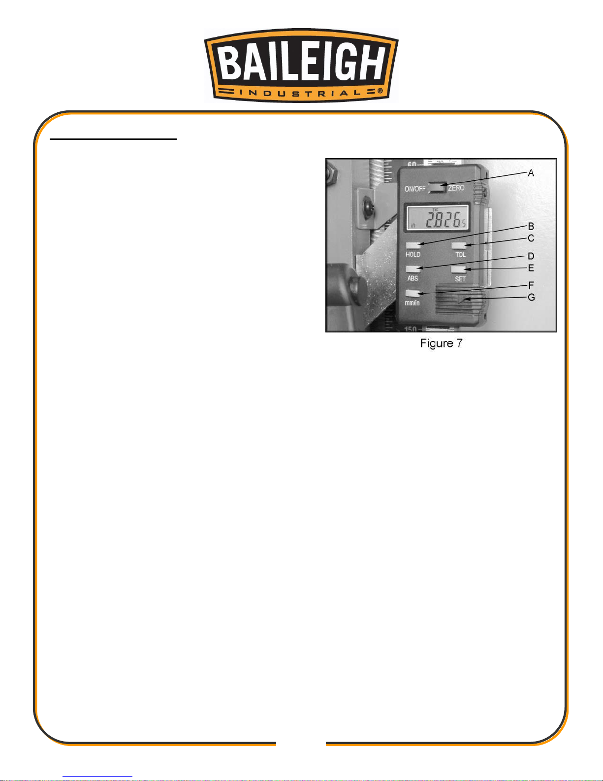
A. On/Off/Zero: Press button to turn on display.
Hold button in for a few seconds to turn off display.
When the display is on you can press button to
zero out.
B. Hold: Press hold button to lock in a reading
before the table is moved. Press the hold button
again to show current reading.
C. Tolerance: Press tolerance button once to
display beginning tolerance. Press and hold button
to toggle through display. When you reach the
position you want to change release tolerance
button and press again to make changes. Once
desired setting is made toggle to "set", displayed in
the upper right hand corner, and press tolerance
button to accept changes. Press tolerance button
again to display ending tolerance and set up as done previously. Press a third time to exit
tolerance set-up.
D. ABS: Press this button to toggle between absolute value and incremental value. When in
the incremental mode "inc" will be displayed in the upper left hand corner. incremental: When
working in the incremental mode you can zero out at any time. When you get close to your
finished thickness zero out the display and measure workpiece thickness. Use the display to
remove exact amounts from the workpiece. Absolute: When working in the absolute mode your
zero will be 0.125" to compensate for table stops. This means you will need to raise the table
completely and zero out the scale (0.125") every time after the display has been turned off or
zeroed in the absolute setting, see "Set" section below.
E. Set: Press this button to display the "zero" setting for absolute. Raise table completely.
Press and hold in set button. Make changes to zero setting by holding the button in to toggle
through display. Release set button and press again to make changes. Set the zero to 0.125".
Once the setting is made toggle to "set", displayed in the upper right hand corner, and press the
set button to accept changes. Note: This will give you an approximate reading depending on
table rollers, blade setting, etc..
F. mm/in: Press this button to toggle between metric and inches.
G. Battery Cover: Slide the cover off to replace the battery.
Page 25
22
22
The digital scale equipped with 22” planer can serve many
applications, however for wood planning we need only concern
ourselves with the ON/OFF, SET, and mm/in buttons. When set
properly the digital readout will display the thickness of the
finished product.
Calibration:
In order to calibrate the unit first run a board through the planer
and measure the finished thickness with a set of vernier calipers.
This is the number to be entered into the display unit. At this
point turn the unit on by pushing the ON/OFF button. Now press
the mm/in button to set the unit to American standard or the
metric system.
1. Press and hold the SET button until the ‘+’ sign starts to flash
and immediately release it.
2. Cycle the set button by pressing it until the ‘+’ sign remains on.
3. Press and hold the SET button until the second zero to the right of the ‘+’ plus sign starts to
flash and immediately release it.
4. Cycle the SET button by pressing it until the number reads the correct whole number taken
with the vernier calipers and immediately release the button.
5. Press and hold the SET button until the zero to the right of the decimal point starts to flash.
6. Repeat steps 4 and 5 until the last digit in the 0.001 place is entered.
7. Press and hold the SET button until the SET on the display starts to flash and immediately
release it.
8. Press and release the SET button one final time to complete the calibration.
Note: Do not turn the device off. If you do you will have to re-calibrate the unit.
Battery:
When the display begins to flash the battery should be replaced. The battery is to be replaced
with a SR144 (or equivalent) and can be found at most pharmacies or grocery stores. When
replacing the battery the positive side of the button cell must face out.
Page 26
23
23
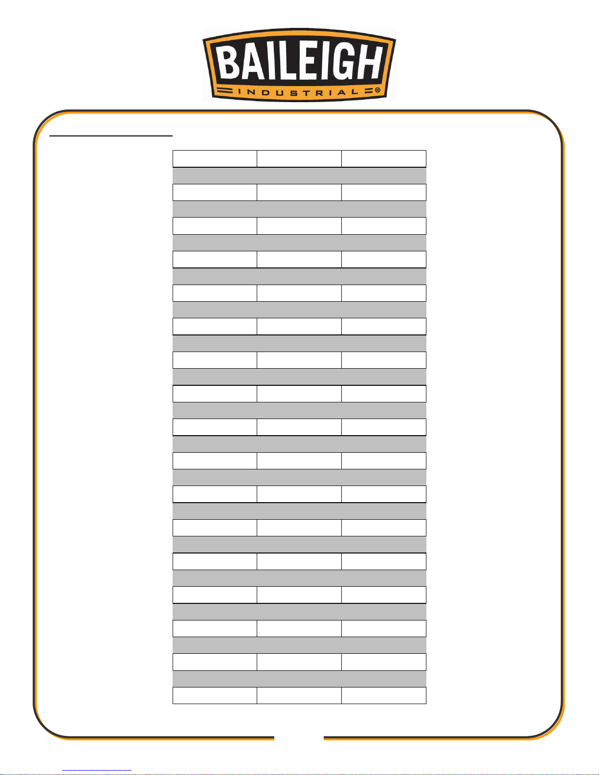
CONVERSION CHART
Fraction
Decimal
Metric
1/32
0.031
0.794
1/16
0.063
1.588
3/32
0.094
2.381
1/8
0.125
3.175
5/32
0.156
3.969
3/16
0.188
4.763
7/32
0.219
5.556
1/4
0.250
6.350
9/32
0.281
7.144
5/16
0.313
7.938
11/32
0.344
8.731
3/8
0.375
9.525
13/32
0.406
10.319
7/16
0.438
11.113
15/32
0.469
11.906
1/2
0.500
12.700
17/32
0.531
13.494
9/16
0.563
14.288
19/32
0.594
15.081
5/8
0.625
15.875
21/32
0.656
16.669
11/16
0.688
17.463
23/32
0.719
18.256
3/4
0.750
19.050
25/32
0.781
19.844
13/16
0.813
20.638
27/32
0.844
21.431
7/8
0.875
22.225
29/32
0.906
23.019
15/16
0.938
23.813
31/32
0.969
24.606
1
1.00
25.400
Page 27
24
24
SETUP OF FEED ROLLERS, CHIP BREAKER AND PRESSURE BAR
Although your planer was carefully adjusted at the factory, it should be checked before being put
into operation. Any inaccuracies due to rough handling while in transit can easily be corrected
by completing the adjustment procedures.
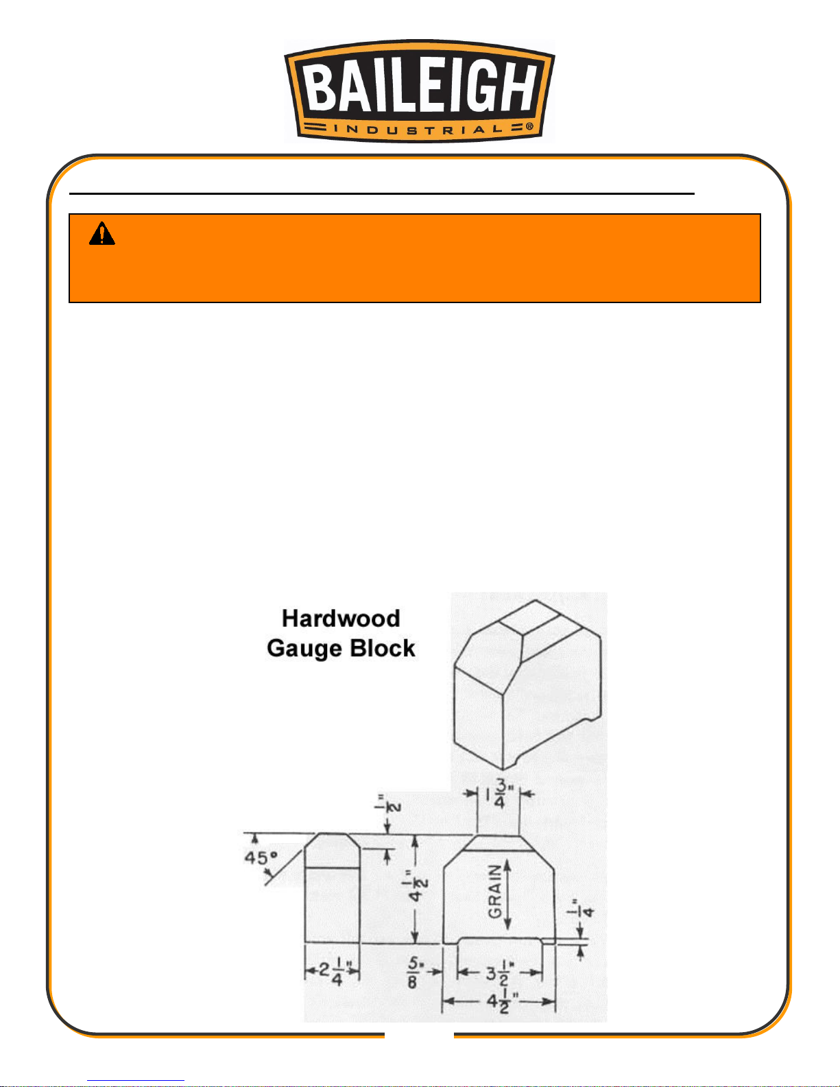
To check the adjustments, you will need a straight edge, feeler gage and a homemade gauge
block made of hardwood.
Use the diagram and dimensions to fabricate the hardwood gauge block.
The wood gauge along with a feeler gauge will be used to set the planer to the proper
dimensions.
Depending on the stock and cutterhead you may find that a different setup may work better for
your particular planning operation.
WARNING: Always disconnect and lockout power before performing any
adjustments or service work.
Blades and Anti-kickback fingers are sharp. Wear gloves to prevent injury.
Page 28
25
25
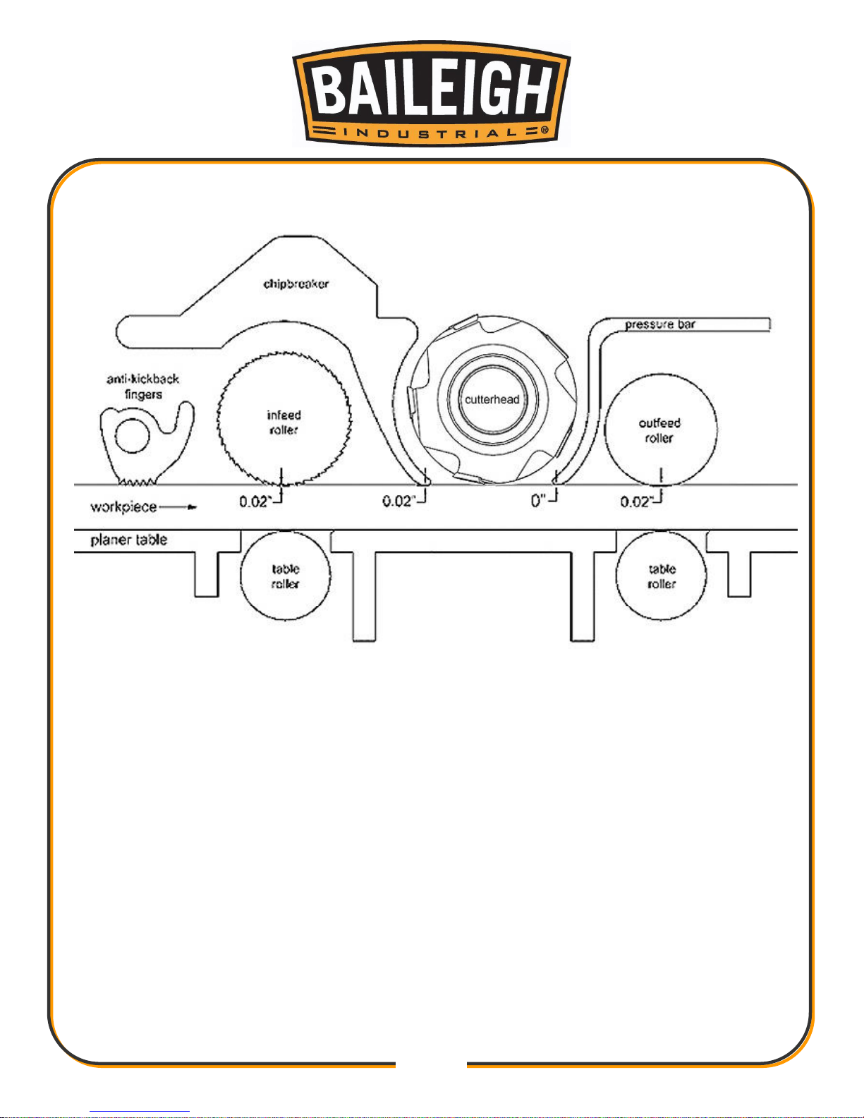
All measurements are shown below knife.
Adjustment Dimensions
Page 29
26
26
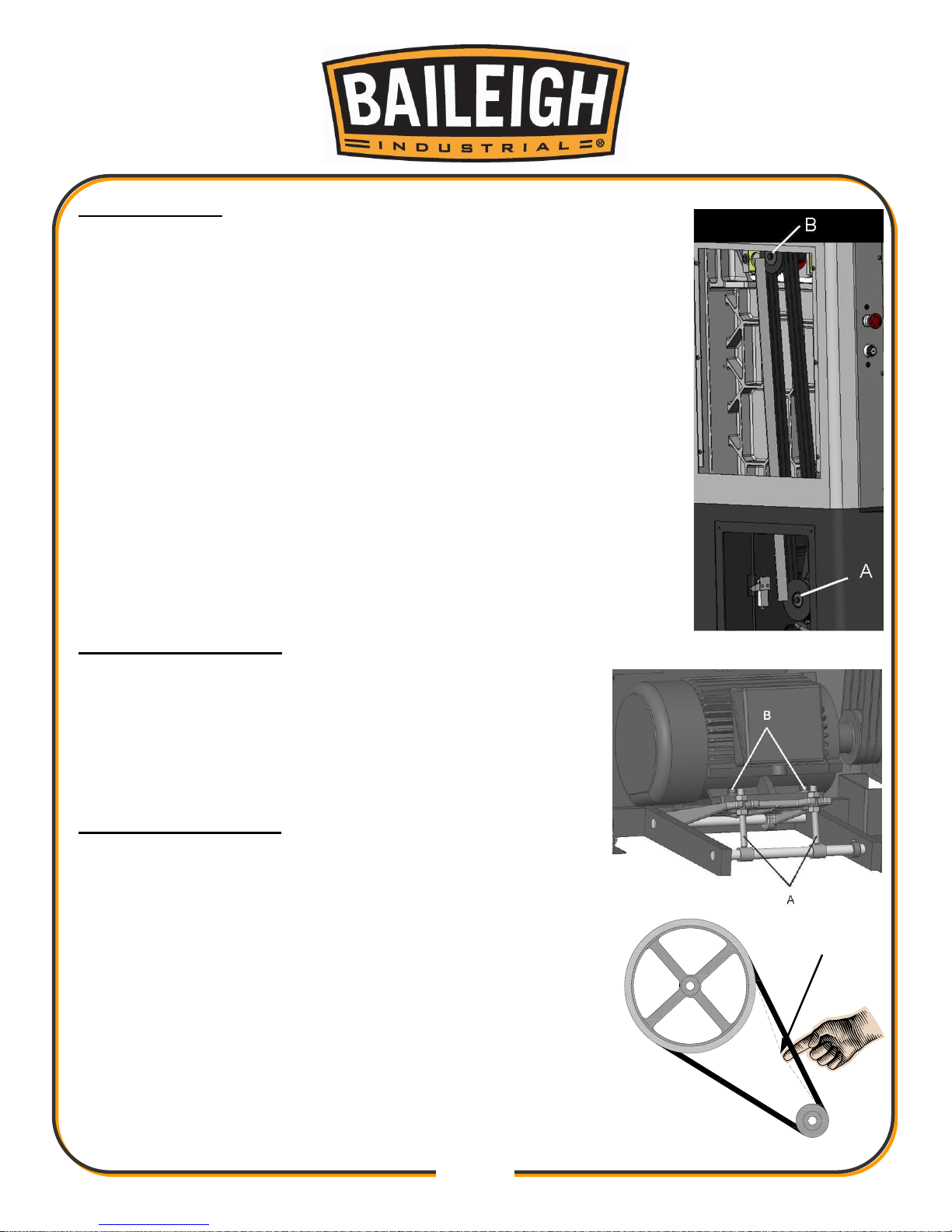
Checking Pulley
1. Make sure the pulleys are aligned to reduce side wear on the belts.
2. Place a straight edge on the edge of the motor pulley (A) and the
upper shaft pulley (B). The gap between the straight edge and the
belt should be the same from top to bottom.
Adjusting Motor Mount
1. If the motor pulley and shaft pulley are not in-line loosen
screw (B).
2. Move the motor to left and right until adjusted to proper
position and tighten the screw again.
Adjusting Belt Tension
1. Use the two jack bolts (A) to adjust the belt tension by
adjusting the upper and lower nuts to apply or remove
pressure to the belt.
2. Push the center of each belt. When properly tensioned the
amount of deflection should be approximately 0.75”
(19mm).
3. When proper belt tension is achieved, tighten the nuts to
hold the motor plate in position.
Deflection
Page 30
27
27
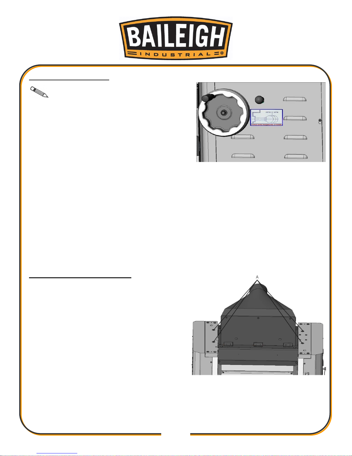
Feed Roll Speed Control
IMPORTANT: ONLY CHANGE FEED
ROLL SPEEDS WHEN THE MACHINE IS
RUNNING.
Two feed roll speeds of 28 and 22 feet per minute
are provided with your planer. Generally speaking,
the slower feed rate provides more cuts per inch,
thus a finer, smoother finish of the workpiece is
obtained. A good rule to follow would be to operate
the machine at the faster feed rate for general planing and switch to the slower feed rate for the
final finished dimension of the workpiece. When planing wide stock (wider than 8") particularly in
hard wood, the slower feed roll speed is more desirable as there is less strain on the motor and
a better finish is obtained since there are more cuts per inch of stock in length.
When the shifter knob, is pushed all the way in as shown, the feed roll speed will be 28 feet
per minute.
When the shifter knob is pulled all the way out, the feed roll speed will be 22 feet per minute.
When the shifter knob is in the center (neutral) position, the feed rolls are disengaged and
the machine will stop feeding.
Feed Roll Pressure Adjustment
The pressure of the roller will depend on the
pressure set by the spring and screws.
1. To adjust the pressure, loosen or tight the four
adjust screw and springs (A) on both ends of
the feed roller.
2. To ensure the best cutting results make sure
both side are at the same lever pressure.
Page 31
28
28
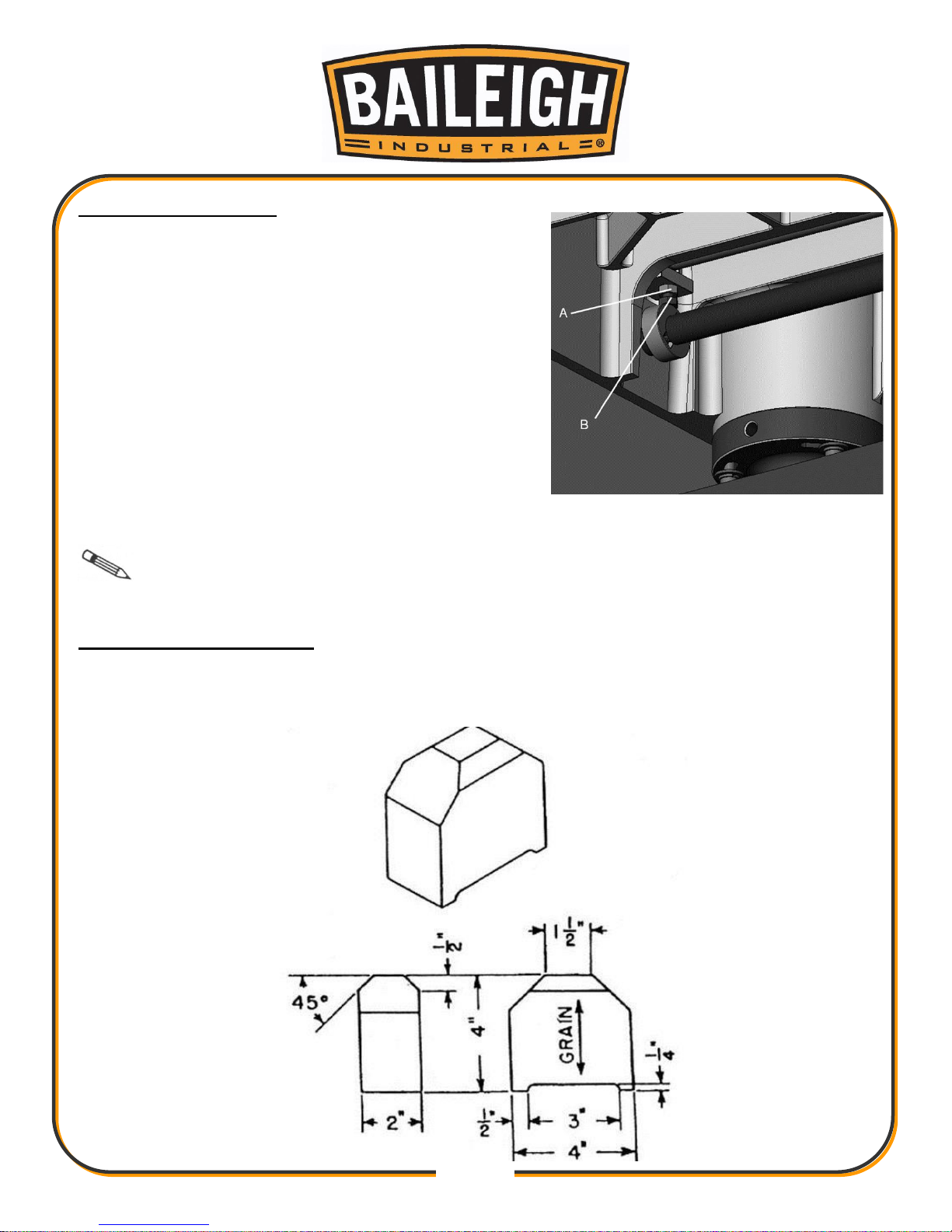
Table Roller Adjusting
To reduce friction between stock and table, two table
rollers must be assembled on machine. Adjustments
will be needed when planning with different type of
wood. The table rollers on the planer are set for
average planning and are parallel to the table surface.
1. To adjust, disconnect the machine from the power
source.
2. Place a straight edge across two rollers.
3. Loosen nut (A) and adjust screw (B) under the
table.
4. To adjusted the roller on the both sides. Used the
control lever you can let rollers upward or downward from the table.
Note: Make sure both roller are at the same level. The rollers should be set high
when planning rough wood. Rollers should be adjusted low when planning smooth wood.
Constructing Gauge Block
In order to check and adjust the height of the chipbreaker, infeed and outfeed rolls and adjust
the cutterhead parallel to the table, you will need a homemade gauge block made of hard wood.
This gauge block can be easily constructed by following the dimensions in the figure.
Page 32
29
29
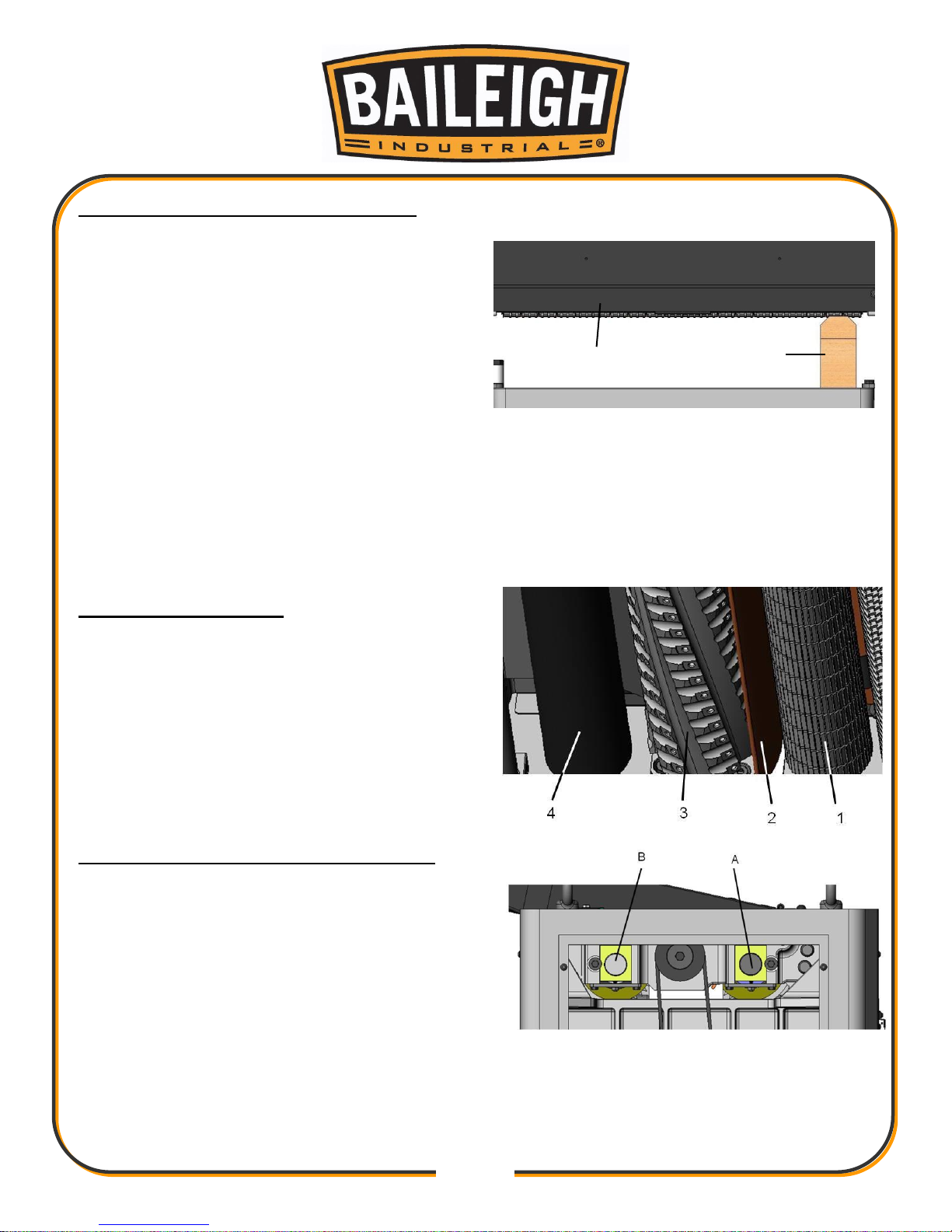
Adjusting Cutterhead Parallel to Table
The cutterhead is set parallel to the table at the
factory and no further adjustment should be
necessary. If your machine is planing a taper,
check to see if the cutterhead is set parallel to
the table as follows:
1. Disconnect machine from the power source.
2. Place the gauge block (A) on table directly
under front edge of head casting (B) as
shown.
3. Lower head casting until front edge of head casting (B) just touches the top of the gauge
block.
4. Move gauge block to the opposite side, making them to the same height.
5. Check the back side as the same step.
Cutterhead and Rollers
Infeed Roller 1
Chipbreaker 2
Cutterhead 3
Outfeed Roller 4
Adjusting Spring Tension of Feed Roller
The infeed roller (A) and the outfeed roller (B) are
two of the major parts of automatic transmitting of
planer. To control pressure, spring tension are
used.
A
B
Page 33
30
30
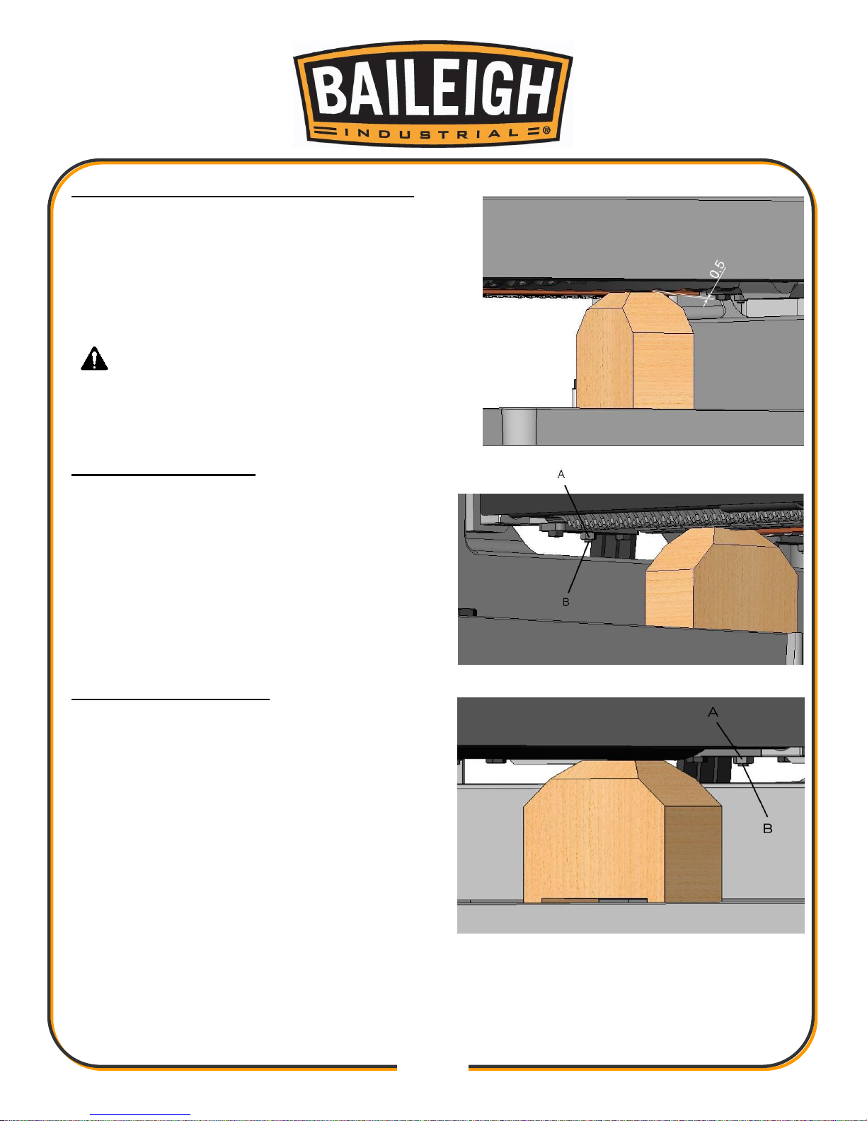
Adjusting Infeed Roller and Outfeed Roller
Before Adjust rollers, there must be made to check
position of the cutterhead used a thickness gauge
0.5mm and homemade gauge block.
Turn the handwheel to make the table upward then
place thickness gauge under the cutter, there are
must be a thickness gauge of 0.5mm to get the
correct position.
IMPORTANT: Do not move the table or
make any adjustments.
Checking Infeed Roller
Place gauge block under the infeed roller.
Loosen Nut (A) turn screw (B) that will make the
feed roller moves upward or downward. Then
making roller touch the top of gauge block. When
adjustment have been finished, tighten nut (A)
and screw (B). It is the same way to check the
height of the other end. (Fig. 15)
Checking Outfeed Roller
Place gauge block under the outfeed roller.
Loosen Nut (A) turn screw (B) that will allow for
the feed roller moves upward or downward. Then
making roller touch the top of gauge block. When
adjustment have been finished, tighten nut (A)
and screw (B). It is the same way to check the
height of the other end. (Fig. 16)
Page 34
31
31
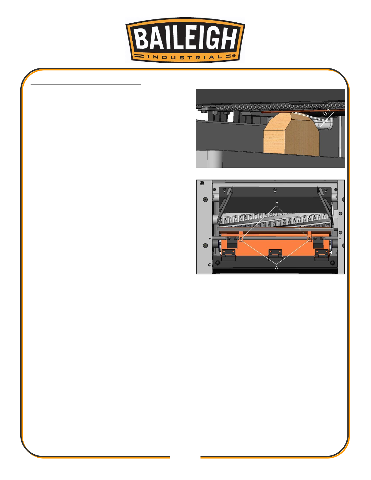
Checking Height of Chipbreaker
The chipbreaker extends down around the front
of the cutterhead and raises as stock is fed
through the planer. The chipbreaker "breaks or
curls" the chips as they leave the cutterhead and
the bottom edge of the chipbreaker helps hold the
stock flat down on the table during the planing
operation. The bottom of the chipbreaker must be
parallel to the knives and set 0.020" below the
cutting circle. To check and adjust, proceed as
follows:
1. Disconnect machine from the power source.
2. Make certain the knives are adjusted properly
as explained under "CHECKING, ADJUSTING
AND REPLACING KNIVES".
3. Place the gauge block, on the table directly
under the cutterhead as shown. Using 0.020"
feeler gauge placed on top of the gauge block,
raise or lower the head assembly until one of the
knives just touch the feeler gauge when the knife
is at its lowest point. Then lock the head
assembly in this position.
4. Place the gauge block, minus the feeler gauge,
under one end of the chipbreaker, as shown. The
bottom of the chipbreaker should just touch the top of the gauge block, as shown. (Fig. 17)
5. If the height of the chipbreaker must be adjusted, remove the top cover of the machine.
Loosen nut (A) Fig. 18, and turn screw (B) until that end of the chip-breaker is properly adjusted.
Then tighten nut (A). (Fig. 18)
Page 35
32
32
BASIC OPERATION
1. Put on safety glasses and a respirator, and secure loose clothing and long hair.
2. Unless your workpiece is very flat, surface plane the workpiece on a jointer until it is flat.
Having the face flat will ensure that it sits flat on the planer table during operation.
3. Adjust the table elevation to slightly lower than your workpiece height (approximately 1/32” –
1/16” [0.8-1.6mm]). Cuts at this depth will usually take off the high spots.
4. Start the machine by pressing the CUTTERHEAD MOTOR switch on the power/table
control.
5. Place the flat side of the workpiece down on the table, and feed the workpiece through the
planer, making sure not to stand directly in front or behind the workpiece to avoid kick-back
injury.
If the cut is too heavy and bogs down the planer:
a. Turn the planer OFF immediately by pressing the red EMERGENCY STOP button
on the power/table control.
b. Allow the planer to come to a complete stop.
c. Lower the table and remove the workpiece and repeat Steps 3–5.
6. Measure your workpiece thickness and adjust the table elevation as necessary to take a
lighter or heavier pass, depending on your needs. For most wood types, 1/8” (3.1mm) per
pass is a good cutting depth.
CAUTION: Always wear proper eye protection with side shields, face
shield, safety footwear, and leather gloves to protect from, chips, dust, burrs, and
slivers.
WARNING: DO NOT stand or allow anyone else to stand directly behind
infeed table while feeding material. DO NOT bend down to see how stock is feeding.
Should a kickback occur, serious or fatal injury could result.
Page 36

33
33
Operation Tips
Inspect lumber for defects, warping, cupping, twisting, and for foreign objects (nails, staples,
imbedded gravel, etc,). If you have any question about the quality of your lumber, do not use
it. Remember, wood stacked on a concrete floor can have small pieces of stone or concrete
pressed into the surface.
Use the full width of the planer. When feeding lumber into the planer, alternate between the
left, the right, and the middle. Your cutters will remain sharp much longer.
Scrape all glue from workpiece before planing.
Plane ONLY natural wood fiber. DO NOT plane MDF, plywood, laminates, or other synthetic
products.
Plane WITH the grain. Never feed end-cut or end-grained lumber into your planer.
Do not plane boards with loose or large knots, splits, cross grain or other obvious blemishes
or defects. These can damage the machine and pose a safety risk to the operator.
Keep your work area clear.
When planing long stock, get assistance to receive the workpiece from the outfeed table.
Avoid planing wood with high water content. Wood with more than 20% moisture content or
wood exposed to excessive moisture (such as rain or snow), will plane poorly and cause
excessive wear to the cutters and motor. Excess moisture can also hasten rust and
corrosion of the planer and/or individual components.
CUT TROUBLESHOOTING
Using a piece of semi-finished stock, set up for a 1/16” (1.59mm) deep cut with the quick-set
table roller setting at zero. Start the machine and, standing to one side of the table, begin
feeding the stock into the machine.
The infeed roller should take the material and force it under the chipbreaker and cutterhead. If
the material feeds through effortlessly, examine the finished cut carefully for imperfections.
Learning to read a board for imperfections will save hours in adjusting a planer to operate
properly.
Following are some problems that may arise and their probable remedies. The illustrations are
exaggerated for clarity.
Page 37
34
34
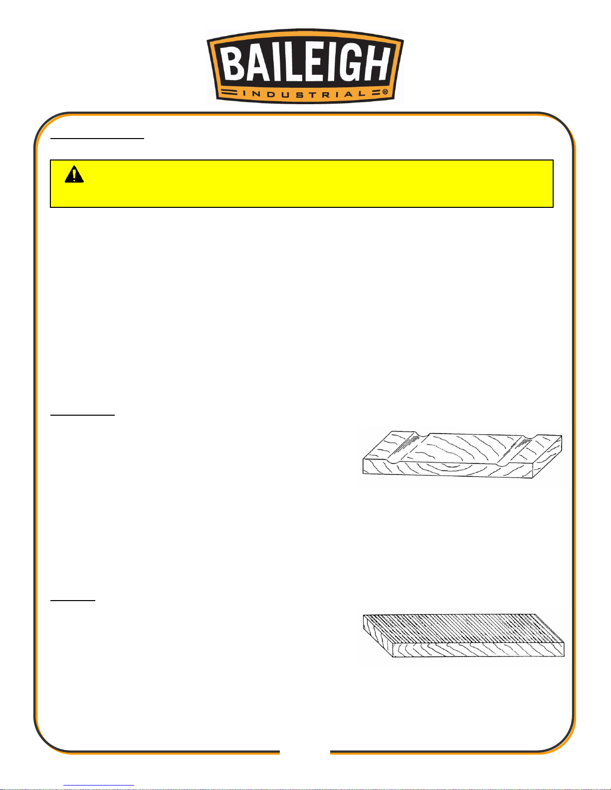
Feed Restriction
This is caused either by the table rollers being set too low for roughing operations or from a low
pressure bar. About 90 percent of the time, the pressure bar is too low. As the sharp edge of the
knife inserts wear, you must compensate for this wear by slightly raising the pressure bar an
equal amount on each side. Your first indication of knife wear is hesitation in feed of the material
through the machine after it leaves the corrugated infeed roller on its way out of the machine.
Disconnect machine from power and adjust the pressure bar accordingly. The material will free
up and feed through smoothly when the planer is restarted.
Feed restriction can also occur due to pitch buildup on the table. Be sure the table surface is
clean. Dusting the surface with talc occasionally will aid in smoother feeding and help prevent
pitch buildup.
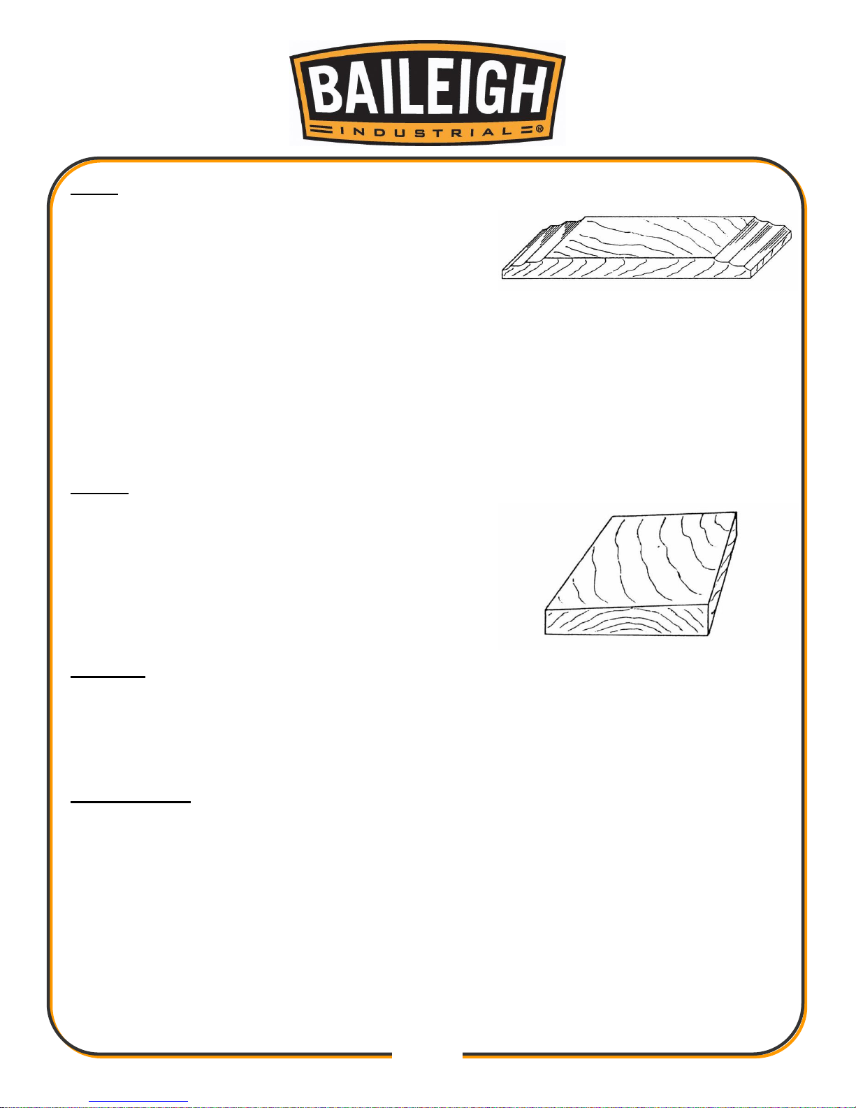
Clip Marks
If clip marks occur 6” (152mm) in from each end of the
board, the pressure bar is too high. Turn both right
and left hand adjusting screws the same amount, 1/4
turn clockwise or less, and take another 1/16” (1.59mm)
deep cut. Re-examine the board.
Continue the operate-adjust procedure until the clip marks disappear. Should the board fail to
feed through, back off slightly on both adjusting screws until feeding is smooth and the
imperfections do not re-appear. Lock the pressure bar adjusting screws with the jam nuts
provided.
Chatter
Chatter marks usually appear on thin material. Even at
their lowest point, the table rollers are too high to
handle thin material. Solve the problem by either using
a slave board or making an auxiliary table out of
Formica countertop material with cleating at each end
of the table to keep it stationary over the planer table.
CAUTION: Never attempt pressure bar adjustment while the machine is
connected to power.
Page 38
35
35
Snipe
Some amount of snipe may be inevitable with many
planer operations, but proper planer adjustments can
so minimize snipe as to make it negligible.
If noticeable snipes appear on each end of the
material, a table roller is too high causing a slight lift of the material as it passes through the
machine. Normally these snipes are more noticeable on the trailing end of the board than on
the lead end, and most often occur during planing of rough lumber.
Table rollers must be elevated for running rough or resaw lumber through the machine. When
material is turned over to surface the other side, and you neglect to lower the table rollers for
a finish cut, then definite snipes will appear on the ends of the material.
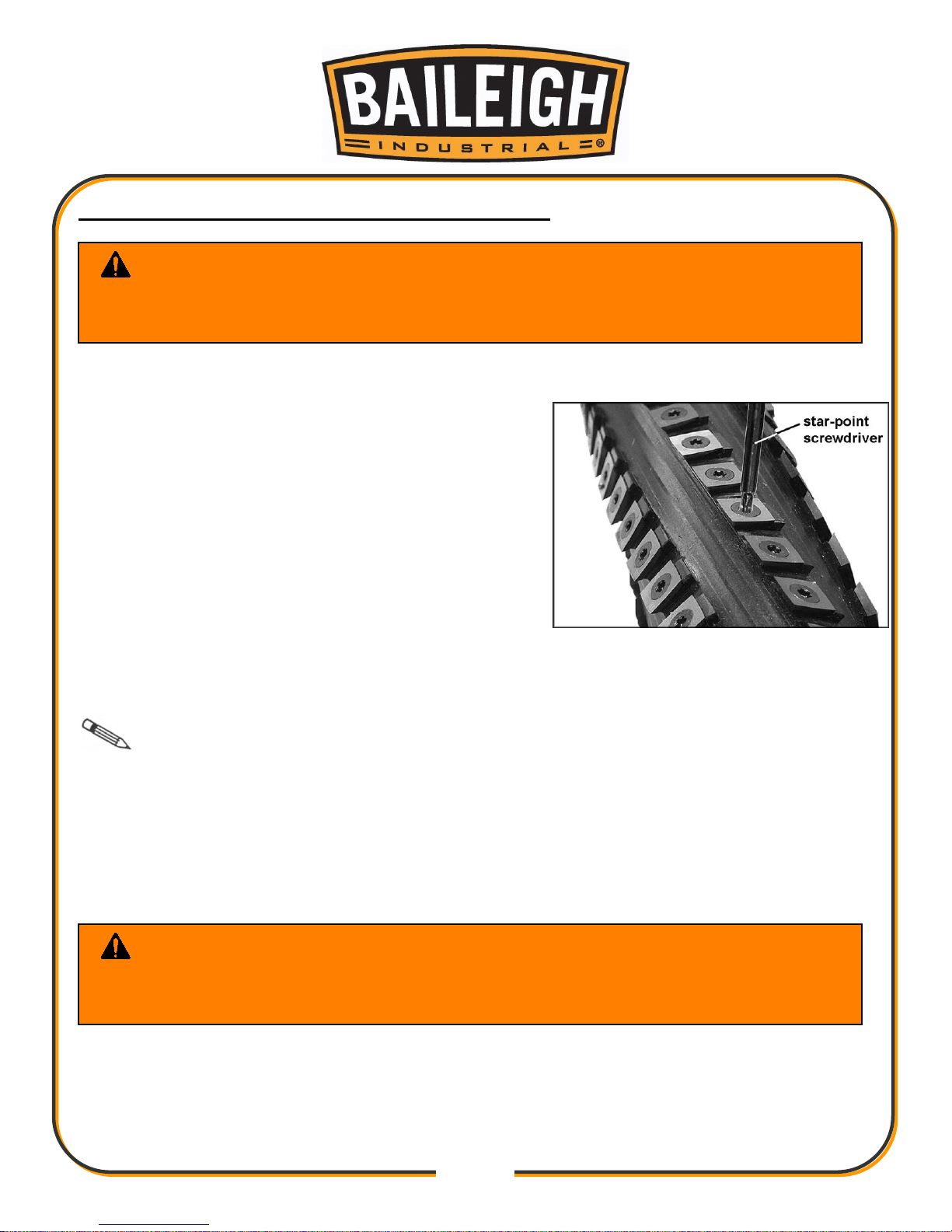
Tapers
If the machine planes a taper across the full width
of the board, the table is not parallel with the
cutterhead. First check that all knife inserts are
properly installed. If they are, then the table itself must
be adjusted. See “SETUP OF FEED ROLLERS, CHIP
BREAKER AND PRESSURE BAR”.
Twisting
If material twists while feeding through the planer, either the table rollers, pressure bar, or
outfeed roller may be out of level. See “SETUP OF FEED ROLLERS, CHIP BREAKER AND
PRESSURE BAR”.
Halted Feeding
If the in-feed roll takes stock away from you while feeding, then feeding stops before contacting
the knives, the chipbreaker is probably too low. Or the in-feed roller is not set low enough, or
does not have enough pressure. In a similar situation, the in-feed roll takes the stock, the chipbreakers lift, and stops as you hear the knives contact the material. In this case the pressure bar
is too low. See “SETUP OF FEED ROLLERS, CHIP BREAKER AND PRESSURE BAR”.
Page 39
36
36
REPLACING OR ROTATING KNIFE IN
SER
TS
The knife inserts are four-sided. When dull, simply remove each insert, rotate it 90° for a fresh
edge, and re-install.
1. Disconnect machine from power source.
2. Open the hood to access the cutterhead.
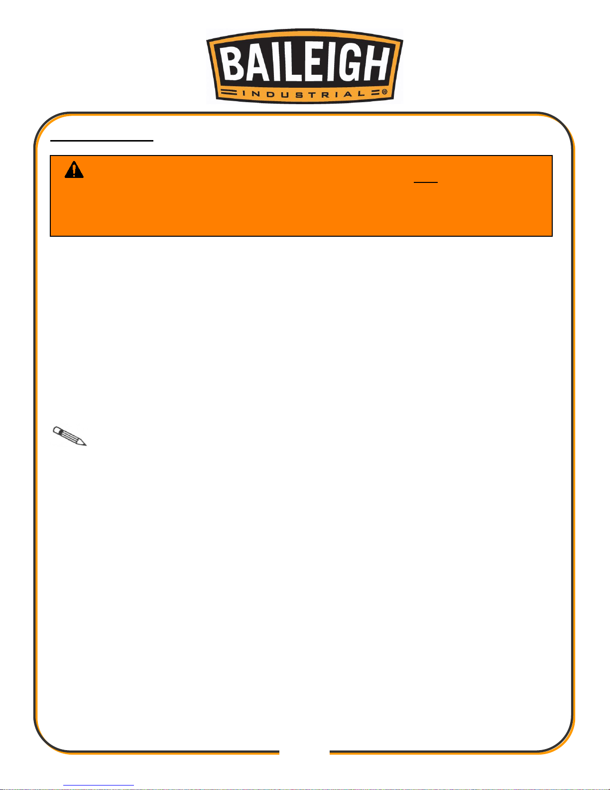
3. Use two star point screwdrivers to remove the knife
insert screw. One screwdriver can be used to help
hold the cutterhead in position while the other one is
used to remove the screw.
It is advisable to rotate all inserts at the same time
to maintain consistent cutting. However, if one or
more knife inserts develops a nick, rotate only those inserts that are affected.
Each knife insert has an etched reference mark so you can keep track of the rotations.
IMPORTANT: When removing or rotating inserts, clean saw dust from the screw,
the insert, and the cutterhead platform. Dust accumulation between these elements can prevent
the insert from seating properly, and may affect the quality of the cut.
4. Before installing each screw, lightly coat the screw threads with machine oil and wipe off any
excess.
5. Securely tighten each screw which holds the knife inserts before operating the planer.
6. Close and secure the hood before operating the planer.
WARNING: Always disconnect and lockout power before performing any
adjustments or service work.
Blades and Anti-kickback fingers are sharp. Wear gloves to prevent injury.
WARNING: Make sure all knife insert screws are tightened securely.
Loose inserts can be propelled at high speed from a rotating cutterhead, causing
injury.
Page 40
37
37
MAINTENANCE
Maintenance on your planer should be done at periodic intervals to ensure that the machine is
in good working order. Inspection and maintenance should be performed at least twice a year
but more often if the lathe receives constant use.
Check daily for any unsafe conditions and fix immediately.
Check that all nuts and bolts are properly tightened.
On a weekly basis clean the machine and the area around it.
Lubricate threaded components and sliding devices.
Apply rust inhibitive lubricant to all non-painted surfaces.
Note: Proper maintenance can increase the life expectancy of your machine.
Check all fasteners to make sure they are tight and check all adjustments that they are in
order.
Clean and oil the tables so that the material will slide easily. Clean any rust spots that may
develop on the bed with a commercial rust remover.
Use compressed air to blow out the interior of the machine in order to keep chips and
sawdust from accumulating on the belts and pulleys.
Check the drive belt for tightness. It should be snug but not overly tight.
Use a mill file to remove any nicks or dings from the infeed or outfeed tables.
Clean out-feed rollers and table with a nonflammable solvent to remove pitch, gum and
other unwanted build-up.
Keep pulleys and belts free from dirt, dust, oil and grease. Replace worn V-belts as
needed.
There are three limit switches on the planer, one that triggers if the hood is open, and a
raising and a lowering limit switch to prevent the table from automatically traveling too far.
Keep these clean and blown out with an air hose.
WARNING: Make sure the electrical disconnect is OFF before working on
the machine.
Maintenance should be performed on a regular basis by qualified personnel.
Always follow proper safety precautions when working on or around any machinery.
Page 41
38
38
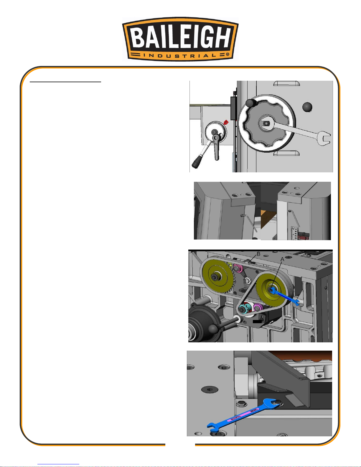
Cutter Head Removal
1. Disconnect the machine for the power source.
2. Removed Handwheel.
3. Remove right side cover and left side cover.
4. Loosen screws A. B. C and remove.
5. Remove Chip Bracket.
Page 42
39
39
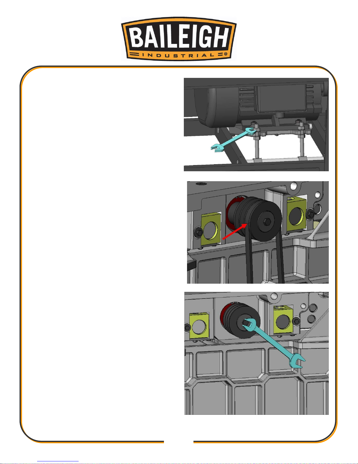
6. Loosen Nut on motor bracket.
7. Remove belt.
8. Remove cutterhead pulley.
Page 43
40
40
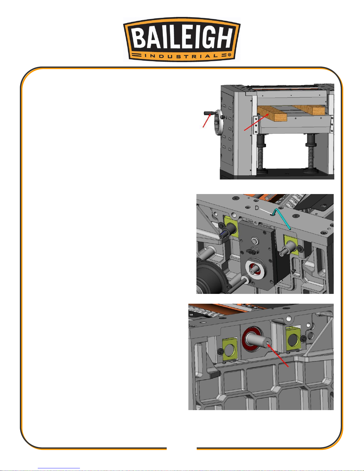
9. Place two pieces’ wood stock on table and raise
table until touch the wood stock.
10. Loosen and remove nut (D). The cutterhead &
gear box can be remove from left side.
11. Using a soft mallet, remove cutterhead.
Page 44
41
41
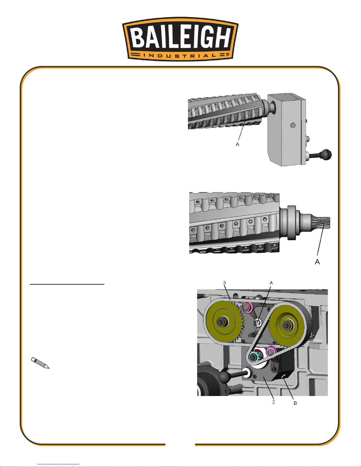
12. Remove the cutterhead & gear box from
machine.
13. Remove screw from cutterhead.
Changing Gearbox Oil
1. Disconnect the machine for the power source.
2. Loosen the nut (A) on the outfeed hole.
3. Clean out old lubrication and let it dry.
4. Tighten nut (A).
5. Replace clean lubrication by hole (B).
Note: The oil in gear box must be
change after 2500 hours of work.
Page 45
42
42
Control The depth of Cutting
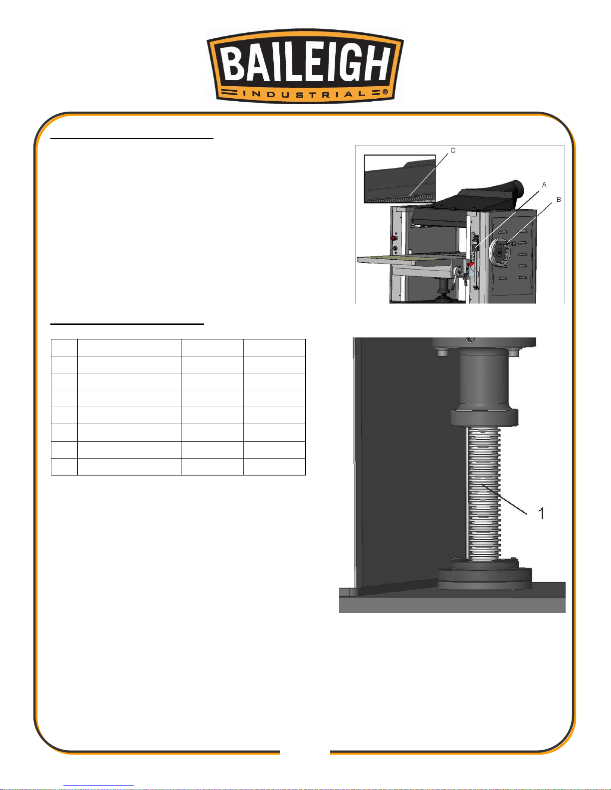
The cutting depth scale is a combination of inch/metric
scale (A). The cutting range is from 0 to 8”. The
distance between upward or downward of driving
handle (B) is 0.059” one complete turn. The maximum
depth of cut on full width planning is 1/8”. A limiter (C) is
provide to limit the depth of cut. If the workpiece to be
cut is less than 8” the allowable maximum depth of cut
no more than 1/4” in one pass.
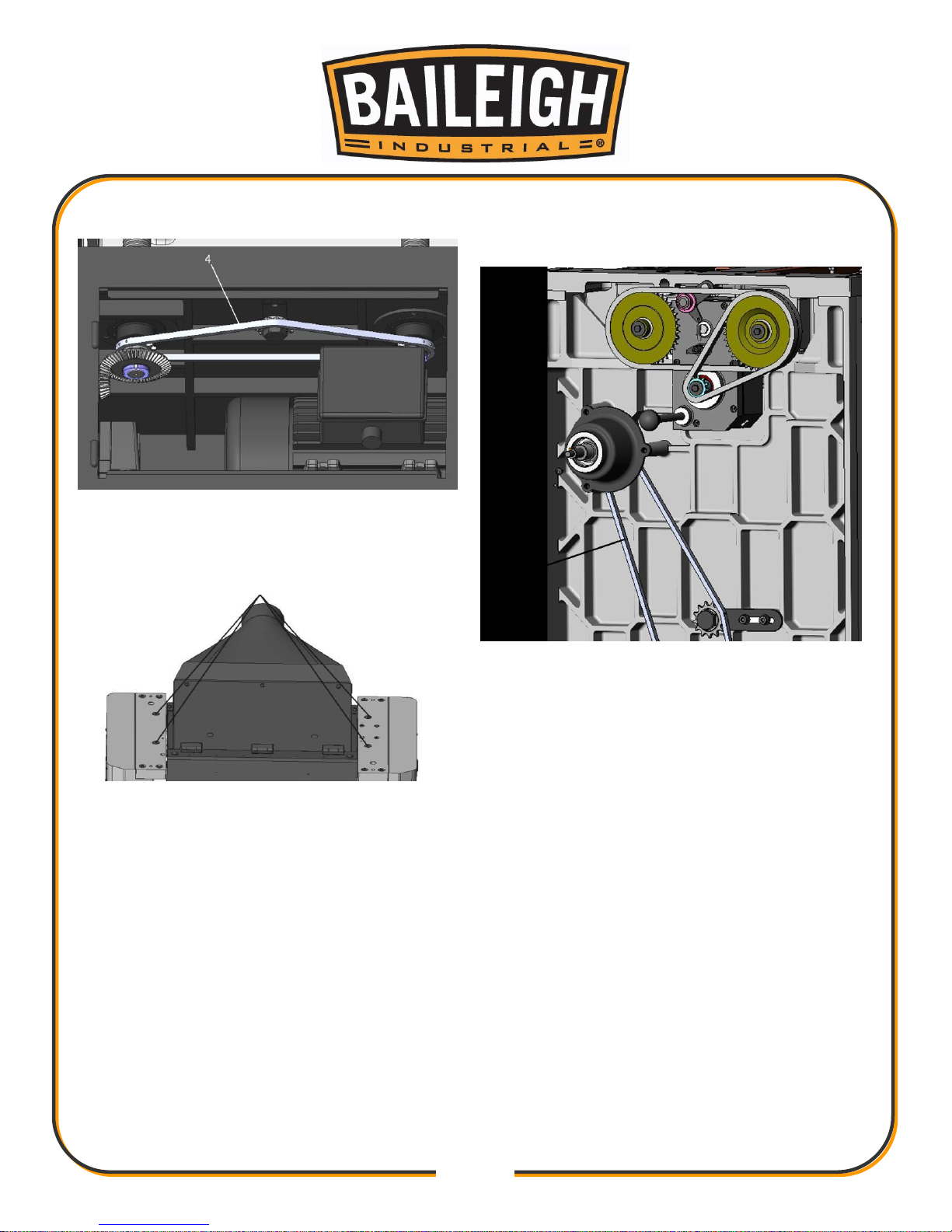
Parts Lubrication Required
No.
Descriptions
Grease
Oil
1.
Lead Screw
Yes
No
2.
Gear Box
No
Yes
3.
Chain
Yes
No
4.
Chain
Yes
No
5.
Chain
Yes
No
6.
Bracket
No
Yes
7.
Column
No
Yes
Lead Screw is used to adjust the table up or
down
All chains must be lubrication regularly.
After 30 hours or more of work the lubrication of
bracket must be added.
The machine comes equipped with four columns.
It is important to always keep them lubricated.
To ensure maximum performance always keep
the sliding rollers of table lubricated.
Page 46
43
43
Page 47
44
44
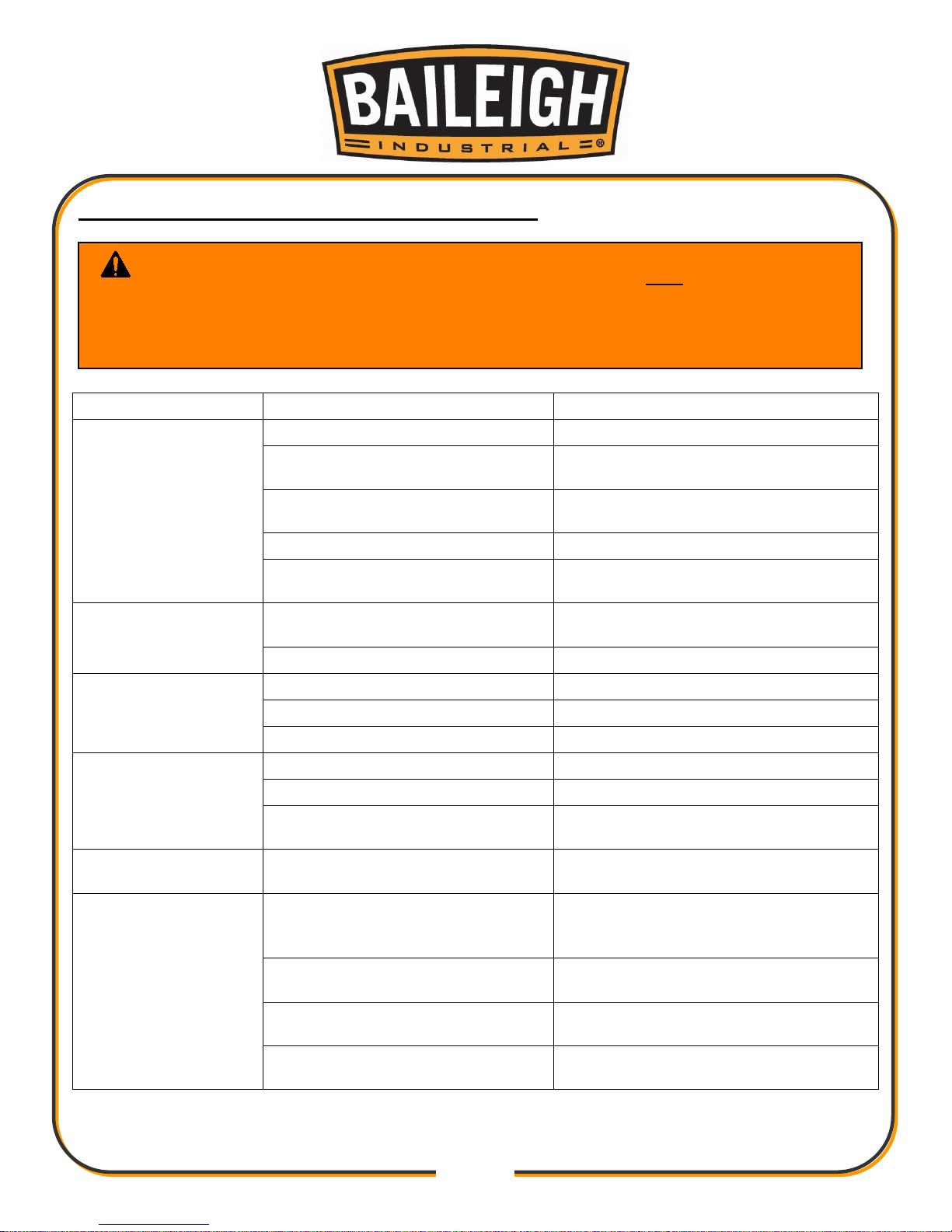
TROUBLESHOOTING: PLANER OPERATING
Trouble
Probable Cause
Remedy
Snipe.
Table rollers not set properly.
Adjust table rollers to proper height.
Inadequate support of long
boards.
Support long boards with a roller
stand.
Uneven feed roller pressure front
to back.
Adjust feed roller tension.
Dull knife inserts.
Rotate or replace knife inserts.
Lumber not butted properly.
Butt end-to-end each piece of stock
as they pass through.
Fuzzy grain.
Planing wood with a high moisture
content.
Remove high moisture content from
wood by drying, or use different stock.
Dull knife inserts.
Rotate or replace knife inserts.
Torn grain.
Too heavy a cut.
Adjust proper depth of cut.
Knife inserts cutting against grain.
Try to cut with the grain for finish cut.
Dull knife inserts.
Rotate or replace knife inserts.
Rough/raised grain.
Dull knife inserts.
Rotate or replace knife inserts.
Excessive depth of cut.
Decrease cutting depth.
Moisture content too high.
Remove high moisture content from
wood by drying, or use different stock.
Rounded, glossy
surface.
Dull knife inserts.
Rotate or replace knife inserts.
Poor feeding of
lumber.
Inadequate feed roller pressure.
Adjust feed roller tension. If proper
tension cannot be achieved, replace
feed rollers.
Planer bed rough or dirty.
Clean off pitch and residue; apply light
coat of paste wax to planer bed.
V-belts are slipping.
Check V-belt tension and make any
needed adjustments.
Surface of feed rollers has been
worn too smooth.
Lightly roughen the feed roller surface
with sandpaper.
WARNING: Make sure the electrical disconnect is OFF before working on
the machine.
Maintenance should be performed on a regular basis by qualified personnel.
Always follow proper safety precautions when working on or around any machinery.
Page 48
45
45
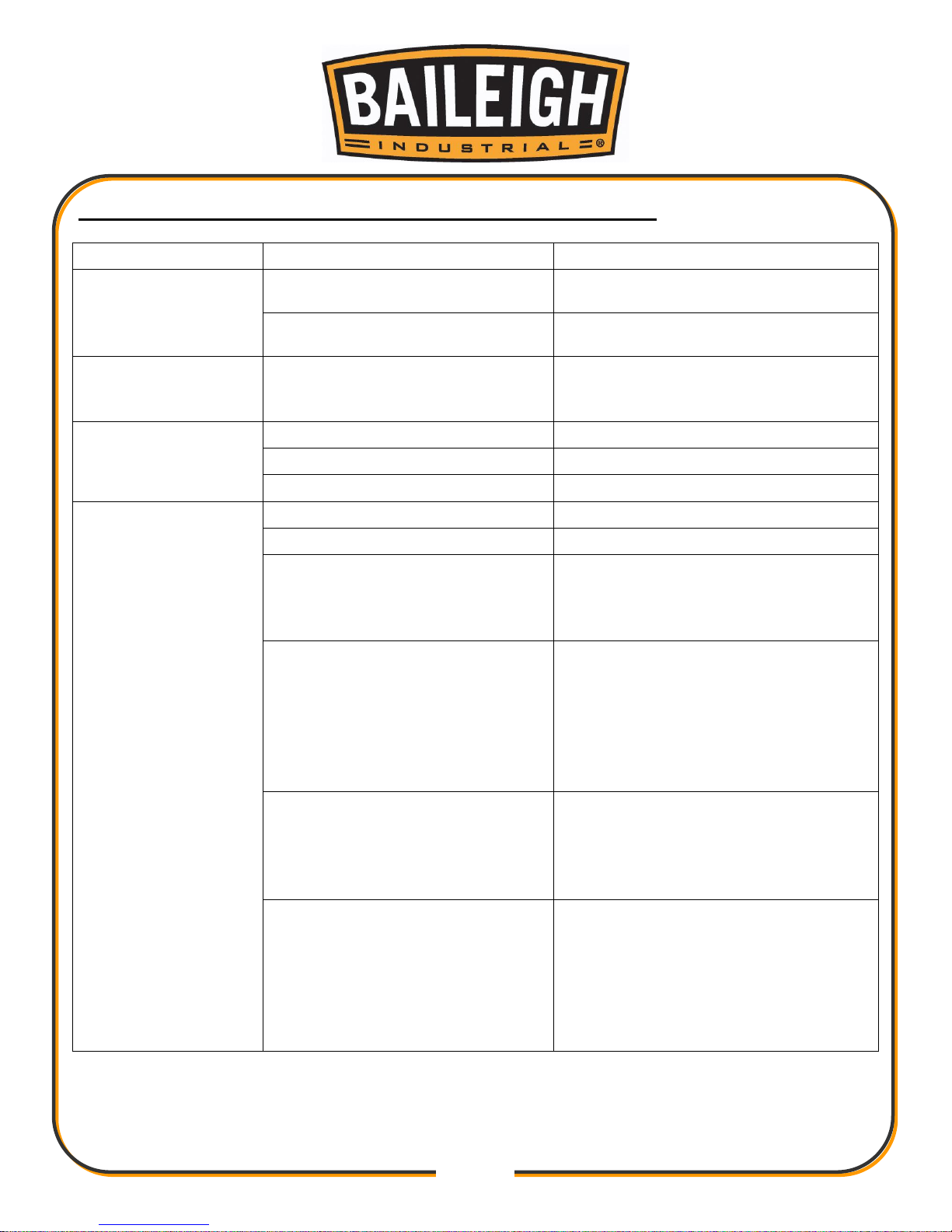
TROUBLESHOOTING: MECHANICAL AND ELECTRICAL
Trouble
Probable Cause
Remedy
Uneven depth of cut
side to side.
Knife inserts not set correctly.
Make sure knife inserts are set
correctly and securely in cutterhead.
Planer table not level with
cutterhead.
Level the table.
Board thickness does
not match depth of
cut scale.
Depth of cut scale is incorrect.
Adjust depth of cut scale. Use LED
control panel for greater precision.
Chain is jumping.
Inadequate chain tension.
Adjust chain tension.
Sprockets misaligned.
Align sprockets.
Sprockets worn.
Replace sprockets.
Machine will not
start/restart or
repeatedly trips circuit
breaker or blows
fuses.
No incoming power.
Verify machine is connected to power.
Stop button is still engaged.
Rotate stop button to disengage.
Overload automatic reset has not
reset.
Allow machine to adequately cool
before attempting restart. If problem
persists, check amp setting on the
motor starter inside the electrical box.
Planer frequently trips.
Too deep a cut. Take a lighter cut.
Check the amp setting on the
overload relay. Match the full load
amps on the motor as noted on the
motor plate.
Loose electrical lead or a failed
component.
Building circuit breaker trips or
fuse blows.
Verify that planer is on a circuit of
correct size. If circuit size is correct,
there is probably a loose electrical
lead. Check amp setting on motor
starter.
Loose electrical connections.
Go through all of the electrical
connections on the planer including
motor connections, verifying the
tightness of each. Look for any signs
of electrical arcing which is a sure
indicator of loose connections or
circuit overload.
Page 49

46
46
Trouble
Probable Cause
Remedy
Machine will not
start/restart or
repeatedly trips circuit
breaker or blows
fuses.
Motor starter failure.
Examine motor starter for burned or
failed components. If damage is
found, replace motor starter. If motor
starter looks okay but is still suspect,
you have two options: have a qualified
electrician test the motor starter for
function, or purchase a new starter
and establish if that was the problem
on change out.
If you have access to a voltmeter, you
can separate a starter failure from a
motor failure by first, verifying
incoming voltage at 220+/-20 and
second, checking the voltage between
starter and motor at 220+/-20.
If incoming voltage is incorrect, you
have a power supply problem.
If voltage between starter and motor is
incorrect, you have a starter problem.
If voltage between starter and motor is
correct, you have a motor problem.
Motor failure.
If electric motor is suspect, you have
two options: Have a qualified
electrician test the motor for function
or remove the motor and take it to a
quality electrical motor repair shop
and have it tested.
Miswiring of the machine.
Double check to confirm all electrical
connections are correct. Refer to
wiring diagram to make any needed
corrections.
Switch failure.
If a start, stop, or table movement
switch is suspect, you have two
options: Have a qualified electrical
test the switch for function, or
purchase a new switch and establish
it that was the problem on change out.
Planer does not come
up to speed.
Low current.
Contact a qualified electrician.
Page 50
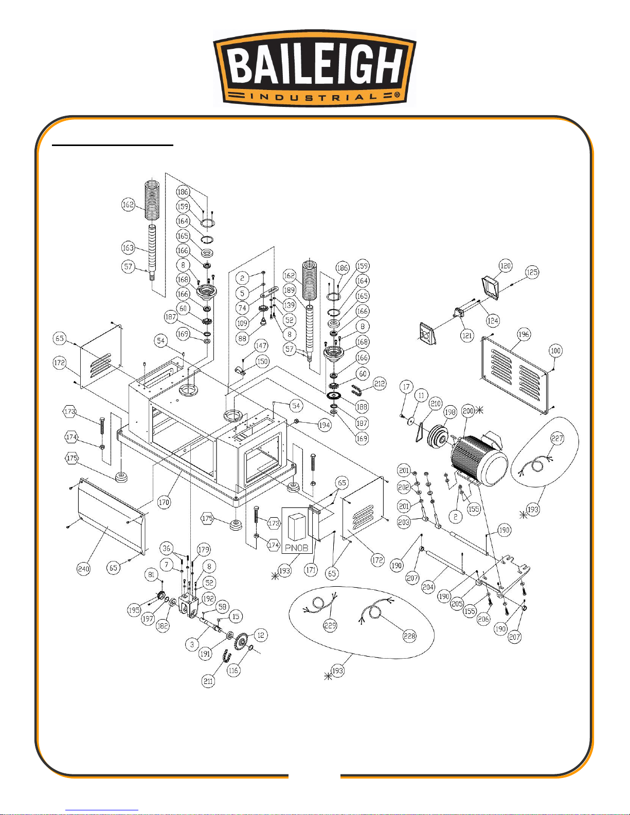
47
47
PARTS DIAGRAM
Page 51
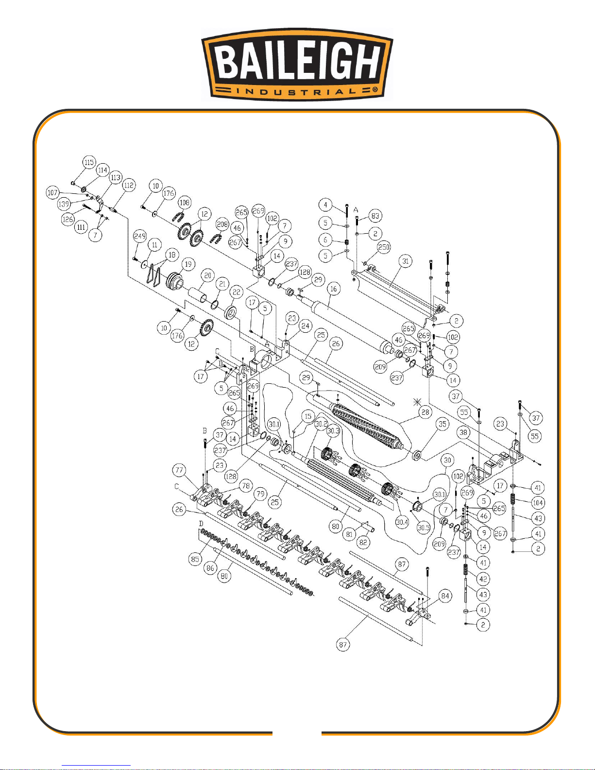
48
48
Page 52
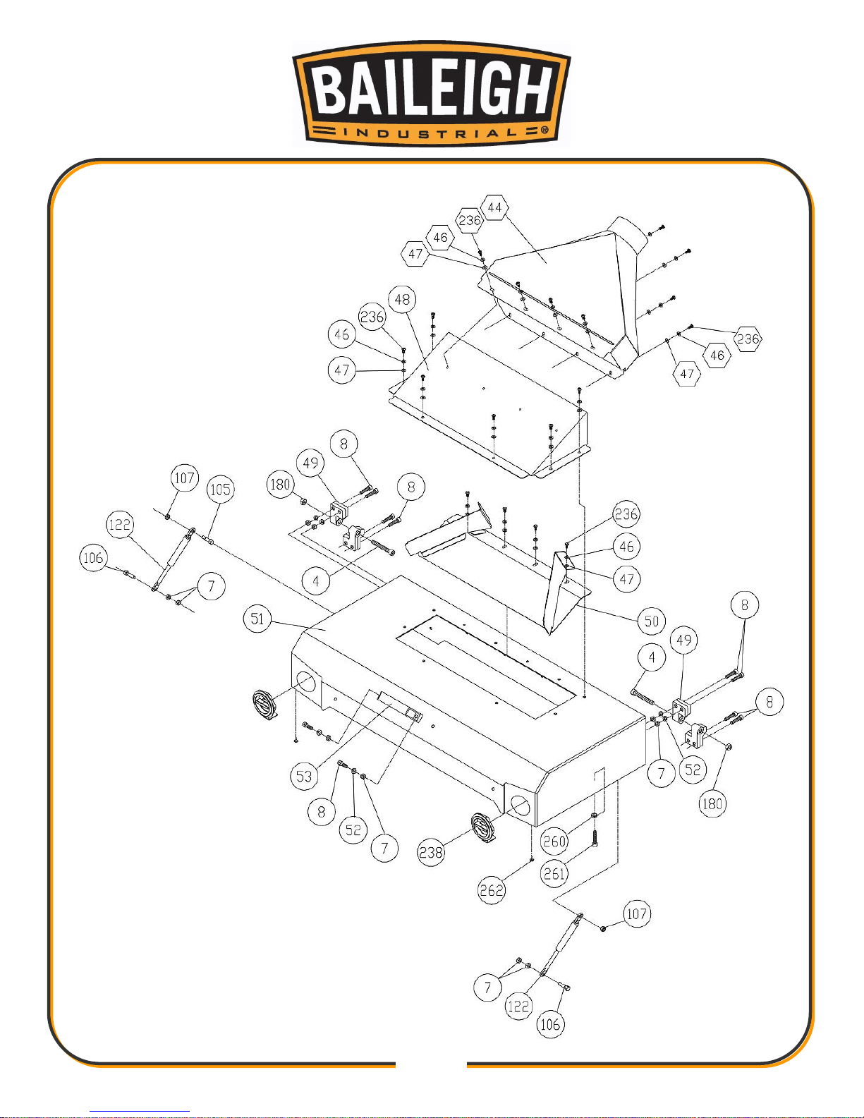
49
49
Page 53
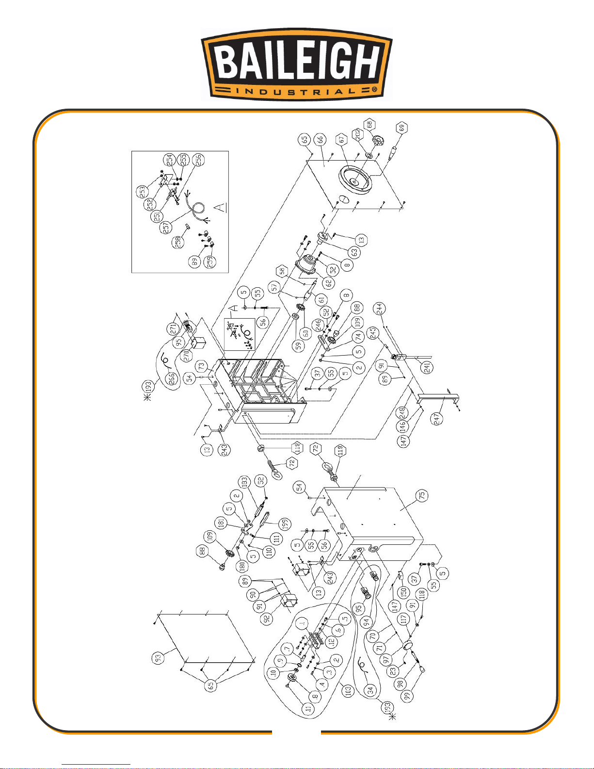
50
50
Page 54
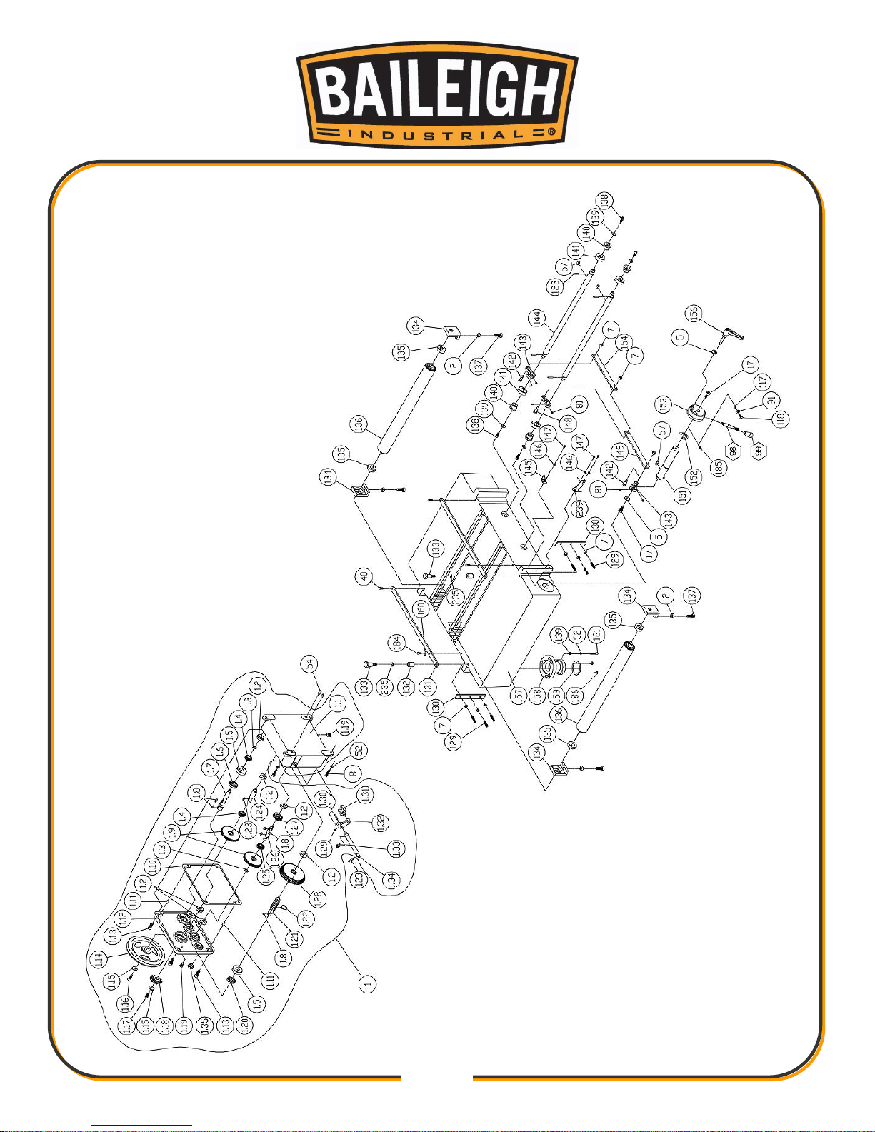
51
51
Page 55
52
52
Parts List
Item
Part No.
Description
Specification
Qty.
1
920314-000
Gearbox Assembly
1
1.01
050322-008
Gear Box
1
1.02
030205-002
Ball Bearing
6201
6
1.03
010007-000
S-Ring
STW-16
2
1.04
320208-000
Gear 20t
2
1.05
030208-002
Ball Bearing
6204
2
1.06
043605-000
Oil Seal
TC24*40*7
1
1.07
360430-000
Shaft
1
1.08
012003-002
Key
5*5*10
4
1.09
320209-000
Gear 60t
2
1.10
340029-000
Oil Seal
235*216*2t
1
1.11
360413-901
Pin
2
1.12
050323-008
Gear Over
1
1.13
000105-102
Socket Head Cap Screw
M10*1.5P*25
4
1.14
050324-902
Gear Pulley
1
1.15
006001-071
Flat Washer
10*25*3.0t
2
1.16
000105-101
Socket Head Cap Screw
M10*1.5P*20
1
1.17
001301-101
Cap Screw-Left Cap
M8*1.25P*20
1
1.18
320310-902
Sprocket
1
1.19
043401-000
Oil Plug
PT1/4"-19
2
1.20
043603-000
Oil Seal
TC20*40*7
1
1.21
360431-000
Shaft
1
1.22
010011-000
S-Ring
STW-25
1
1.23
012003-005
Key
5*5*16
2
1.24
360432-000
Gear Shaft (A)
1
1.25
320210-000
Gear 18t
1
1.26
360433-000
Gear Shaft (B)
1
1.27
320211-000
Gear 24t
1
1.28
320051-000
Gear
1
1.29
000202-101
Set Screw
M5*0.8P*5
1
1.30
011002-106
Spring Pin
4*25
1
1.31
070018-000
Transmission Jaw
1
1.32
050216-000
Speed Arm
1
Page 56
53
53
Item
Part No.
Description
Specification
Qty.
1.33
010208-000
E-Ring
ETW-12
1
1.34
360434-902
Shaft
1
1.35
043001-000
Oil Level Sight Glass
29 1 2
008007-100
Hex Nut
M10*1.5P(17B*8H)
23
3
360424-000
Bevel Gear Shaft
1
4
000105-109
Socket Head Cap Screw
M10*1.5P*75
4 5 006001-071
Flat Washer
10*25*3.0t
32 6 280056-901
Spring
2 7 008006-100
Hex Nut
M8*1.25P(13B*6.5H)
28 8 000104-108
Socket Head Cap Screw
M8*1.25P*25
30
9
173879-902
Plate
4
10
001302-101
Cap Screw-Left Cap
M10*1.5P*20
2
11
006001-084
Flat Washer
11*53*3.0t
2
12
070017-902
Sprocket
4
13
000103-106
Socket Head Cap Screw
M6*1.0P*16
12
14
051267-902
Bearing Housing
4
15
012005-001
Key
8*7*18
2
16
360411-000
Rear Outfeed Roller
1
17
000105-101
Socket Head Cap Screw
M10*1.5P*20
9
18
014111-000
V-Belt
A80
2
19
050565-902
Machine Pulley
1
20
190024-902
Bushing
1
21
010111-000
R-Ring
RTW-85
1
22
030218-002
Ball Bearing
6209
1
23
000204-102
Set Screw
M8*1.25P*10
9
24
050304-000
Left Cutterhead Bracket
1
25
360409-902
Cutterhead Shaft
2
26
360418-902
Shaft
2
28
924405-000
Helical Head Assembly
1
28A
038201-702
Inner Star Screw
#10-32UNF*12.5
125
28B
210114-000
Insert Blades
15*15*2.5t
125
28.2
850586-000
Replacement Blade Parts Kit
1
040703-000
T-Type Star Plate Hand
T-25
2
038201-702
Dish Inner Star Screw - Set
#10-32UNF * 12.5
10
210114-000
Insert Blade - Set
15 * 15 * 2.5t
10
Page 57
54
54
Item
Part No.
Description
Specification
Qty.
29
012005-002
Key
8*7*30
2
30
920371-000
Front Roller Assembly
1
30.1
130157-903
Front Roller Spacer Ring
2
30.2
360621-000
Front Roller Fixed Shaft
1
30.3
130052-903
Front Roller
22
30.4
250352-615
Rubber Pin
132
30.5
000204-102
Set Screw
M8*1.25P*10
4
31
050308-000
Rear Press Plate
1
32
041503-018
Plastic Sheet
720*570*0.05t
2
33
041502-009
Plastic Sheet
1800*1300*0.1t
1
35
030202-002
Ball Bearing
6007
1
34
471003-001
Cable
14AWG*1C*250mm
1
36
000204-105
Set Screw
M8*1.25P*20
2
37
000105-104
Socket Head Cap Screw
M10*1.5P*35
20
38
050303-000
Right Cutterhead Bracket
1
40
000003-102
Hex Screw
M8*1.25P*16
2
41
170512-901
Fix Washer
8
42
280055-901
Spring
2
43
360408-902
Shaft
4
44
174338-000
Collector Hood
1
45
945863-000
Nameplate
Baileigh(CSA)
1
46
006303-100
Spring Washer
6.1*12.3
18
47
006001-032
Flat Washer
6.6*13*1.0t
10
48
170508-000
Pulley Cover
1
49
050320-000
Holder Cover
4
50
920316-000
Lead Plate Assembly
1
51
170876-000
Top Cover
1
52
006305-100
Spring Washer
8.2*15.4
27
53
250123-615
Handle
1
54
360413-901
Pin
10
55
006307-100
Spring Washer
10.2*18.5
20
56
000105-105
Socket Head Cap Screw
M10*1.5P*40
2
57
012003-002
Key
5*5*10
7
58
012003-005
Key
5*5*16
1
59
030103-002
Ball Bearing
6004
1
Page 58
55
55
Item
Part No.
Description
Specification
Qty.
60
380259-000
Sprocket
3
61
360425-901
Handle Wheel Shaft
1
62
050311-902
Handle Wheel Bracket
1
63
050174-000
Handle Wheel Seat
1
65
000801-101
Socket Head Button Screw
M6*1.0P*10
28
66
170502-000
Right Side Plate
1
67
240032-008
Hand Wheel
1
70
017002-000
Steel Ball
6 1 71
280018-000
Spring
1
72
000601-103
Lifting Eye
M20*2.5P*50
2
73
051367-000
Right Column
1
74
170413-901
Bracket
2
75
050352-000
Left Column
1
77
050307-000
Left Press Plate Seat
1
78
050305-000
Front Press Plate
10
79
280053-000
Turn Spring
10
80
360410-902
Shaft
2
81
000202-101
Set Screw
M5*0.8P*5
9
82
190025-902
Limiting Shaft
1
83
000105-107
Socket Head Cap Screw
M10*1.5P*50
2
84
050306-000
Right Press Plate Seat
1
85
250160-615
Spacer
72
86
172281-905
Anti-Kick Finger
62
87
360416-902
Shaft
2
88
290040-901
Idler Shaft
3
89
000302-103
Round Head Screw
M4*0.7P*10
4
90
006301-100
Spring Washer
4.1*7.7
4
91
006001-001
Flat Washer
4.3*10*1.0t
6
92
250168-615
Switch Box
2
93
170503-000
Lift Side Plate
1
94
490010-000
Start Switch
1
95
490039-000
Stop Switch
1
97
380151-910
Shaft
1
98
360414-910
Handle Shaft
1
99
250054-615
Handle
1
Page 59
56
56
Item
Part No.
Description
Specification
Qty.
100
000403-204
Flat Head Screw
M6*1.0P*20
4
102
000204-106
Set Screw
M8*1.25P*25
4
103
921346-000
Idle Belt Assembly
1
103.1
171789-901
Idler Shaft
1
103.2
006001-053
Flat Washer
8.5*19*2.0t
4
103.3
006305-100
Spring Washer
8.2*15.4
4
103.4
000104-104
Socket Head Cap Screw
M8*1.25P*16
4
103.5
000105-101
Socket Head Cap Screw
M10*1.5P*20
1
103.6
006307-100
Spring Washer
10.2*18.5
1
103.7
360678-901
Shaft
1
103.8
380458-902
Idle Belt
1
103.9
010101-000
R-Ring
RTW-30
1
103.10
030105-002
Ball Bearing
6200
1
103.11
000803-103
Socket Head Button Screw
M10*1.5P*20
1
103.12
006001-078
Flat Washer
10.5*19*1.5t
1
104
280054-901
Rear Outfeed Roller Spring
2
105
290024-901
Screw
2
106
290025-901
Screw
2
107
008306-100
Lock Nut
M8*1.25P(13B*9H)
3
108
016007-000
Chain
#40*72P
1
109
150001-000
Idler
3
110
010204-000
E-Ring
ETW-7
1
111
280069-000
Spring
2
112
380141-902
Idler Shaft
1
113
170183-901
Idler Shaft
1
114
360729-000
Tension Wheel
1
115
360349-901
Pulley Shaft
1
116
010011-000
S-Ring
STW-25
1
117
170014-156
Pointer
2
118
000302-102
Round Head Screw
M4*0.7P*8
2
119
008012-100
Hex Nut
M20*2.5P(30B*16H)
2
120
920317-000
Terminal Cover
1
120.1
490124-008
Junction Box Cover
1
120.2
490125-008
Junction Box
1
121
920318-000
Terminal Plate
1
Page 60
57
57
Item
Part No.
Description
Specification
Qty.
122
660017-000
Cylinder
2
123
011003-104
Spring Pin
5*25
5
124
000303-207
Round Head Screw
M5*0.8P*20
2
125
003303-102
Round Head Screw
3/16"-24NC*1/4"
1
126
000104-114
Socket Head Cap Screw
M8*1.25P*50
1
128
010501-000
Retainer Ring
ISTW-30
4
129
000204-108
Set Screw
M8*1.25P*35
6
130
170498-901
Plate
2
131
170511-902
Lead Plate
2
132
190002-905
Position Point
2
133
290009-902
Shoulder Screw
2
134
130049-903
Roller Bracket
4
135
030108-002
Ball Bearing
6203
4
136
920319-000
Roller Assembly
2
136.1
190027-906
Roller
1
136.2
361233-000
Roller Shaft
2
137
000004-103
Hex Screw
M10*1.5P*30
4
138
000104-104
Socket Head Cap Screw
M8*1.25P*16
4
139
006001-053
Flat Washer
8.5*19*2.0t
13
140
360419-901
Shaft
4
141
130050-000
Up/Down Cam
4
142
290016-901
Special Screw
2
143
130048-903
Connect Plate
3
144
360421-901
Shaft
2
145
170509-156
Pointer
1
146
006001-012
Flat Washer
5.3*12*1.0t
1
147
000303-103
Round Head Screw
M5*0.8P*10
8
148
290015-901
Special Screw
1
149
170500-901
Rod Plate
1
150
021103-000
Wire Holder
ACC-3
8
151
360420-902
Shaft
1
152
010211-000
E-Ring
ETW-24
1
153
050313-902
Rod Seat
1
154
170499-901
Rod Plate
1
155
006001-075
Flat Washer
10.3*22*2.0t
8
Page 61
58
58
Item
Part No.
Description
Specification
Qty.
156
230122-000
Universal Handle
1
157
050315-000
Middle Table
1
158
050318-902
Bolt Shaft
2
159
170481-901
Collar
4
160
006001-027
Flat Washer
6.5*16*0.8t
2
161
000104-112
Socket Head Cap Screw
M8*1.25P*40
6
162
250173-615
Expansion Bend
2
163
360423-000
Lock Bolt
1
164
010110-000
R-Ring
RTW-68
2
165
030203-002
Ball Bearing
6008
2
166
031003-001
Bearing
51105
4
168
050319-902
Bushing Bracket
2
169
008201-100
Bushing Nut
M25*1.5P
2
170
170877-000
Base
1
171
170495-008
Electromagnetic Switch
Mounting Plate
1
172
170505-000
Base Side Cover
2
175
050314-008
Foot
4
176
006001-083
Flat Washer
11*37*3.0t
2
179
000204-107
Set Screw
M8*1.25P*30
1
180
008308-100
Lock Nut
M10*1.5P(17B*12H)
3
181
170501-904
Idler Shaft
1
182
030109-002
Ball Bearing
6204
1
183
380137-902
Idler Shaft
1
184
000002-103
Hex Screw
M6*1.0P*16
2
185
000203-104
Set Screw
M6*1.0P*12
1
186
001601-101
Screw With Washer
M4*0.7P*8/4*10*0.8t
8
187
006802-100
Washer
25 2 188
320206-000
Bevel Gear (50t)
1
189
360634-000
Lock Bolt
1
190
000204-103
Set Screw
M8*1.25P*12
7
191
030104-002
Ball Bearing
6005
1
192
050312-902
Bevel Gear Bracket
1
193
937876-000
Magnetic Switch Assembly
10HP*220220V*60HZ*3PH*CSA
1
Page 62
59
59
Item
Part No.
Description
Specification
Qty.
194
021503-000
Wire Protection Ring
15.5*19*5.5
1
195
320207-000
Bevel Gear (25t)
1
196
170479-000
Stand Access Panel
1
197
010010-000
S-Ring
STW-20
1
198
050309-902
Motor Pulley
1
199
380138-902
Spring Shaft
1
200
901071-000
Motor Assembly
10HP*220V*60HZ*3PH*2P
1
201
008009-100
Hex Nut
M12*1.75P(19B*10H)
4
202
006002-091
Flat Washer
13*28*3.0t
8
203
380249-901
Adjustment Rod
2
204
360394-000
Shaft
2
205
050321-008
Motor Plate
1
206
000004-105
Hex Screw
M10*1.5P*40
4
207
190074-901
Spacer
2
208
016008-000
Chain
#40*60P
1
209
032101-002
Needle Bearing
NA-6906
4
210
014105-000
V-Belt
A56
1
211
016013-000
Chain
#40*107P
1
212
016003-000
Chain
#40*80P
1
*213
940699-000
Manual
1
226
042005-000
Desiccant
100g
1
227
474005-002
Cable
SJT10AWG*4C*950mm
1
228
474005-005
Cable
SJT10AWG*4C*550mm
1
229
474003-013
Cable
SJT14AWG*4C*2350mm
1
235
010205-000
E-Ring
ETW-8
2
236
002501-101
Button Head Locking Screw
M6*1.0P*10L
10
237
010107-000
R-Ring
RTW-47
4
238
920664-000
Knob Set
2
170903-902
Blanks
1
230167-615
Nylon Nut
P-LG-M63-B
1
000304-102
Round Head Screw
M6*1.0P*10
1
006001-022
Flat Washer
6.3*13*1.0t
1
239
170879-904
Slide Bracket
1
240
170878-000
Base Front Cover
1
241
660019-000
9" DRO Digital R/O
9 inch
1
Page 63
60
60
Item
Part No.
Description
Specification
Qty.
243
270025-902
Spring Plate
2
244
000404-101
Flat Head Screw
M3*0.5P*6
2
245
006001-003
Flat Washer
4.3*12*1.0t
1
246
006001-049
Flat Washer
8.5*16*2.0t
2
247
170881-000
9" DRO Digital R/O Cover
1
248
230274-000
Hex Bolt
2
249
002604-101
Socket Head Cap Screw
M10*1.5P*20
1
250
006712-100
Wavy Washer
BWW-6001
1
251
490018-000
Micro Switch
125V*20.5AMP
1
252
170680-000
Switch Bracket
1
253
008001-100
Hex Nut
M3*0.5P(5.5B*2.5H)
2
254
006302-100
Spring Washer
5.1*9.3
2
255
000303-102
Round Head Screw
M5*0.8P*8
2
256
000301-204
Round Head Screw
M3*0.5P*15
2
257
472001-003
Cable
SJT18AWG*2C*1200mm
1
258
022002-000
Closed Terminal
TM-3
1
259
021102-000
Wire Holder
ACC-2.5
3
260
008004-100
Hex Nut
M5*0.8P(8B*4H)
1
261
000102-112
Socket Head Cap Screw
M5*0.8P*25
1
262
340007-615
Bumper
2
265
002602-102
Socket Head Cap Screw
M6*1.0P*20
8
266
472001-044
Cable
SJT18AWG*2C
1
267
006001-023
Flat Washer
6.3*13*2.0t
8
269
044302-301
Oil Cup
3/16"
4
270
250479-615
Switch Box
1
271
000805-102
Socket Head Button Screw
M4*0.7P*10
2
Page 64

61
61
BAILEIGH INDUSTRIAL, INC. 1625 DUFEK DRIVE MANITOWOC, WI 54220
PHONE: 920. 684. 4990 FAX: 920. 684. 3944
WWW.BAILEIGH.COM
BAILEIGH INDUSTRIAL, INC. 1455 S. CAMPUS AVENUE ONTARIO, CA 91761
PHONE: 920. 684. 4990 FAX: 920. 684. 3944
BAILEIGH INDUSTRIAL LTD. UNIT 1 FULLWOOD CLOSE
SWIFT VALLEY INDUSTRIAL ESTATE, RUGBY
WEST MIDLANDS, CV21 1QH UNITED KINGDOM
PHONE: +44 (0)24 7661 9267 FAX: +44 (0)24 7661 9276
WWW.BAILEIGH.CO.UK
BAILEIGH INDUSTRIAL GMBH HOFENER STRAßE 64
70736 FELLBACH, DEUTCHSLAND
PHONE: +49 (0)711 342 48 168 FAX: +49 (0)0711 508 9028
WWW.BAILEIGH.DE
BAILEIGH INDUSTRIAL PTY. LTD.
P.O BOX 1573, 126 MELROSE DRIVE TULLAMARINE,
VIC 3043 AUSTRALIA
PHONE: 61.383.743.888
WWW.BAILEIGH.COM.AU
 Loading...