


EM2148M
LTE Wireless Communication Module Specification
Introduction
Baicells is a private, high-tech company providing innovative LTE wireless broadband
access solutions. The Baicells solutions support fixed wireless access and mobile scenarios.
With the vision to connect the unconnected, Baicells has introduced breakthrough
technologies to LTE, like moving a complete LTE system to special spectrum and building it
with an IT based architecture.
With the Baicells turnkey end-to-end solutions, it becomes much easier to provide wireless
internet within everyone's reach at a very low cost. These innovative solutions can be used
by mobile operators, broadband access operators, Internet Service Providers (ISP), Mobile
Virtual Network Operators (MVNO), governments, and enterprise private networks.
The Baicells EM2148M is a multimode wireless communication module with PCI Express ®
Mini Card Electromechanical Specification, which can be applied in but not limited to
equipment such as Tablet, Vehicle Mounted Terminals, CPE and electronic consumer
products, and provides equipment with high-speed data access service in mobile
environment (LTE TDD Band53).
1

The typical topology of EM2148M LTE Wireless Communication Module is as follows:
Supports LTE-TDD frequency bands 53;
Complies with 3GPP Release 9 CAT4 standards;
Complies with PCI Express ®Mini Card Electromechanical Specification Revision
1.1(Note 1)/1.2/2.0.
Note 1: PCI Express ®Mini Card Electromechanical Specification Revision 1.1 is optional to Complied with by
change BOM.
2

Item
Description
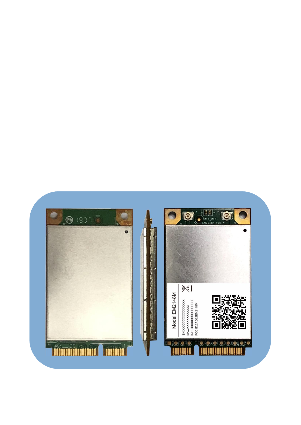
Dimensions
51mm x 30mm x 4.9mm
Card Type
Full-Mini Card (52Pin)
RF Connector
MHF I/MHFII
UE-Category
3GPP R9, CAT 4
USIM
1.8V/3.0V USIM
USB Version
USB 2.0 HIGH SPEED
Power Supply
3.3V±9%
LED Indicators
SIM/PWR/LTE Signal
Weight
About 25g
Basic Specifications
3

Item
Description
LTE Mode
TDD
LTE Bands
B53 DL/UL : 2483.5MHz ~ 2495MHz
TXRX
1T2R
Peak Rate
10MHz:
SA1: DL 40 Mbps, UL 6.8 Mbps
SA2: DL 54 Mbps, UL 3.4 Mbps
5MHz:
SA1: DL 20 Mbps, UL 3.3 Mbps
SA2: DL 27 Mbps, UL 1.6 Mbps
Channel Bandwidth
5MHz/10MHz
Modulation
UL: QBSK, 16QAM
DL: QBSK, 16QAM, 64QAM
Receive Sensitivity
-95dBm @ QPSK, 10MHz, 25°C
MAX Output Power
22dBm (±2)/TX ANT (Note 2)
LTE Specifications
Note 2: EIRP Limit is 36dBm, EIRP =Max Output Power+ Antenna Gain, Antenna Gain≤10dBi is recommended.
4

Item
Description
Operating Temperature
-40°C to 45°C
Storage Temperature
-40°C to 70°C
Operating Humidity
5% to 95%
Environmental Specifications
5

Pin
Standard Pin
Module Pin
Description
I/O
Remark
1
WAKE#
LTE_READY
Wake up the system
host
DO
3.3V
2
3.3Vaux
3V3_IN
3.3V supply
DI
3.3V±9%
3
COEX1
NC
Optional:UART1_SOUT
DO
1.8V
4
GND
GND
Ground
Ground pin
5
COEX2
NC
Optional: UART1_SIN
DI
1.8V
6
1.5V
NC
7
CLKREQ#
NC
PIN Configuration Diagram
6

Pin
Standard Pin
Module Pin
Description
I/O
Remark
8
UIM_PWR
SIM_VCC
USIM card power supply
DO
3V/1.8V
9
GND
GND
Ground
Ground pin
10
UIM_DATA
SIM_IO
USIM card data signal
DI/DO
3V/1.8V
11
REFCLK-
NC
Optional:UART0_SO
DO
1.8V
12
UIM_CLK
SIM_CLK
USIM card clock signal
DO
3V/1.8V
13
REFCLK+
NC
Optional:UART0_SIN
DI
1.8V
14
UIM_RESET
SIM_RST
USIM card reset signal
DO
3V/1.8V
15
GND
GND
Ground
Ground pin
16
UIM_VPP
NC
17
Reserved*(UIM_C8)
SIM_DETECT_
C8
DI
18
GND
GND
Ground
Ground pin
19
Reserved*(UIM_C4)
SIM_DETECT_
C4
DI
20
W_DISABLE#
W_DISABLE
Active low signal. This
signal is Used by the
system to disable radio
operation on add-in
cards that implement
radio frequency
applications.
DI
0:Active
1:3.3V
7

Pin
Standard Pin
Module Pin
Description
I/O
Remark
21
GND
GND
Ground
Ground pin
22
PERST#
EXT_RESET
Module resetting
DI
3.3V
23
PERn0
NC
24
+3.3Vaux
3V3_IN
3.3V supply
3.3V±9%
25
PERp0
NC
26
GND
GND
Ground
Ground pin
27
GND
GND
Ground
Ground pin
28
+1.5V
NC
29
GND
GND
Ground
Ground pin
30
SMB_CLK
NC
31
PETn0
NC
32
SMB_DATA
NC
33
PETp0
NC
34
GND
GND
Ground
Ground pin
35
GND
GND
Ground
Ground pin
36
USB_D-
USB_D-
DI/DO
8

Pin
Standard Pin
Module Pin
Description
I/O
Remark
37
GND
GND
Optional: NC
(Note 3)
PCI Express ®Mini
Card
Electromechanical
Specification
Revision 1.1:
Reserved
38
USB_D+
USB_D+
DI/DO
39
+3.3Vaux
3V3_IN
Optional: NC
(Note 3)
DI
PCI Express ®Mini
Card
Electromechanical
Specification
Revision 1.1:
Reserved
40
GND
GND
Ground
Ground pin
41
+3.3Vaux
3V3_IN
Optional: NC
(Note 3)
DI
PCI Express ®Mini
Card
Electromechanical
Specification
Revision 1.1:
Reserved
42
LED_WWAN#
NC
43
GND
GND
Optional: NC
(Note 3)
PCI Express ®Mini
Card
Electromechanical
Specification
Revision 1.1:
Reserved
44
LED_WLAN#
NC
45
Reserved
NC
46
LED_WPAN#
NC
9

Pin
Standard Pin
Module Pin
Description
I/O
Remark
47
Reserved
NC
48
+1.5V
NC
49
Reserved
NC
50
GND
GND
Ground
Ground pin
51
Reserved
NC
Optional: Module Boot
Mode selection
(Note 3)
DI
0:boot in FFH mode
1:boot in FFF
mode(default)
52
+3.3Vaux
3V3_IN
3.3V supply
DO
3.3V±9%
Note 3: Optional setting: Supported by change BOM.
10

Models
Description
EM2148M
LTE Wireless Communication Module (LTE Wireless
Communication Module, Mini-PCIE,TDD B53, CAT4,
1T2R)
Model List
Regulatory Compliance
FCC Compliance
This device complies with part 15 of the FCC Rules. Operation is subject to the
following two conditions: (1) This device may not cause harmful interference, and (2)
this device must accept any interference received, including interference that may
cause undesired operation.
Any Changes or modifications not expressly approved by the party responsible for
compliance could void the user's authority to operate the equipment.
This equipment has been tested and found to comply with the limits for a Class B
digital device, pursuant to part 15 of the FCC Rules. These limits are designed to
provide reasonable protection against harmful interference in a residential installation.
This equipment generates uses and can radiate radio frequency energy and, if not
installed and used in accordance with the instructions, may cause harmful
interference to radio communications. However, there is no guarantee that
interference will not occur in a particular installation. If this equipment does cause
harmful interference to radio or television reception, which can be determined by
turning the equipment off and on, the user is encouraged to try to correct the
interference by one or more of the following measures:
Reorient or relocate the receiving antenna.
Increase the separation between the equipment and receiver.
Connect the equipment into an outlet on a circuit different from that to which the
receiver is connected.
Consult the dealer or an experienced radio/TV technician for help.
11

Warning
This device complies with part 15 of the FCC Rules. Operation is subject to the following two conditions: (1)
This device may not cause harmful interference, and (2) this device must accept any interference received,
including interference that may cause undesired operation.
Changes or modifications not expressly approved by the party responsible for compliance could void the
user's authority to operate the equipment.
NOTE: This equipment has been tested and found to comply with the limits for a Class B digital device,
pursuant to Part 15 of the FCC Rules. These limits are designed to provide reasonable protection against
harmful interference in a residential installation. This equipment generates, uses and can radiate radio
frequency energy and, if not installed and used in accordance with the instructions, may cause harmful
interference to radio communications. However, there is no guarantee that interference will not occur in a
particular installation. If this equipment does cause harmful interference to radio or television reception, which
can be determined by turning the equipment off and on, the user is encouraged to try to correct the interference
by one or more of the following
measures:
-- Reorient or relocate the receiving antenna.
-- Increase the separation between the equipment and receiver.
-- Connect the equipment into an outlet on a circuit different from that to which the receiver is
connected.
-- Consult the dealer or an experienced radio/TV technician for help.
FCC Radiation Exposure Statement
The modular can be installed or integrated in mobile or fix devices only. This modular cannot be installed in
any portable device, for example, USB dongle like transmitters is forbidden.
This modular complies with FCC RF radiation exposure limits set forth for an uncontrolled environment.
This transmitter must not be co-located or operating in conjunction with any other antenna or transmitter. The
maximum allowable antenna gain is 10dBi. This modular must be installed and operated with a minimum
distance of 20 cm between the radiator and user body. The allowed antenna type is external antenna.
If the FCC identification number is not visible when the module is installed inside another device, then the
outside of the device into which the module is installed must also display a label referring to the enclosed
module. This exterior label can use wording such as the following: “Contains Transmitter Module FCC ID:
2AG32EM2148M .
When the module is installed inside another device, the user manual of this device must contain below
warning statements;
1. This device complies with Part 15 of the FCC Rules. Operation is subject to the following two
conditions:
(1) This device may not cause harmful interference.
12

(2) This device must accept any interference received, including interference that may cause
undesired operation.
2. Changes or modifications not expressly approved by the party responsible for compliance could void
the user's authority to operate the equipment.
The devices must be installed and used in strict accordance with the manufacturer's instructions as
described in the user documentation that comes with the product.
3. List of applicable FCC rules
This module has been tested and found to comply with part 25 requirements for Modular Approval.
The modular transmitter is only FCC authorized for the specific rule parts (i.e., FCC transmitter rules)
listed on the grant, and that the host product manufacturer is responsible for compliance to any other
FCC rules that apply to the host not covered by the modular transmitter grant of certification. If the
grantee markets their product as being Part 15 Subpart B compliant (when it also contains
unintentional-radiator digital circuity), then the grantee shall provide a notice stating that the final host
product still requires Part 15 Subpart B compliance testing with the modular transmitter installed.
13
 Loading...