


ATOM OD06 - EG7010C-M11 USER Manual
01
All rights reserved © Baicells Technologies Co., Ltd.
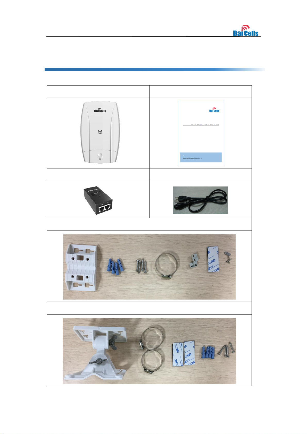
EG7010C
Quick Guide
PoE Adapter
Power Cord
Standard Mounting Kits
Optional Mounting Kits
1. Shipping List
Make sure you have got the following parts:
2
Identity
Description
Color
Status
Description
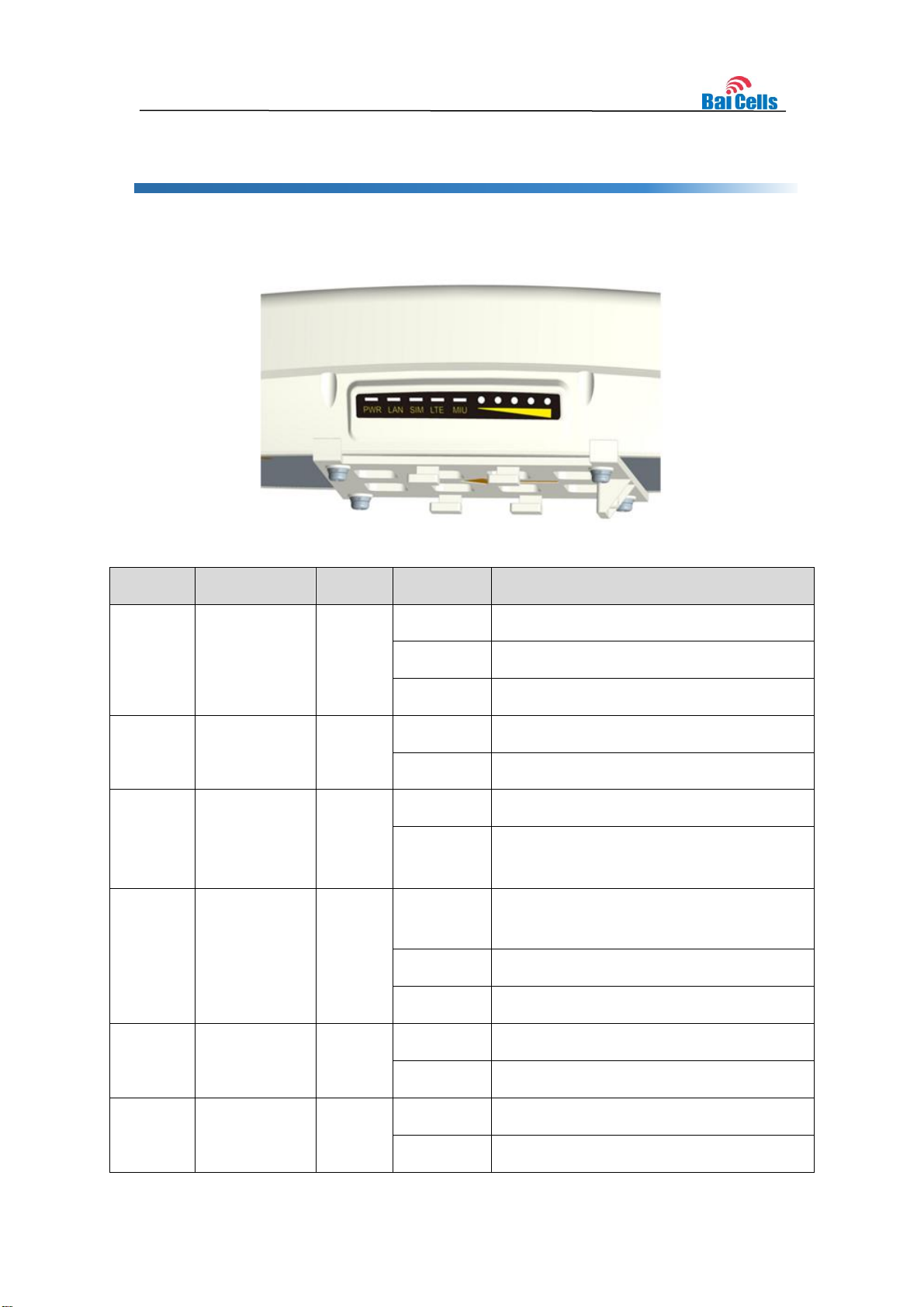
MIU
-
Yellow
OFF
Reserved.
Steady On
Reserved.
Blanking
Reserved.
LTE
Network state
Indicator
Blue
OFF
LTE disconnected.
Steady On
LTE connected.
SIM
SIM card
status
indicator
Yellow
Steady On
The SIM card is normal.
Blanking
The SIM card is abnormal or not
inserted.
LAN
100Mbps Eth
Indication
Yellow
OFF
Ethernet connection does not
established.
Steady On
Ethernet connection is normal.
Blanking
Data is transmitting.
PWR
Power
Indicator
Yellow
OFF
No Power Supply
Steady On
Power On
LTE
Signal
5 LTEs,
Indicate
Green
All OFF
Signal is too weak to attach.
Steady On
According to signal strength in turn light
2. Hardware Introduction
2.1 Indicators
Identity
Description
Color
Status
Description
connection
state and
signal
strength
up
Blanking
Scanning the LTE network
The CPE is authenticating.
CPE is getting IP address from the LTE
network.
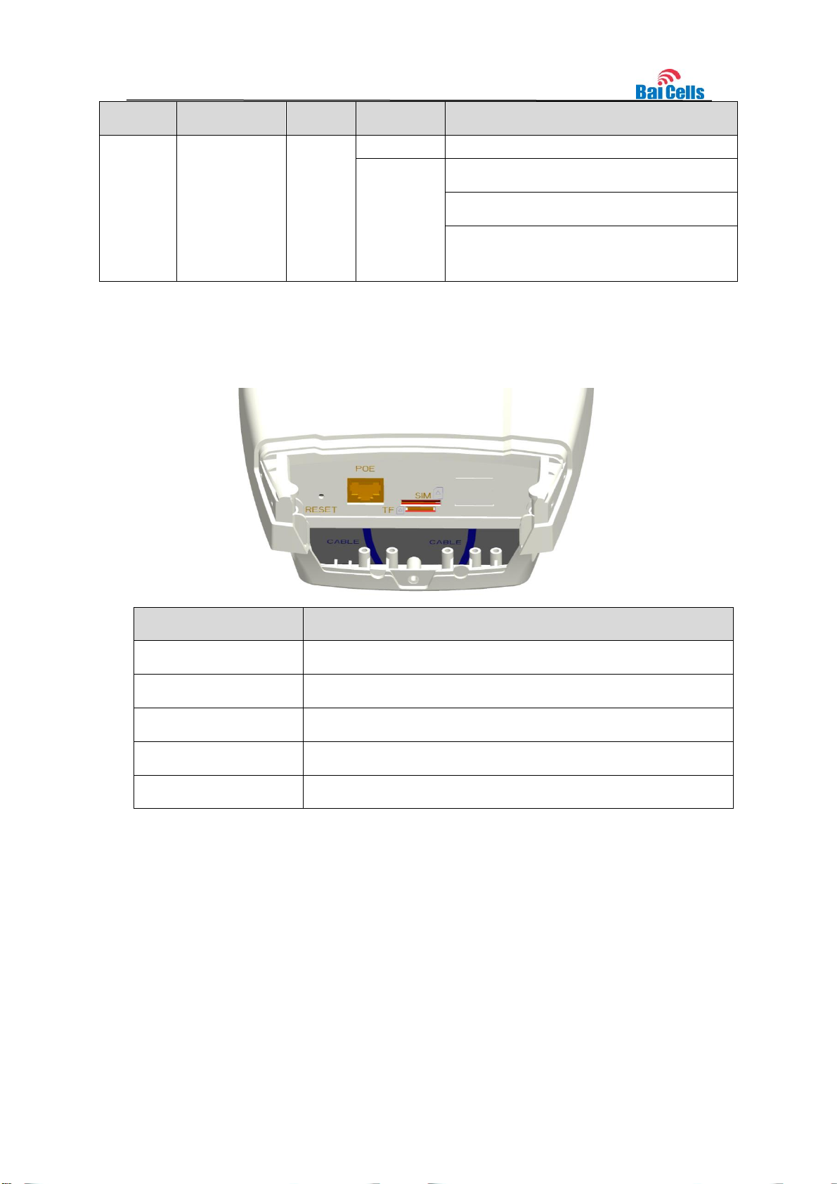
Interface & Button
Description
PoE
Connected to the PoE Power Adapter
TF
Support SD card
SIM
Support 1.8V/3.0V USIM 2FF
RESET
Long press over 10 seconds to restore the factory settings
GND
Connected to Earth by conductor
2.2 Interface and Buttons

Item
Description
Ethernet cable
Outdoor Shield CAT5E
Shorter than 330 feet
Ground wire
16mm² yellow-green wire
(1) Screw the screw on the waterproof
cover, and open the waterproof cover
(2) Insert the USIM card to the USIM
slot. Note following the directions
(3) Connect the Ethernet cable to the PoE
port
(4) connect the ground cable to the
ground screw
(5) Close the waterproof cover and fasten the screw on the cover.
(6) Connected Ethernet cable to the power adapter.
Pay attention to the power adapter interface directions.
(7) Power on, the LED indicator will light up.
3. Installation Guide
3.1 Support Materials
Before installation, prepare the following support materials accordingly, as given below:
3.2 Install USIM Card and Cables

4. Configuration Guide
4.1 4.1 Login
The CPE manages, configures, and maintains the device by web management page. The
steps to log in are as follows:
1. In the address column of browser, type in http://192.168.150.1, then press “Enter”:
2. Enter the user name and password, click "LOGIN". After password authentication,
you can log on to the web management page.
The default user name and password is admin.
For security, it is recommended that you open the firewall, and keep your login password,
WLAN FTP passwords and password well.
4.2 View Status
In the overview area, you can view the device information and LTE status,such as Product
name, Software version, PLMN, IMSI, RSRP, RSRQ, CINR, SINR, Tx Power, Cell ID, PCI,
and so on, as shown below:

Item
Description
UE-Category
3GPP R10, CAT 6/7
USIM Slot
1.8V/3.0V USIM 2FF
Ethernet Port
1 RJ45, LAN, 10/100/1000 auto-sensing, auto-MDX,
PoE
Power Supply
Input: Universal range 100V~240V AC
Output: PoE (24V DC, 0.5A)
Reset Button
Tactile button. Long press over 10s to restore the
factory settings
LED Indicators
MIU/LTE/SIM/LAN/PWR/LTE Signal
Dimensions
241mm (H) x 154mm (W) x 50mm (D)
Weight
About 900 g
Item
Description
LTE Mode
LTE-TDD
LTE Bands
Band 48
TXRX
2T4R
5. Specifications
Basic Specifications
LTE Specifications

Channel Bandwidth
5MHz, 10MHz, 15MHz, 20MHz
Modulation
QPSK, 16QAM
Receive Sensitivity
-94dBm @ QPSK,20MHz, 25°C
MAX Output Power
26dBm
Antenna Type
Internal directional-antenna
Antenna Gain
11dBi@3.xGHz, 2 Ports
Polarization
±45°
Antenna Efficiency
>70%
Isolation
≤-25dB
VSWR
≤2
Horizontal Beam Width (3dB)
60±3°@3.xGHz, 2 Ports
Vertical Beam Width (3dB)
25±5°@3.xGHz, 2 Ports
Item
Description
Language Support
English/Chinese
Network Mode
NAT/Bridge/Tunnel
IP Protocol
IPv4/IPv6
SIM Management
PIN Management, SIM Lock
Network Connection Management
Auto/Manual
LTE Scan Mode
Full band scan, Frequency Lock
WLAN
WPS
MSSID Isolation
VLAN
SW Specifications

VPN
L2TP
GRE
NAT
Port forwarding
DMZ
ALG
Port Trigger
Firewall
IP/MAC/URL Filter
Access Control
Block Port Scanner / SYN Flood
SPI Filter
Network Management
TR069
SNMP
Diagnostics
TCPDump
Ping
Trace route
Statistics
LTE Status/Connection Time/System Up Time
Device Status
DHCP Client List
WiFi Station List
LTE Status
Firewall Status
Maintenance
Date & Time setting
Reboot
Restore factory settings
Restore / Back up configuration file
Firmware upgrade locally/OTA (over the air)
System Log
Operating Log
Run-time Log
Filter/Select/Display/Export Log
Item
Description
Operating Temperature
-40°C to 55°C
Storage Temperature
-40°C to 70°C
Environmental Specifications

Item
Description
Operating Humidity
5% to 95%
Ingress Protection Rating
IP65

6. Regulatory Compliance
FCC Compliance
This device complies with part 15 of the FCC Rules. Operation is subject to the following two conditions:
(1) This device may not cause harmful interference, and (2) this device must accept any interference
received, including interference that may cause undesired operation.
Any Changes or modifications not expressly approved by the party responsible for compliance could void
the user's authority to operate the equipment.
This equipment has been tested and found to comply with the limits for a Class B digital device, pursuant
to part 15 of the FCC Rules. These limits are designed to provide reasonable protection against harmful
interference in a residential installation. This equipment generates uses and can radiate radio frequency
energy and, if not installed and used in accordance with the instructions, may cause harmful interference
to radio communications. However, there is no guarantee that interference will not occur in a particular
installation. If this equipment does cause harmful interference to radio or television reception, which can
be determined by turning the equipment off and on, the user is encouraged to try to correct the
interference by one or more of the following measures:
Reorient or relocate the receiving antenna.
Increase the separation between the equipment and receiver.
Connect the equipment into an outlet on a circuit different from that to which the receiver is
connected.
Consult the dealer or an experienced radio/TV technician for help.
Warning:
This equipment complies with FCC radiation exposure limits set forth for an uncontrolled environment.
This equipment should be installed and operated with minimum distance 20cm between the radiator &
your body.
1
 Loading...