


Operating Manual BaehrTec A1200 / A2000
English – V100 - Date 09/2017 Page 1/64
BaehrTec
A1200
/
A2000
Dry technology pedicure device
with hand piece
Operating Manual

Operating Manual BaehrTec A1200 / A2000
Page 2/64 English – V100 - Date 09/2017
1 Table of Contents
Page
1
Table of Contents ........................................................................................................ 2
2 Note to users ................................................................................................................ 4
2.1 Symbols ............................................................................................................... 5
2.1.1 Symbols in these operating instructions ................................................ 5
2.1.2 Type rpm with output details .................................................................. 5
2.1.3 Symbols on the packaging .................................................................... 6
2.1.4 Differences between BaehrTec A1200 and BaehrTec A2000 .............. 7
2.2 Foreword ............................................................................................................. 9
2.3 General product description and application purpose ...................................... 10
2.3.1 Operator requirem ents......................................................................... 10
2.3.2 Staff and Patient Protection ................................................................. 10
2.3.3 Information on electromagnetic compatibility ...................................... 12
2.3.4 Safety notices ...................................................................................... 12
3 Before using the de vice for th e fir st t im e ............................................................... 13
3.1 Scope of delivery ............................................................................................... 13
3.2 What to observe before every use! ................................................................... 13
4 Device descripti o n ..................................................................................................... 17
4.1 Description control unit ...................................................................................... 17
4.1.1 Front view BaehrTec A1200 ................................................................ 17
4.1.2 Front view BaehrTec A2000 ................................................................ 18
4.1.3 Side view with handpiece holder ......................................................... 19
4.1.4 Side view with dust bag lid (closed) .................................................... 20
4.1.5 Side view without dust bag lid and turbine protection filter (open) ...... 21
4.1.6 Dust bag lid (inside) ............................................................................. 22
4.1.7 Rear view ............................................................................................. 23
4.1.8 Bottom view ......................................................................................... 24
4.2 Description of the handpiece ............................................................................. 25
4.3 Description non-heating device connecting cable ............................................ 27
4.4 Description of suction system ........................................................................... 28
4.5 Colour displa y .................................................................................................... 30
4.5.1 Work mode ........................................................................................... 30
4.5.2 Adjustment mode (Op t ion s Men u) ....................................................... 31
4.6 Home function (butt on (17)) .............................................................................. 33
4.7 Memory buttons (b utt ons (2 9) - (31)) ................................................................ 33
4.8 Disconnecting/connecting the dust bag lid to the controller ............................. 34
4.8.1 Disconnecting ...................................................................................... 34
4.8.2 Disconnecting ...................................................................................... 34
4.9 Changing the filter ............................................................................................. 35
4.9.1 Changing the dust bag......................................................................... 36
4.9.2 Changing the turbine protection filter .................................................. 37
4.9.3 Changing the filter cartridge ................................................................ 38
4.10 Getting started ................................................................................................... 40
4.11 Accessories ....................................................................................................... 43
4.11.1 Foot pedal (BaehrTec A2000 only) ..................................................... 43
5 Servicing and care ..................................................................................................... 44
5.1 Safety notices .................................................................................................... 44

Operating Manual BaehrTec A1200 / A2000
English – V100 - Date 09/2017 Page 3/64
5.2 Care (Disinfection) ............................................................................................. 45
5.3 Guarantee.......................................................................................................... 45
5.4 Recycling/disposal ............................................................................................. 46
5.5 Self-help in the event of malfunctions ............................................................... 47
5.5.1 Change fuse......................................................................................... 49
5.5.2 Cleaning the handpiece button ............................................................ 49
5.5.3 Changing the dampers for the handpiece case .................................. 51
5.5.4 Easy-Clean clamping mechanism ....................................................... 53
5.5.5 Instrument changing aid (insertion and removal aid for very small
instruments) 56
6 Technical Data ........................................................................................................... 59
7 Spare parts/accessories ........................................................................................... 63

Operating Manual BaehrTec A1200 / A2000
Page 4/64 English – V100 - Date 09/2017
2 Note to users
This oper ating ma nual mus t be rea d throug h thorou ghly bef ore using the de vice for
the first time and the cont ain ed instructions and rules must be precisely observed.
These oper ating instru ctions form part of the de vice user agre ement. By thor oughly
reading them, you will be familiarised fully with the functioning and operation of the
device and will therefore be able to recogni se and av o id ope rat i ng err or s, da ng e rs and
damage.
Please retain these operating instructions in a safe place with the device.
Please read these operating instructions carefully.
Please keep these operating instructions for reference purposes – also i n case you w ish
to clean the device.
Please observe all warnings and instructions in these operating instructions and on the
device.
If you ever clean the device, the power supply must be disconnected fully. Remove the
power plug from the safet y outlet. When cleaning / disinfecting, please observe the
notes described in chapter 5 and its subchapters.
Do not place th e device near heat s ources, such as radi ators, air-conditi oning units,
refrigerators and the like. Please also avoid positioning near to water sources (for
example sinks) and / or chemicals. Ensure an appropriately hygienic environment.
Place the device on a firm, no n-slip base. A void pl acing it on unst able tabl es, cart s or
the like. If the device falls, this can cause severe damage and injuries.
To guarantee that the device functions reliably, protect it from cold, and also from
overheating. Therefore, avoid temperatures below +10° C and above +35° C.
Should you use an e xtensi on c able, ens ure th at the overall po wer su ppl y is n ot high er
than the capacity of the extension cable. Please understand that we cannot accept any
liability for accessories of any kind not included in the scope of delivery. This also applies
to any consequential damages that may occur.
Please avoid:
Touching plug contacts with sha rp an d / or metall ic obj ects .
Placing water, beverages and other liquids close to the device.
Leaving children uns upervised with the device.
Touching the mains plu g wit h wet and / or damp ha nds .
Please do not carry out any repairs on the devi ce yourself, as this will result in the
cancellation of the guarantee claim. For all repairs, please contact qualified experts who
are authorised to carry the se out. If necessary, pleas e ask the manufacturer or the
distributor of the device (see rpm on the device).
On the basis of the risk assessment already implemented we have noticed that (electro)
magnetic fields can lead to interference. Therefore, when using the device, please
switch off all devic es an d equipm ent ( mobile telephon es, W LAN, etc .) com pletely that
generate or coul d genera te such fiel ds. Should t his not be f easible, t hen the dis tance
between the A1200/A2000 and these devices must be at least 50 cm in order to prevent
malfunctions.

Operating Manual BaehrTec A1200 / A2000
English – V100 - Date 09/2017 Page 5/64
Please do not use the device in the following cases, and contact the manufacturer:
If the power cable / insulation shows signs of damage.
If the device was exposed to moisture and / or wetness.
If the device has been dropped and / or if the device housing is damaged.
In the event of lighting strike and / or surge, the device may be damaged. For this reason, we
also recomme nd installing surg e protection and rem oving the plug d uring a storm and / or
after a long period of non-use in order to protect the device from voltage peaks.
Please obse rve the cus tomary po wer sup ply specifi cations b efore conn ecting t he device to
the mains.
Before using t he devic e, be s ure to observe s ection " Differ ences bet ween Ba ehrTec A 1200
and BaehrTec A2000".
2.1 Symbols
2.1.1 Symbols in these operating instructions
Warning!
This symbol in dicates a da nger t o hum ans or th e devic e. T his sym bol mu st al ways be gi ven
the utmost at tention. R ead the cor respondi ng sections especiall y carefull y and adhe re very
strictly to the specifications.
This symbol pro vides es peciall y useful advic e and gives additio nal info rmation on operati ng
the device.
CE mark (Communauté Européenne) with the number of the certification authority. A product
bearing this mark meets t he req uirem ents of t he c orresp ondin g EU guid elin e (the a pplic abl e
European Standard).
2.1.2 Type rpm with output details
Fig. 1a
BaehrTec A1200
Fig. 1b
BaehrTec A2000

Operating Manual BaehrTec A1200 / A2000
Page 6/64 English – V100 - Date 09/2017
CE mark (Communauté Européenne) with the number of the certification authority. A product
bearing this mark meets t he req uirem ents of t he c orresp ondin g EU guid elin e (the a pplic able
European Standard).
Application part of type B
This applicati on part guaran tees protec tion against elec tric shock du e to the compl iance of
the leakage currents with standards (Type B).
It is a mandatory requirement that these operating instructions are read and observed before
using the device.
Electrical/electronic waste. Devices with this mark must be disposed of properly and must not
be put in household waste.
This symbol indicates which fuse(s) is are used in the device.
Protection class II
This is a device of protection class II with functional earthing.
ON (max) / OFF (min)
Indicates how the device should be operated.
The following applies to the device:
Operating time: 15 minutes (maximum) pause time: 10 min (minimum)
These approved operating times correspond to the common work procedure in
podiatry/pedicure.
Functional earthing
This symbol i ndicates that th e power suppl y is earthed (the rpm is located directly on the
power supply unit).
Manufacturer
2.1.3 Symbols on the packaging
Transport upright (up = in direction of arrow)
Protect from impacts!

Operating Manual BaehrTec A1200 / A2000
English – V100 - Date 09/2017 Page 7/64
Protect from wetness!
Permitted temperature range: -10°C to +40°C
Permitted humidity range: 30% to 85%
800 hPa - 1060 hP a
Permitted air pressure: 800 hPa - 1060 hPa
2.1.4 Differences between BaehrTec A1200 and BaehrTec A2000
BaehrTec A1200
BaehrTec A2000
Speed range handpiece moto r
6,000 – 35,000 rpm
6,000 – 40,000 rpm
The speeds (rpm) of the handpiece motor can be selected directly on the front controls
6,000
6,000
10,000
10,000
15,000
15,000
20,000
20,000
25,000
25,000
30,000
30,000
32,500 (Fig. 4a (11))
35,000 (Fig. 4b (11))
35,000 (Fig. 4a (12))
40,000 (Fig. 4b (12))
Setting the speeds (rpm) of the handpiece motor using the buttons (27) and (28) (Fig. 4a
and 4b)
1,000 rpm increments (6,000 to 31,000)
1,000 rpm increme nts fro m 6,0 00 to
40,000
31,000 32,500
32,500 34,000
34,000 35,000
Maximum vacuum
-30 mbar (setting 1) to -70 mbar (setting 6)
-35 mbar (setting 1) to -100 mbar (setting
6)
Memory buttons
2 memory buttons (Fi g. 4a (29) + (30))
3 memory buttons (Fi g. 4b (29) + (30) +
(31))
Foot pedal operation
This device cannot be operated
by foot pedal. There is no connection on
the back of the device
(see Fig. 9 (48))
This device can be operated by foot pedal.
There is a connection on the back of the
device
(see Fig. 9 (48))
For details about the speeds of the handpiece motor and suction please see chapter
"Technical Data".
Please particularly note the differences between the BaehrTec A1200
and BaehrTec A 2000 when using instrum ents and when adjusting
the handpiece speed.
All descripti ons r el at ed to t he foot peda l ap pl y t o t he BaehrTec A 20 00 only,
not the BaehrTec A1200.

Operating Manual BaehrTec A1200 / A2000
Page 8/64 English – V100 - Date 09/2017
Unless otherwis e specified, all images belo w always sho w the BaehrT ec
A2000.

Operating Manual BaehrTec A1200 / A2000
English – V100 - Date 09/2017 Page 9/64
2.2 Foreword
Dear customer!
We are delighted that you have chosen to purchase this foot care dry technology device. The
BaehrTec A1200/A2000 boasts technical features that will help to enhance your work.
The BaehrTec A 12 00/A 2000 is mad e fr om m any high-qu alit y alum ini um, st ainl ess-steel a nd
plastic parts which are also us ed in sports c ar and airc raft constr uction and t hus guarante e
the ultimate stability and quality. Furthermore, the micro-processor-controlled electronics
ensure maximum power and performance from the electronic components.
In addition, the BaehrTec A1200/A20 00 has an electronic re adjustment for the han dpiece
motor, which provides power and performance even in the lowest rotation speed range. Try it
for yourself – you'll be amazed.
Another highli ght is the E asy-Speed conc ept. Thanks t o the instrument illustrations on the
controller, sett ing the engine s peed for the instrum ent currently in us e is guaranteed to be
child’s pla y (ho w ev er, t his i s no substitute fo r the user c h eck i ng tha t the maxi m um spe ed fo r
the instrument currently in use is not exceeded).
In addition t o th e easy-speed c o nce pt, the Ba ehrT e c A1200/A200 0 ha s a colour dis pl a y that
provides you with further info rmatio n and whic h will facili tate adjus ting some device set tings
(e.g. colour background).
Modern electronic devices typically have energy-saving features. This is why we have
purposely no t inclu ded a standb y funct ion on the Ba ehrTec A 1200/A 2000. There fore, when
your device is not required, please turn it off using the main switch, which is located in a userfriendly position on the front of the device. Protect the environment and your purse.
The BaehrTec A1200/A2000 has the following outstanding advantages:
- very low weight
- very low noise level
- simple operating with a hi g h de gr e e of operati ng sa fe ty
- high performance, perfectly adj ust ed to the w ork i ng con dit io ns
- high robustness (for mobile use)
- high and long reliability
- high energy-s a vi n g po tential (no standby mode)
- Button on handpiece
The BaehrTec A1200/A2000 foot care device has been made and tested in accordance
with strict quality criteria, and it complies with Directive 93/42 EEC for medical devices.
We hope your n e w dev ice brings you p lenty of enjoyme nt a nd w e wis h you every success in
operating it.
Your
Gustav Baehr GmbH

Operating Manual BaehrTec A1200 / A2000
Page 10/64 English – V100 - Date 09/2017
2.3 General product description and application purpose
The BaehrTec A1200/A2000 foot care device is intended for use in medical foot care. It must
only be used by trained pr ofe ssi o nals .
Rotating instruments (grinder, files, etc.) are actuated with the BaehrTec A1200/A2000. These
can be used to strip away hard skin, calluses, nails etc. and remove corns.
In detail, the A1200/A2000 is intended for the following:
• for cleansing and milling the nail fold and removing ingrown nails
• to smooth and strip away mycotic and non-mycotic nails
• to polish non-m ycoti c nai ls w he re ne ce ss ar y
• to remove deep callosities or clavi using the hollow cutter
• milling and smoothing the areas around the digit if these are macerated or calloused
• to smooth plantar soles wi th the twist er or the cut ti ng grinder
• Drill through the nail with a r ound or hollow drill with grinders for clavi or subungual
haematoma
• to roughen the nail in preparation for brace correction
• for preparation in the event of whitlow
• to remove severe plate-like callosities
Other types and fields of application are carried out at your own risk, and may conceal
dangers. No form of misappropriation is permitted.
Improper use may lead to damage to persons or objects.
The manufa cturer c annot be h eld resp onsible f or damages caused by improper use,
unqualified staff or incorrect operation.
All warra nty cla ims are vo id f ollowi ng impr oper use or ope ning t he
device.
WARNING: This device may not be altered without the permission of
the manufacturer.
2.3.1 Operator requirem ents
This device m ust only be used by trained and instructed podiatri sts, medical chi ropodists,
doctors or persons in related occupational categories. They must be familiar with the
appropriate work ing method and have a rel ev ant qu al ifi ca tion.
The operator is obliged to/must ensure that
• only fault-free and flawless work equipment is used
• protects himself, the patient and others from dangers
• contamination through the device is avoided
2.3.2 Staff and Patient Protection
It is essential that you read this section with the utmost care! It contains
important information on protecting yourself, others and the device
from damage!

Operating Manual BaehrTec A1200 / A2000
English – V100 - Date 09/2017 Page 11/64
• Only use high-quali t y rotati ng inst rument s wi th st andar dis ed sh aft ( diamet er 2.35 mm )
from the Baehr product range.
• Please observe the specific instructions of rotating instruments when using them. Above
all, observe the manufacture r' s i nf o rm a tion o n m aximum spee ds, cleaning, disinfection
and sterilisation.
• Disinfect, clean and sterilise the instruments after each use.
• Only use cl eaned, disinfect ed and steri lised inst ruments for each change of patient to
avoid a possible transfer of germs to the next patient.
• Disinfect the handpiece after each use and before each change of p atient. (Please
ensure that no disinfecting agent or other liquid can enter the device).
• Disinfect all parts of th e device that could h ave come into contac t with contam inated
patients after each use and before each change of patient. (Please ensure that no
disinfecting agent or other liquid can enter the device).
• The operating staff must wear protective gloves as well as eye, mouth and nose
protection when using the device.
• When using the de vice, the staff m ust take car e that neither h air nor any other lo ose
objects such as wipes, cotton wool or the like can enter the area of the rotating tools. A
hair net must be worn where necessary.
• The operating staff must bear in mind that the particles that are removed when working
with the rotati ng tools m ay c hip. Open and unt reat ed wounds on th e pat ient whi ch ar e
in the direct vicini ty of th e work ing are a shoul d the refor e be cove red i n a steril e wa y in
order to protect them from any splintering particles.
• The device m ust be m aintaine d and cl eaned acco rding to the inst ructions be fore an d
after long pauses in use.
• Only accessories authorised for use wit h the device may be used.
• The national statutory provisions must be observed during use, in particular:
the currently applicable work regulations
the currently applicable accident prevention measures
To guarantee constant readiness for operation and preservation of value, the prescribed care
work and maintenance services must be performed.
The device must only be repaired using replacement parts approved by the manufacturer and
in accordance with the manufacturer’s instructions. The recommended maintenance services
(after notification, but at the latest within 24 months) and inspection and repair work must only
be performed by the manufacturer.
This device must not be modified without the permission of the manufacturer.

Operating Manual BaehrTec A1200 / A2000
Page 12/64 English – V100 - Date 09/2017
2.3.3 Information on electromagnetic compatibility
We would lik e to point out that due to EN 6 0601-1 on the electroma gnetic compatibilit y of
electromedical devices that:
• medical, electric devices are subject to particular precautionary measures and so must
be operated according to the requirements of these operating instructions.
• portable and mobile high-frequency communication facilities may affect the functionality
of electrical devices.
• in order to com ply with the E MV requi rement s of EN 6 0601-1, onl y origin al feed lin es,
accessories and spare parts may be used.
Only use manuf act u re r a pp rov ed m ains cables to operate th e de v ice. If you
require a new cabl e, pl ease contact the m anufa ct u rer . Op er ati n g th e devi c e
using a different cable is not permitted.
2.3.4 Safety notices
The device is not authorised for operation in potentially explosive areas.
Before ever y application, the operator must make sure of the functio nal safety and proper
condition of the device.
Improper handling, maintenance and care may lead to premature
deterioration and malfunctions.
This can result in a reduced product life.
Therefore, please clean and care for the device regularly and properly and
have it sent for se rvici ng reg ula rly (obs erve servi ce indi cato r or at t he lates t
within 24 months)!
Damaged functional parts can cause damage or injuries to persons or
objects. Furthermore this may result in (even greater) damage to your device.
Stop working immediately and disconnect the device from the mains when
functional parts are damaged and contact customer service.
Electromagnetic fields may affect the functionality of implanted
systems (e.g. pacemakers).
Please ask your patients be fore beginning the treatme nt whether they
have such a system.
Due to the complex interactions between electric devices and mobile
telephones, it is possible that mobile phones that are switched on may affect
the device, even though the device meets the applicable requirements
relating to electr om agn etic fiel d s.
Do not use your mobile phone while working and also inform your patients
that their mobile phones should be switched off during treatment.
Remove electronic devices, which could cause interaction
(e.g. hearing aids, etc.) while using the devic e.
Otherwise, the distance between the device and the upper part of the body
of the person to be treat ed must be at least 50 cm, in ord er to rule out an y
malfunctions.
If you put the ha ndpiece down t here is risk of i njury when reac hing for the
handpiece. Injuries from used instruments may result in infections.
Please t ake care when setti ng down the handpiec e so that you do not
injure yourself.

Operating Manual BaehrTec A1200 / A2000
English – V100 - Date 09/2017 Page 13/64
3 Before using the de vice for the fir st t im e
3.1 Scope of delivery
Before first use, you should check that all items have been delivered.
Items delivered:
1 piece A1200 or A2000 control unit including handpiece (firmly connected to each other)
1 x operating instructions
1 pc. dust bag microfibre (1 bag already installed)
Art-No.: 21185
1 x turbine protection filter (1 filter is already inserted for you)
Dimensions: (~ 93 x 78 mm)
1 x sound-insulating fleece (1 filter is already inserted for you)
Dimensions: (~ 48 x 57.5 mm )
1 x coarse filter fleece (1 filter is already inserted for you)
Dimensions: (~ 48 x 57.5 mm)
1 x carbon filter fleece (1 filter is already inserted for you)
Dimensions: (~ 48 x 57.5 mm )
1 x ultra-fine filter fleece (1 filter is already inserted for you)
Dimensions: (~ 48 x 57.5 mm )
2 x carbon filter foam (2 filters are already inserted for you)
Dimensions: (~ 48 x 57.5 mm )
1 x power cable with straight connector
Art No. 20970006
1 x Easy-Clean tool kit for BaehrTec A2000
Art No.40285
1 x damper for handpiece case (set)
Art-No.: 40286
For more information, please see the section on "Changing the dampers for the
handpiece case".
If your delivery is incom ple te, ple ase inf orm us of this imm ediately.
Please keep t he delivery box along with any packaging acc essories. The
packaging was developed for this device and provides the be st possible
protection during transportation. Therefore, please use the original
packaging shoul d you send your devic e in for servic ing. Ther e shall be no
entitlement to guarantee for any damages that are caused due to inadequate
packaging during transportation.
3.2 What to observe before every use!
It is essen tial tha t you read th is sectio n with th e utmost car e! It cont ains
important information on protecting yourself, others and the device
from damage!
The design atio n BaehrTec A1200/A2000 used in this section refers both to the control
unit and the handpiece.

Operating Manual BaehrTec A1200 / A2000
Page 14/64 English – V100 - Date 09/2017
Before use, please check whether the t ype of current and the mains voltage of t he power
source are s uitable for us ing the devic e. Information on the type o f current and the mains
voltage can be found on the nameplate on the controller.
When setting up t he devic e, ensur e th at it is pl ace d on a l evel base , tha t i t cann ot f all d own
and that the extracted air can escape easily.
Be sure to keep the BaehrTec A1200/A2000 out of reach of children.
Do not expose the device to direct heat sources (heaters, strong sunlight etc.).
Ensure that the power cable is not damaged due to squeezing, snapping or
rubbing on sharp edges. If you notice any damage to the mains cable,
please immediat ely stop wo rking with your device, turn off the main switch
and immediat el y r em ov e th e safety plu g fr om the safet y socket. To be able
to work with the d evice ag ain, pl eas e orde r a new po wer cabl e. T o be able
to work with the device ag ain, please order a new po wer cable. Only use
manufacturer approved mains cables to operate the device. If you require a
new cable, pl ease contact the manufacturer. Operating t he device using
different cables is not permitted.
Never operate the device with a damaged power cable.
Your device has a detachable connector plug mechanism (see section "rear
view")
Please ensure that the device is positioned so that a disconnection is
unlikely at all times.
Do not use the B aehrTec A12 00/A2000 in d amp areas s uch as saunas or
swimm ing complex es. Wetness an d moisture o n the controll er can lead to
dangerous current leaks, which poses the risk of an electric shock.
Disconnect the device immediately from the socket.
Please send the device in for service with a description of the defect.
Avoid significant differences in temperature. This can cause dampness (condensation).
Protect the BaehrTec A1200/A2000 from frost.
The device must b e switched off and disconnecte d from the mains before carrying out any
cleaning/mai nt en anc e wo rk .
Disconnect th e safety plug from t he mains im mediatel y shoul d you disc over an y damage o r
malfunctions of the device.
The manufactu rer acc epts no li abilit y for damag es to o bjects, animals or pers ons which are
caused by incorrect operation of the BaehrTec A1200/A2000.
Please ensure that the BaehrTec A1200/A2000 and the instruments are always in an
immaculate h ygienic c ondition, in order that they do p ut your o wn healt h or that of o thers at
risk. For more information please refer to section "Care (disinfection)" of the BaehrTec
A1200/A2000.
Rings or jewellery worn while working with the device may cause scratches on the handpiece.
Such damage is excluded f rom the guara ntee. Whils t working with t he device, you should
avoid wearing jewellery.
Please onl y work with the suction tur ned on in ord er to s uction off an y path ogen-containing
dust and to prevent the handpiece motor or the handpiece from becoming warm.
Never submerge the device in liquids, and do not suck up any liquids.

Operating Manual BaehrTec A1200 / A2000
English – V100 - Date 09/2017 Page 15/64
If you suck u p any cott on wool , pa pe r o r the like, thi s m a y c au se the suction o penings in th e
handpiece to becom e bloc k ed. Thi s ma y heavi l y affe ct the s uction power.
If the symbol for a fi lte r c ha ng e ap pe ar s on the displa y, it is esse ntial that you change
the dust bag (the display can only function reliably if all filters are correctly applied. Therefore,
only work with th e device if all filters are appl ied). Otherwise the devi ce will automaticall y
switch to suctio n level 3 after ap proximately half a m inute to prevent any d amage to your
device (please refer to section "Filter change" for more information on how to change the dust
bag and the filter).
Never work wit h th e d ev ice if the dust b ag o r th e fi lt er are not ins ert ed, as in such cases , t he
device may be damage d and the guarantee shall expire.

Operating Manual BaehrTec A1200 / A2000
Page 16/64 English – V100 - Date 09/2017
Warning – ri sk of in jury!
As shown in the illustration, you should avoid "pulling motions" during your
work, as this may cause the instruments to slip out.
Please take care not to exert too much pressure when using the
instrument (burns on skin).
Fig. 2 Incorrect opera ti on
Fig. 3 Correct operation

Operating Manual BaehrTec A1200 / A2000
English – V100 - Date 09/2017 Page 17/64
4 Device descripti o n
4.1 Description control unit
4.1.1 Front view BaehrTec A1200
Fig. 4a
(1) Controller housing
Main switch: (2) "ON" and (3) "OFF" with corresponding (4) LE D
(5) – (12) Push buttons for instruments speeds (6,000 – 35,000 rpm) with the
corresponding (5a) – (12a) LEDs
(13) Push button to switch handpiece motor on and off
Push buttons handpiece speed: (14) + and (15) - (1,000 rpm)
(16) Push button for instrumen t di r e ction right/ lef t
(17) Push button "Home"
(18) Push button "Options Menu"
(19) Colour display
(20) Push but t on for o per a ti o n al re a din e s s of su c ti o n
(21) - (26) Pu sh b uttons for "S uct ion level" (Levels 1-6)
Push buttons for "Change of suction level": (27) + and (28) (29) - (30) Push buttons "Memory"

Operating Manual BaehrTec A1200 / A2000
Page 18/64 English – V100 - Date 09/2017
4.1.2 Front view BaehrTec A2000
Fig. 4b
(1) Controller housing
Main switch: (2) "ON" and (3) "OFF" with corresponding (4) LE D
(5) – (12) Push buttons fo r instrument spe eds (6,000 – 40,000 rpm) with the corresponding
(5a) – (12a) LED s
(13) Push button to switch handpiece motor on and off
Push buttons handpiece speed: (14) + and (15) - (1,000 rpm)
(16) Push button for instrument direction right/left
(17) Push button "Home"
(18) Push button "Options Menu"
(19) Colour display
(20) Push but t on for o per a ti o n al re a din e s s of su c ti o n
(21) - (26) Pu sh b uttons for "S uct ion level" (Levels 1-6)
Push buttons for "Change of suction level": (27) + and (28) (29) - (31) Push buttons "Memory"
Operating Manual BaehrTec A1200 / A2000
English – V100 - Date 09/2017 Page 19/64
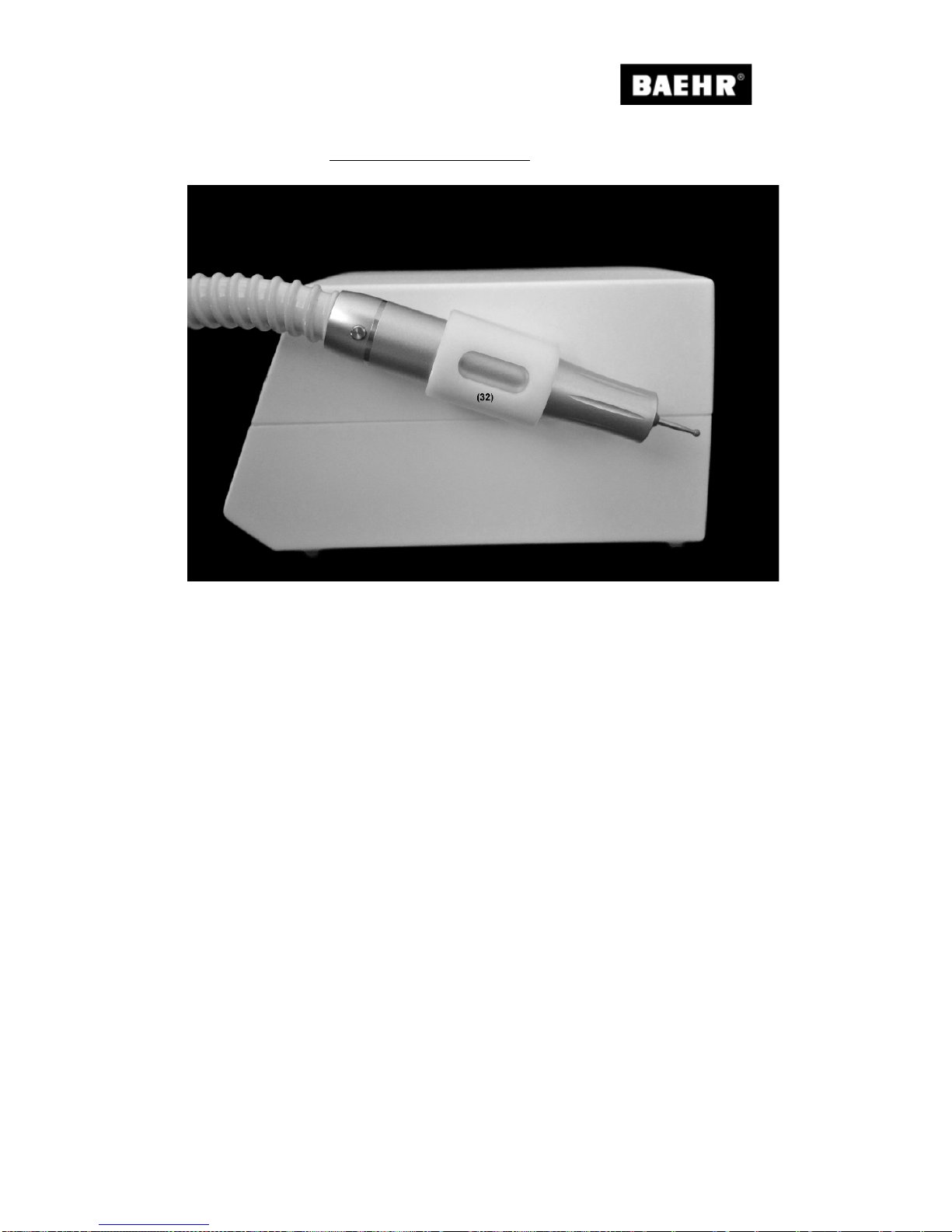
4.1.3 Side view with handpiece holder
Fig. 5
(32) Handpiece holder

Operating Manual BaehrTec A1200 / A2000
Page 20/64 English – V100 - Date 09/2017
4.1.4 Side view with dust bag lid (closed)
Fig. 6
(33) Dust bag lid with handle
(34) Handpiece outlet
(35) Screws for handpiece outlet
Must only be unfastened by the manufacturer
(36) Suction hose

Operating Manual BaehrTec A1200 / A2000
English – V100 - Date 09/2017 Page 21/64
4.1.5 Side view without dust bag lid and turbine protection filter (open)
Fig. 7
(37) 4x magnet hold er
(38) Filter grille

Operating Manual BaehrTec A1200 / A2000
Page 22/64 English – V100 - Date 09/2017
4.1.6 Dust bag lid (inside)
Fig. 8
(39) Receptacle for dust bags
(40) Mounting bolts for magn et holder
(41) Rubber seal for dust ba g lid
(42) Dust bag

Operating Manual BaehrTec A1200 / A2000
English – V100 - Date 09/2017 Page 23/64
4.1.7 Rear view
Fig. 9
When working from the case, we recommend removing the storage tray from
the case in order that the heat created b y the devi ce can escape from the
case and to avoid potential head build-up.
(43) Filter cartridge
(44) Knurled screws
(45) Fuse clip
For microfuses 2x 3.15 A delay (type H)
(46) Power connector
Only connect the connection cable provided or one approved by the manufacturer.
(47a) Nameplate
(47b) Serial no. plate
(48) Connector socket for foot pedal (BaehrTec A200 0 only)

Operating Manual BaehrTec A1200 / A2000
Page 24/64 English – V100 - Date 09/2017
4.1.8 Bottom view
Fig. 10
(49) Housing screws
All housing screws must only be unfastened by the manufacturer.
(50) Housing seal
As soon as the housing seal is breached or removed, all guarantee claims shall expire.
(51) Rubber feet (4 x)

Operating Manual BaehrTec A1200 / A2000
English – V100 - Date 09/2017 Page 25/64
4.2 Description of the handpiece
Fig. 11
(36) Suction hose
(52) Opening for DIN instruments with a shaft diameter of 2.35 mm
(for instruments wit h a ma xim um diameter of 12 mm)
(53) Handpiece ca se (ca n be unscr e wed )
(54) Handpiece cap
(55) Push button

Operating Manual BaehrTec A1200 / A2000
Page 26/64 English – V100 - Date 09/2017
max. instrument diameter no greater than 12 mm
Warning: Always observe the maximum permissible
instrument diameter and the respective maximum
permissible spee d of the in strument manufact ur er .
Please ensure tha t this is never ex ceede d since it can
result in serious injuries to the patient and the
operator. Vibr a t io ns can also occur at the handpie ce .
Please keep your sa fet y and the saf ety of your p atie nt
in mind.
Fig. 12
Do not use any instrumen ts th at are lar ger th an those shown on the front panel of the
device!
Only use diamond and rust-safe
cutters
(not greater than i llustrated)

Operating Manual BaehrTec A1200 / A2000
English – V100 - Date 09/2017 Page 27/64
4.3 Description non-heating device connecting cable
Fig. 13
(56) Device connector
(57) Cable
(58) Safety plug

Operating Manual BaehrTec A1200 / A2000
Page 28/64 English – V100 - Date 09/2017
4.4 Description of suction system
When developi ng the sucti on system of the BaehrT ec A120 0/A200 0 we hav e place d a great
deal of emphasis on oper at in g safety and operating spee d.
We would ther efore like first and foremost to gi ve you an insig ht into the oper ation of the
suction system.
It is possible to work with th e hand piece m otor s witch ed on if t he suc tion i s
disabled.
However, it is not possible to work with the suction enabled, if the handpiece
motor is not running.
As soon as the handpiece motor is in operation, the suction will also always
be turned on automatically (barely noticeable).
We have deliberately chosen to do this because this prevents the handpiece
from becoming warm and also ensures that dust created when working is
suctioned off to a minimum.
If you do not turn on the suction you r self, we shall describ e this in the
following as dea ctivated suct ion. Please be aw are that this is always
running, even if you have not turned it on.
You can set the currently selected suc ti on level usi ng th e button (20) a t any time so th at it is
"Not ready for operation" or "Ready for operation".
"Not ready for operation" means that the suction is not activated while the handpiece motor
is running. This will be indicated on the displ ay if t he ba rs in the b ar gr aph a re pres ente d as
transparent (= sucti o n not re ad y for ope rat io n) .
"Ready for operation" means that the suction is activated while the handp iece motor is
running. Thi s will be indic ated on the di splay if the ba rs in the ba r graph are fill ed blue (=
suction ready for operation).
If you press button (20) while the handpiece motor is running, the suct i on w ill im m edi atel y be
activated/deactivated.
If you press b utton (20) while the hand piece m otor is not runni ng, the s uction will be turned
on or it will remain turned off once you turn on the handpiece motor.

Operating Manual BaehrTec A1200 / A2000
English – V100 - Date 09/2017 Page 29/64
Here, ready for operation does not necessarily mean that the suction is actually active, as the
suction only becomes active when the suction is ready for operation and the handpiece motor
is also in operation.
If the suction is actually active, this will be indicated on the display by two additional symbols.
This symbol is dis pla yed if the sucti on i s not c urrent ly in operati on wi th the
suction level you have set (suction off).
This symbol is dis pla yed if the sucti on i s not c urrent ly in operati on wi th the
suction level you have set (suction on).
(Can only appear while the handpiece motor is running).
Therefore, the following situations are possible:
Handpiece motor
Suction
ready for use
Bar diagram
on the displa y
Suction
Off No Transparent Off
Off
Yes
Filled blue
Off
On
No
Transparent
Off
On Yes Filled blue On
This offers you the following advantage:
If you set the suction so that it is "not ready for operation", you can see which
suction level you last selected at all times. If you then want to set the suction
in the same way, all you need to do is simply press butt on (20) and t he
suction will be ready fo r ope rati on ag ain.
As soon as you press one of the s uction level b uttons (21) – (26), (27) or
(28), this suc tion lev el will immedia tely be set and will als o imm ediatel y be
"ready for use". This mea ns yo u o nl y ever have to pre ss one button.

Operating Manual BaehrTec A1200 / A2000
Page 30/64 English – V100 - Date 09/2017
4.5 Colour displa y
The BaehrTec A 1200/A2000 has two operating m odes, which are indi cated to you on th e
display:
o Work mode
o Adjustment mode (Option s Men u)
4.5.1 Work mode
As the name suggests, you can operate and work with your device in "Work mode". As soon
as you tur n on your device, you will automatic ally be in "Work mode". Here, the foll owing
information will be shown to you in the display
Speed of the handpiece motor
Here you will be shown the rotation speed that is currently set for the handpiece motor.
Handpiece motor/instrument rotation direction
The instrument rotation direction is shown in the display
Direction of rotatio n ri gh t Direction of rotation left
The handpiece motor is in operation when the arrow is shown in blue. The arrow is transparent
when it is not running.
Handpiece motor on Handpiece motor off
Suction
This symbol is dis pla yed if the sucti on i s not c urrent ly in operati on wi th the
suction level you have set (suction off).
This symbol is dis pla yed if the sucti on i s not c urrent ly in operati on wi th the
suction level you have set (suction o n).
(Can only appear while the handpiece motor is running).
For more information, please refer to the previous section.
Speed of the
handpiece motor
Filter control
Service
control
Memory
function
Handpiece
motor/instrument rot ation
Suction level
Suction
Suction level
Foot pedal

Operating Manual BaehrTec A1200 / A2000
English – V100 - Date 09/2017 Page 31/64
Suction level
The suction lev el you have sel ect ed will be shown to you here as tex t a nd as a bar graph. In
the bar graph, you will also see whether the suction is currently activated or deactivated.
For more information, please refer to the previous section.
Filter control
As soon as the por es of t he dust bag b ecome bl ock ed (dus t ba g is full ) this will be sh own to
you in the dis play usi ng th e filter -contr ol symbol . In suc h a ca se, you m ust r eplace t he dus t
bag. (For inform ation o n how to chan ge the dust bag, pl ease r efer to the s ection " Changi ng
the dust bag").
Service Control
The BaehrTec A1200/A2000 has a service interval display. The service interval is 905 hours,
and refers to the o perating hours of th e handpie ce moto r as of the deli ver y/the last service.
You must send your device for s ervicing when the servi ce key lights up on the di splay (or
within 24 month s; this time interval is not displayed b y the device) to avoid elaborate and
costly repai rs an d com ply with t he test regulat ions of you r medi cal device acc ording to V DE
0751-1.
The service inte rval is actuall y 900 hours. B ut as your dev ice alread y has
meter readings at the time of delivery, as described in the following section,
we have incorporated a buffer of 5 hours for you.
Foot pedal (BaehrTec A2000 only)
This symbol appears on the display as soon as the optionally available foot pedal is
connected.
4.5.2 Adjustment mode (Op t ion s Men u)
You can change settings and call up information on your device using the "Adjustment mode".
As soon as you turn on your device, you will automatically be in "Work mode". Then, in order
to exit work mode and reach the options menu, please press the button (18).
For your own safety, it is only possible to exit from the work area and switch
to the options menu when the handpiece motor is turned off.
It will take appro x. a half second to change t o the next menu item when
browsing a m enu point usi ng the butto ns (14) and (15). This ensures tha t
you have enough time to get a look at the choices.
Unlike the set ti ng s you make i n work mode (e xc ept m em o r y fun c tio ns ) , t he
settings you mak e in the optio ns menu will rem ain even af ter switchi ng off
the device.

Operating Manual BaehrTec A1200 / A2000
Page 32/64 English – V100 - Date 09/2017
The options menu is structured as follows
Menu level 1
Menu level 2
Description
Language
- German
- English
- French
- Italian
- Japanese
- Russian
- Spanish
Set the desired language here
Sounds
Different sounds /
sounds off
Here you can select the sound that will
sound when you press a butt on , or you can
switch the sound off.
Colour
Different
background
colours
Select your background colour here
Information
- Operation
- Handpiece
- Turbine
- Service in
- Version
- Information on activation period
- Handpiece motor operating hours
- Operating hours of the turbines
- When is the next service due
= (when will the Service Control
symbol appear)
- Version of your A1200/A2000
Your BaehrTec A 120 0/A200 0 goes thr ough va rious q ualit y con trols prior to
delivery. Amongst other things, your A1200/A2000 will undergo a functional
test during this process . Please do not be surp rised theref ore, if the devic e
already has s ome meter readings . This is perfectly normal and does not
mean that it is a used device.
For reasons of o perational saf ety, we recom mend that you do not turn off
the sounds!
You cannot make any changes in the Information menu item! This item is for
viewing purposes only.
If you exceed t he service interval, n egative val ues will ap pear for " Service
in", and the dev ice will cou nt the operati ng hours that have elapsed since
the last service date.
You can navigate through the options menu using the following buttons
• Options menu button (18)
--> opens the options menu
--> switches from menu level 2 to menu level 1 and back to the work mode.
• Buttons for handpiece speed +/- (14) and (15)
--> browse within men u lev el (cursor )
• Handpiece motor button (13)
Select (Enter) / Access menu level 2
• Home button (17)
--> Return to work mode
The magenta background indicates which menu item you are currently viewing.
The settings that have just bee n made will be in dicated to you by t he "x" o n the right-hand
edge of the display.

Operating Manual BaehrTec A1200 / A2000
English – V100 - Date 09/2017 Page 33/64
4.6 Home function (butt on (17))
This button has two functions:
By briefly p ressing the Hom e butt on yo u will b e tak en directl y from the o ption s menu to the
Work mode (see section "Work mode").
By pressing this but ton f or app roximatel y 5 sec onds, the bas e setti ngs m ade b y the fac tory
will be restored:
• Speed of the handpiece motor = 6,000 rpm
• Instrument rotation direction = clockwise
• Suction level = 4+
• Language = German
• Sound = Aqua
• Background colour = white
The set-up of the base settings cannot be changed.
By press in g the bu t to n f or appr ox . 5 s eco nd s all s ett i ng ar e re set (a l so t he
values of the memory buttons) to the factory settings.
The information (meter readin gs , etc . ) will, of course, remain unaf f ecte d.
4.7 Memory buttons (b utt ons (2 9) - (31))
Your device has two (A 1200) or th ree (A2000 ) memory b uttons whic h you ca n use to s ave
your preferred s et ting s in Work mode. These setti ngs will be retai ne d ev en if you tur n o ff t he
device.
In order to sav e settings, please set them (instr ument rotation speed, i nstrument rotation
direction and suction level ) in Work m ode an d hold the memor y b utt o n whe re you would li k e
to save these sett i ngs for more tha n 2 sec o nds. O nc e th e settings are s ave d, you will h ea r a
sound and the respective memory storage space is shown on the display.
All memory buttons are factory pre-set as follows:
• Handpiece motor speed: 6,000 rpm
• Handpiece motor direction: right
• Suction level: 4+
Please note that the selected adjustments are saved if you keep the memory
button pressed for longer than 2 seconds. This means that settings saved to
this memory button will be lost.
In order to recall settings t hat were saved on a memor y button, briefly press the desired
memory button. T he saved settings ar e then applied. This will be indicated to you on th e
display by showing the corresponding memory button.
Please note that when bri efly pressing the memor y buttons, you will only
hear a sound once you remove your finger from the button.

Operating Manual BaehrTec A1200 / A2000
Page 34/64 English – V100 - Date 09/2017
The indication of t he memo ry b utton will onl y app ear o n the di spla y if you
select the settings via the memory button. If you (accidentally) make
settings that are sav ed t o a m emo ry b utton, you will not be s ho wn on the
display that these settings are already stored on a memory button.
4.8 Disconnecting/connecting the dust bag lid to the controller
Before you remove the dust bag lid from the controller or attach it again, turn
off the devic e at th e main swi tch (3) a nd remove the safet y plug (58) from
the socket.
4.8.1 Disconnecting
In order to disconnect the dust bag lid from the controller, please follow th es e s teps :
1) Hold the dust b ag lid b y the han dle an d lift of f rom the c ontroll er. You will fee l a slig ht
resistance from the magnetic fasteners when lifting it.
4.8.2 Disconnecting
To attach the dust bag lid to the co ntr ol l er pl ea se pr oce ed as foll o ws:
1) First, attach t he dust bag lid with th e mounti ng bolt s for the magnet holde r to the si de
on which the handpie ce outl et is not loc ate d.
2) Then attach t he dust b ag lid with the mounting bolts fo r the mag net hol der to th e side
on which the handpi ece ou tlet is locate d. The m agnets ensure that t he dust bag li d is
pulled towards the housing and thus closed.
Disconnecting Fig. 14

Operating Manual BaehrTec A1200 / A2000
English – V100 - Date 09/2017 Page 35/64
Connecting Fig. 15
When changing t he dust b ag, make sure t hat the dus t bag does not pi nch
between the controller and the dust bag lid. If this should be the case,
remove the dust bag li d onc e agai n an d mak e sure th at t he dust bag is not
pinched when closing.
Before you cl ose th e d us t ba g li d an d r esume your work, always make sure
that the turbi ne protection filter (rectan gular) is insert ed and that you have
attached an undamaged dust bag correctly in the receptacle (39) for the du st
bag (42), so that no impurities can enter the turbine and damage the device.
4.9 Changing the filter
We recommend cha ngi ng the dust bag, as well as all fil te rs reg ul a rl y an d at
least every fo ur we eks, in order t o pre vent exc essive germ b uild-up. T hink
of your health!
Before we desc ribe how to chan ge the filter, we would like to provi de you with som e quick
information on the filtration system in the BaehrTec A1200/A2000.
1. Filter: Dust bag
This filter has been prove n in many su ction systems t o this da y. It filters o ut the majo rity of
dust particles . It i s aff o rd abl e, not too l arg e, an d m us t t he ref ore be cha nged more oft en than
a large dust bag. This has the great advantage that you do not have a build-up of organic
dust and pa thogens in your filter system for too long. The du st bag is located in th e
suction chamber on the receptacle (39) for the dust bag (42).
If you need additional dust bags, you can order microfibre dust bags (Art No. 21185) like those
contained in the delivery.
2. Filter: Turbine protection filter
This filter prevents larger parts entering the turbines (e.g. if you have forgotten to install a dust
bag). The turbine protection filter is located in the filter chamber on the grille.

Operating Manual BaehrTec A1200 / A2000
Page 36/64 English – V100 - Date 09/2017
3. Filter cartridge
The filter cartridge includes several different fleeces with different features:
• Sound-insulating fleece
This fleece ensures that the suction noise is reduced and thus contributes to the
comfortable volume of the A1200/A2000.
• Coarse filter fleece
This fleece filters coarser particles from the extracted air
• Carbon filter fleece
This fleece ensures that most odours are neutralised.
• Ultra-fine filter fleece
This fleece filters ultra-fine particles from the extracted air.
However, this fleece is also responsible for filtering viruses and bacteria from the
extracted air (maximum separation rate 99.99 %).
• Carbon filter foam
This fleece also ensures the neutralisation of odours.
For information on how to change the fleeces of the filter cartridge, please refer to the section
"Changing the filter cartridge".
Before you chang e any of the filte rs, please turn off t he device at the m ain
switch (3) and remov e the safety plug (58) from the socket.
Used filters must not be cleaned and the dust bags must not be emptied and
then re-used. Always use fresh filters and a new dust bag for each filter
change.
Please put used filters in the residual waste. It is preferable to discard this in
a press-fastening bag.
4.9.1 Changing the dust bag
In principle, the dust bag must be changed immediately once the symbol for a dust bag change
lights up on the display.
If the icon for a dust bag change lights up, the suction system will no longer be fully powerful.
If you do not heed this indication, the device will switch automatically within 30 seconds back
to suction level 3. This prevents the device from being damaged.
To change the dust bag, please proceed as follows:
1) Turn off the device at the main switch and disconnect it from the power supply.
2) D iscon nect th e dust ba g lid f rom th e cont roller (see s ection "Disconnecting/connecting
the dust bag lid to the controller").
3) Remove the old dust bag from the receptacle (39).
4) Clean the filter chamber and the dust bag lid each time you change the dust bag in order
to guarantee proper suction power and to prevent germ formation. Think of your health!
For cleaning, we recom mend the Baehr cloths Art. No. 11000.
5) Push the dust bag carefully with the opening on the receptacle (39), un til t he (car dboar d)
reinforcement of the dust bag locks into the slot on the dust bag lid.

Operating Manual BaehrTec A1200 / A2000
English – V100 - Date 09/2017 Page 37/64
Make sure that you do not d amage th e dust bag when sli ding it on and t hat
you do not bend the seams.
6) Place the dust bag lid back on the controller (see section "Disconnecting/connecting the
dust bag lid to the controller").
4.9.2 Changing the turbine protection filter
The turbine protection filter and all other filters must be replaced immediately
if you have been work ing with your BaehrT ec A1200/A2000 w ithout a dust
bag (if you forgot) or if a dust bag has burst.
To change the turbine protection filter, please proceed as follows:
1) Turn off the device at the main switch and disconnect it from the power supply.
2) D iscon nect th e dust ba g lid f rom th e cont roller (see s ection "Disconnecting/connecting
the dust bag lid to the controller").
3) Remove the old turbine protection filter from the suction chamber.
4) C lean the suc tion cham ber, th e dust bag li d, the g rille and the magn etic fastene rs on
the controller and the dust bag lid during each filter change.
For cleaning, we recommend the Baehr cloths Art. No. 11000.
5) Place a new turbine protec tio n filt er on t he grille.
Fig. 16
6) Place the dust bag lid back on the controller (see section "Disconnecting/connecting the
dust bag lid to the controller").

Operating Manual BaehrTec A1200 / A2000
Page 38/64 English – V100 - Date 09/2017
4.9.3 Changing the filter cartridge
You must chan ge the tu rbine protecti on filte r and all other fi lters if you have i nstall ed a ne w
dust bag and the symbol for a dust bag change still lights up. You should also change
the turbine protection filter and t he oth er filter s if yo u believ e that t he symbol for a dust b ag
change has lit up too early after successfully changing the dust bag. In principle, we
recommend changing the filter cartridge regularly, and at least every four weeks.
To change the filter cartridge, please proceed as follows:
1) Turn off the device at the main switch and disconnect it from the power supply.
2) The filter cartridge can be released from the device by turning both knurled screws (44)
anti-clockwise until the filter cartridge easily comes away from the back of the device.
Fig. 17
3) Remove the filter cartridge (43) and clean the exhaust duct on the controller using Baehr
cloths Art. No.11000.
4) Remove the k nurled screws from the filter cartridge and open it by pulling the filter
cartridge grill e from the base of the fi lter cart rid ge. Pull t he filt er cart ridg e grill e straight
upwards and out, so that the bolts that connect the filter cartridge grille with the base of
the filter cartridge do not break.
Fig. 18

Operating Manual BaehrTec A1200 / A2000
English – V100 - Date 09/2017 Page 39/64
5) Now change the inner fleeces in the order indicated on the outside of the filter cartridge
and then put them ba ck into t he filt er c artridg e. N ext, put the f ilter c artrid ge g ril le back
into the base of the filter cartridge.
Fig. 19
6) C han ge th e sound-insul atin g fleece as wel l a nd insert it as de s cri bed on the o uts id e o f
the filter cartridge.
Fig. 20

Operating Manual BaehrTec A1200 / A2000
Page 40/64 English – V100 - Date 09/2017
7) A ttach the knurled scre ws and position the filter c artridge on the contr oller. Turn the
knurled screws clockwise until you feel a slight resistance.
Fig. 21
Attention! Please do not turn the knurled screws too far or overtighten them.
4.10 Getting started
1. Make sure that there is a dust bag in your BaehrTec A1200/A2000. To do this, you must
disconnect the d ust bag li d from th e controll er (see secti on "Disconnecting/connecting
the dust bag lid to the controller"). On the receptacle (39) on the inside of th e dust b ag
lid, a dust bag is pushed on as far as the stop. There further is a turbine protection filter
inside the suction chamber. If everything is okay, connect the dust bag lid back onto the
controller (see s ection "Disco nnectin g/con necting the d ust bag lid t o the co ntroller") . If
the dust bag is missing, you must insert a new dust bag before working with the device
(see section "Changin g the dust bag"). No w connect the dust bag lid back onto the
controller (see section "Disconnecting/connecting the dust bag lid to the controller").
2. Please ens ure t hat the devic e has a se cure f ooti ng, does not fall dow n an d ca nnot be
torn down, and that the extracted air can escape easily. Switch the main switch (3) off.
3. Connect the supplied non-heating connection cable (57) with the non-heating connector
(56) to the plug (46).
4. Plug the safety plug to (58) in a proper safety outlet.
5. Now switch the BaehrTec A1200/A2000 on using the main switch (3). After a short LED
check, the " Power ON" LED (4) an d the LED f or the largest instrument (6, 00 0 rpm ) (5)
will light up.
The following thing s are set aft er eac h po we r on:
o Handpiece motor direction of rotation = right
o Handpiece speed = 6,000 rpm (LED illuminated)
o Handpiece motor = OFF
o Suction level = 4+
o Suction = ready for operation
o Suction = off (as handpiece mot or = off )
These settings will also be shown to you accordingly on the display. The BaehrTec
A1200/A2000 is no w read y fo r use.
6. Now h old the hand piece in o ne hand and plug an i nstrument with a sha ft diameter of
2.35 mm as far as pos sibl e into t he op enin g for D IN-instruments (52). T he he ad of the
instrument must not be larger than that shown on the front panel (max. 12 mm).

Operating Manual BaehrTec A1200 / A2000
English – V100 - Date 09/2017 Page 41/64
Never use ins truments with an oily, wo rn or bent shaft. Otherwis e, it cannot
be guaranteed that your instrument can be held firmly in the handpiece!
Caution – risk of injury! Never attempt to insert or remove instruments into/
out of the opening (52) when the handpiece motor is running. Instruments can
only be changed when the handpiece motor is switched off.
The instrument heads i ndicated on the front foil are i ntended to help you
identify the maximum speed for your instruments. However, before you work
with an instrum ent, be sure to fol low the manufac turer’s instructi ons on the
permitted maximum speed. The maximum speed specified there must not be
exceeded u nder any circ umstances. This poses a danger of injury and the
danger that your devic e will be dam a ge d.
7. Now select the permitted maximum speed for the instrument you currently want to work
with. The instrument heads depicted (max. diameter) and the associated speed should
help you to quic k ly and safel y fi nd th e perm i tt ed m a xim um speed for your instrument s.
The permitte d maximum sp ee d must not be exceeded u nder a n y circumstances;
otherwise the instrum ent or the handpi ece may be damaged. It can also cau se injur y
due to broken instrument heads. The correct permitted maximum speed for the
instrument you currently want to use can be found by comparing the instrument diameter
on the front film with the instrument heads shown. Once you have found a match, press
the illustrated instrument head that you have found to be correct. The permitted
maximum speed is now set. The speed is sho wn in the display. Lowe r speeds are
generally permitted for all of the instruments.
WARNING: This is a speed recommendation. Please refer to the data sheet of the
instrume nt man ufactur er to fi nd out the perm itted maxim um spee d of the i nstrum ent.
The permitted maximum speed must not be exceeded under any circumstances;
otherwise the instrumen ts or t he h a nd pi ece m a y b e dam a ge d. It ca n a ls o c au se in jury
due to broken instruments.
The speed ranges 6,000 and 10,000 rpm for the instruments with 12 mm
diameter (abrasive caps/DiaTWISTER) are not designed to be used to remove
calluses, but rathe r to sm o ot hen horny skin (with little pressure).
To remove calluses select instruments (abrasive caps/DiaTWISTER) with 10
mm diameter for the speed ranges 15,000 or 20,000 rpm.

Operating Manual BaehrTec A1200 / A2000
Page 42/64 English – V100 - Date 09/2017
8. You ca n now tur n on th e hand piec e moto r using th e pus h butt on (13) on the cont roll er
or the push butt on (55) on the handpiece. T he arrow in the display will now be filled
blue. The instrum ent will no w turn clock wise at the speed yo u have selec ted. You c an
now change the motor speed of the handpiece by pressing the buttons (5) – (12),
however, you must not exc eed t he hig hest perm issibl e s peed for the in strum ent being
used. The selecte d speed is indic ated on the di splay. You can c hange the in strument
speed in steps of 1,0 00 w ith t h e butto n s (14) and (15).
Please note tha t b y chan gi ng t he r ot at i on speed in steps of 1 ,00 0 (b ut t on (14)
or button (15)), als o the maximal permissible instrument si ze when you have
reached to defi ned m aximum rotati on s peed usi ng t he butt ons (5) - (12). This
is indicated by the blue LE D in the instrum ent area (5a) - (12a). The actual
speed is shown on the displ a y (19).
E.g.
The speed is set to 6,000 rpm . N ow pr ess the button (14) until you reach the
next defined ro tation speed (10,000 rp m = button (6)) b y pressin g the butt ons
(5) - (12). Now the LED for 10,000 rpm lights up automatically (6a)). This
reminds you that a different maximum instrument diameter must be used.
The instrument heads indicated on the front foil are intended to help you identify
the maximum s peed for you r instrume nts. However, before yo u work with a n
instrument, b e sure t o follo w the m anufactu rer’s i nstructi ons on t he perm itted
maximum spee d. Th e ma ximum sp eed speci fied there must not be exc eeded
under any circ umstances. Thi s poses a dang er of injury an d the danger th at
your device will be damaged.
The maximum speed for the instrument currently in use must not be exceeded.
Make sure that you do not bloc k the handpiece mot or by overloading it. This
may be the c ase, for example, if your instrument gets caught in som ething
(such as a towel) while working. If this happens, switch off your device with the
main switch as s oon as possibl e or discon nect it from th e mains as soo n as
possible. As so on as the device is di sconnect ed from the mains, r emove th e
blockage and check your device f or damage (e.g. instrument or ha ndpiece
damaged). Onl y reconnect t he devic e to the m ains and tur n it on agai n if you
do not find any damage. Now check your device at a handpiece rotation speed
of 6,000 rpm with a small instrument (max. Ø 7 mm) and carefully test the entire
rotation spe ed range in steps. If you do not not ice anything her e, you may
continue your work care fully.
9. With the push buttons (21) – (26) and (27) or (28) you can change the spray level. The
selected suction level is shown on the display.
As soon as the handpiece motor is in operation, the suction will also always
be turned on automatically (barely noticeable).
We have deliberately chosen to do this because this prevents the handpiece
from becoming warm and also ensures that dust created when working is
suctioned off to a minimum.
10. Switch the suction function to "Not ready for operation", and therefore off, using the push
button (20).

Operating Manual BaehrTec A1200 / A2000
English – V100 - Date 09/2017 Page 43/64
11. You can turn the handpiece motor on/off using the push button (13) on the controller or
the push button (55) on the handpiece.
Please note that th e suction is automaticall y switched off as soon as you
turn off the handpiece motor.
12. You can switch the direction of the handpiece motor to anti-clockwise or clockwise using
the push button (16). This is shown on the display when the arrow indicating the direction
of rotation points in the other direction.
You can change the direction of rotation while the handpiece motor is
running.
13. You can make changes
o before the handpiece motor is running
--> the device runs using the factory settings when the handpiece motor is switched on
o while the handpiece motor is running
--> the changed setti ngs will take effect immediately
14. If the displa y sho w s th e symbol for a dust ba g change, it is tim e to c ha ng e the dust bag.
In this case the suction system will no longer be fully powerful. If you do not heed this
indication, the suction will switch automatically within 30 seconds back to level 3. This
prevents the d evice from being dama ged. (For i nformatio n on how to ch ange the dust bag,
please refer to the section "Changing the dust bag").
We are confident that you will quick ly become accust omed to working with your Baeh rTec
A1200/A2000 safely and properly and wish you lots of fun and success!
4.11 Accessories
The following accessories are optionally available for your BaehrTec A2000:
4.11.1 Foot pedal (BaehrTec A2000 only)
You can purc hase a fo ot pedal (Art No .23000001) for the B aehrTec A 2000. Using this f oot
pedal, you can adjust the speed continuously from 6,000 rpm to 40,000 rpm.
The device functions the same way with the foot pedal as it does without. There are only two
differences:
o The foot pedal symbol appea rs on the di splay
o As long as the foot pedal is connected the speed of the handpiece motor can only
be controlled using the foot pedal (yo u can see the currentl y used instr ument
speed on the dis play when the foot p edal is activated). Her e, you can use the
buttons (5) – (12) to set the maximum speed that you wish to reach when fully
depressing th e foot pedal . Th e butt ons (14) and (15) can also be used whe n the
foot pedal is activated. You can also adjust the maximum speed. Please note that
the selected maximum speed is only visible when the foot pedal is fully engaged.
Operating Manual BaehrTec A1200 / A2000
Page 44/64 English – V100 - Date 09/2017
We have incorporated this maximum speed limit when operating using the
foot pedal for your safety. When worki ng with the foot pedal, it is even
more important that you bear in mind t he maxim um perm issi ble speed of
the instrument you are using.
Please keep your safety and the safety of your patient in mind.
Therefore, set the maximum speed before you work with the
instrument and check it each time you change instruments.
Only the original Baehr foot pedal may be used with the BaehrTec A2000.
Other foot pedal are not approved for use with the BaehrTec A2000.
Please do not connect any other foot pedals since your device may
malfunction and you c oul d end anger yourself and ot her s.
Furthermore, it co uld cau s e dam a ge to your devi ce .
Make sure that you never spil l liquids on the foot pedal or use the foot
pedal on we t surfaces. If fluids should get into the foot pedal, do not use
it under any circumstances!
Please send the foot pedal in for service.
Therefore, nev er connect a d amp or wet foot pe dal, as this ma y cause
your device to function incorrectly and you may put yourself and others in
danger.
Furthermore, it co uld cau s e dam a ge to your devi ce .
5 Servicing and care
5.1 Safety notices
Never perform cleaning work or change a filter on a device that is still
connected to the mains.
Before sen ding in the device, it i s essential that you remove the dust
bag
Only send in your device in an immaculate hygienic condition. Any
cleaning works will always be charged.
Due to safet y regulations , you are require d to carry out an indi vidual
risk assessment for your electronic devices. On this basis you are
obliged t o have yo ur de vices ins pecte d. We rec ommend having your
devices inspected once a year.
Always send in yo ur device wit h the or iginal power cab l e.

Operating Manual BaehrTec A1200 / A2000
English – V100 - Date 09/2017 Page 45/64
5.2 Care (Disinfection)
For cleaning, we recommend the Baehr cloths Art. No.11000 or a non-alcohol-based surface
disinfectant.
Do not use any acids, strong alkalis, solvents or corrosive agents for
cleaning.
When using disinfectants there may be a slight lightening or dulling of
surfaces. Howev er, this will have no effect on the fu nction or the safety of
the device.
Never immerse the device in water or any other liquids, as this poses a risk
of electric shock.
Clean the h and pi ec e dai ly. Use a sm all brush or a tooth brush and the B a eh r wi pes (Art-No.
11000).
We recomm end changin g the dus t bag and all filt ers re gularly and at lea st
every four weeks (even if the filter display does not indicate a filter change),
in order to prevent excessive germ build-up. Think of your health.
5.3 Guarantee
The guarantee shall last 24 months.
There is no liability for defects and their consequences which are caused by natural wear and
tear, improper c leaning, car e or maintenance , non-observan ce of regulati ons for operati on,
maintenance or connection, contaminants in the air supply, unusual or prohibited chemical or
electrical influences, unless they are the fault of the supplier.
Wear parts are in particular: Handpiece bearing, clamping mechanism for instruments,
bearing of handpiece motor as well as cable damage.
The colour fastness of plastics and paints is not covered by the guarantee. The same applies
to cable damage.
Damage to t he d evic e whic h is caus ed by im prop er ha ndli ng o r fall ing is n ot c overed b y the
guarantee.
There is no liability for defects and their consequences which are the result of improper
intervention or modifications made by the customer or by third parties that were not approved
beforehand by the supplier.

Operating Manual BaehrTec A1200 / A2000
Page 46/64 English – V100 - Date 09/2017
5.4 Recycling/disposal
Old devices m ust be disposed of as electronic waste and should not be disposed of with
household waste. Please refer to the country-specifi c pa rti cularities for this.
The resulting waste must be recycled or disposed of in a way that is not hazardous to humans
or the environment. Please note the applicable national provisions here.
The device is subject to the EC Directive 2002/96 on waste electrical and electronic equipment
(WEEE). Therefore, we would like to point out that the device must be disposed of in line with
the these special requirements within Europe.

Operating Manual BaehrTec A1200 / A2000
English – V100 - Date 09/2017 Page 47/64
5.5 Self-help in the event of malfunctions
Fault
Cause
Solution
Control unit
not
working
•
Main switch off
• Control unit not connected to
power supply
•
Connecting outlet without
power
•
Mains cable not contacted
correctly (plugged in)
•
Fuse(s) problem (see
section 5.5.1 Replacing the
fuse)
•
Turn on main switch
• Connect device to power
supply
• Connect the device to a
functional socket
•
Plug device connector
correctly into the device
socket
•
Check main fuse and
replace if necessary
The device m
ust be
switched off and
disconnected from the
power supply before
checking the fuses.
Fault
Cause
Solution
Filter indicator
lit
• Handpiece clogged
• Dust bag is full
•
Turbine protection filter in
suction box is blocked
•
Filter cartridge is blocked
• Unscrew the front panel
and clean the handpiece.
It is essential that the
device is turned off and
disconnected from the
mains beforehand!
• Change dust bag
• Change turbine protection
filter
•
Change filter in cartridge
Low
suction power
and
the device gets
hot
•
Filter indicator ignored
• Handpiece clogged
• Dust bag is full
•
Turbine protection filter in
suction box is blocked
• Filter cartridge is blocked
• Exhaust is blocked
• Dust bag lid is not properly
closed
• The seal from the guide on
the control u
nit or on the
handpiece outlet has
slipped, is dirty or defective
•
Regularly check for the
filter check display
•
Unscrew the front panel
and clean the handpiece.
It is essential that the
device is turned off and
disconnected from the
mains beforehand!
• Change dust bag
• Change turbine protection
filter
• Change filter in cartridge
•
Please ensure that the
extracted air can escape
easily from the back of the
device
• Properly close the dust bag
lid
• Check O-rings and replace
as required. Clean filter
box, seal channel an d dust
bag cover.
Fault
Cause
Solution

Operating Manual BaehrTec A1200 / A2000
Page 48/64 English – V100 - Date 09/2017
Instruments
do not
• Maximum permitted speed
for instrument in use is
exceeded
• Instrument shaft worn
• Instrument shaft bent
• Instrument not correctly
inserted in clamping
mechanism
• Cream, ointment, or similar
on instrument shaft
• Too much work press ure on
instrument
•
Pulling movement while
working
• Only work with the
maximum permissible
speed for the instruments
used
• Check the instrument shaft
and use a new i nstrument
if necessary
•
Replace instrument
without fail
• Insert instrument unti l stop
in clamping mechanism
•
Clean instrument. Work
with small instruments until
larger instruments start to
clamp securely again.
During operation, always
make sure that the
handpiece tip and the
instruments are clean.
• Reduce pressure
• Avoid pulling
Suction turbine
switches to
suction level 3
during
operation
The dust bag, turbine protection
filter and filter cartridge are full, the
device will automatically swit ch to
suction lev el 3 t o pr event d amag e
due to a rise in the temperature
Change all filters and the dust
bag and make sure that the
extracted air can escape easily
from the back of the device.
Handpiece
vibrates;
Handpiece is
loud with used
instruments
• Maximum permitted speed
for instrument in use is
exceeded,
•
Instrument defective (bent,
shaft worn, etc.)
• Only work with the
maximum permissible
speed for the instruments
used
• Use new instruments.
Push butto n on
handpiece
blocked or
is
difficult to
activate
Handpiece or handpiece button
soiled
Clean the push-button
If one of these faul ts still persist s despite havi ng followed this information, please send the
unit to the customer service team.
In addition, please get in touch with the manufacturer for each fault / each malfunction in cases
of doubt.

Operating Manual BaehrTec A1200 / A2000
English – V100 - Date 09/2017 Page 49/64
5.5.1 Change fuse
The fine fuses protect your device from damage caused by two high currents.
Attention! Only these fuses may be used with the A1200/A2000:
2X microfuse, 3.1 5 A delay (Type H)
Switch off your d evice at the m ain switch an d disconnect the device fr om the mai ns. Use a
screwdriver to open the fuse compartment on the device socket.
Fig. 22
Replace the microfuses in the compartment.
Now push the compartment back into the device socket.
Make sure that the compartment snaps into place in the device socket.
Reconnect the power cable to the controller.
If your device still does not work, please send it to us for service.
Fig. 23 Fig. 24
5.5.2 Cleaning the handpi e ce but t on
If your han dpie ce button is di rty, or the but t on n o longer functi o ns c o rre ctly, then proc e ed a s
follows:
Switch off your device at the main switch and disconnect the device from the mains.

Operating Manual BaehrTec A1200 / A2000
Page 50/64 English – V100 - Date 09/2017
Take the butto n pusher bet ween your thumb and forefinge r and pull it o ut from the butt on
housing.
Fig. 25
Clean the button pusher and the button housing with a brush.
Fig. 26
Fig. 27
Next, wipe the button pusher and button housing with Baehr quick surface disi nfectant (A rt
No. 11015).
Fig. 28
Apply a little oil with a cotton swab to the button pusher and reinsert it into the button housing.
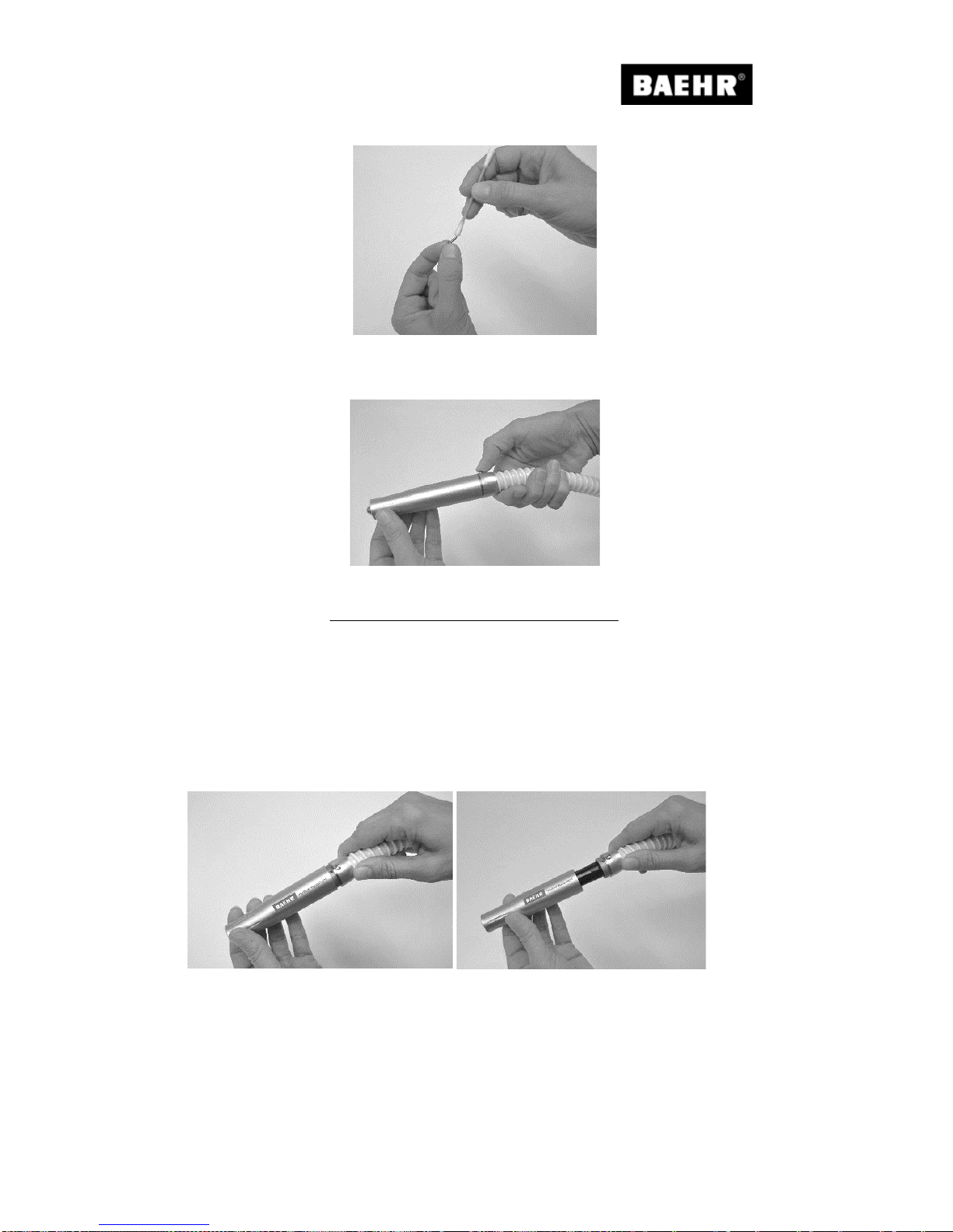
Operating Manual BaehrTec A1200 / A2000
English – V100 - Date 09/2017 Page 51/64
Fig. 29
Checker that the functioning is back to normal by pushing the button pusher with your finger.
Fig. 30
5.5.3 Changing the dampers for the handpiece case
If you notice that the h andpiece m ot or no l on ge r si ts com f o rt abl y in the handp iec e case, this
means that the dampers for the handpiece case are worn.
To change the dampers for the handpiece case, please proceed as follows:
Switch off your device at the main switch and disconnect the device from the mains.
Unscrew the handpi ec e cas e from the han dpiece cap.
Fig. 31 Fig. 32
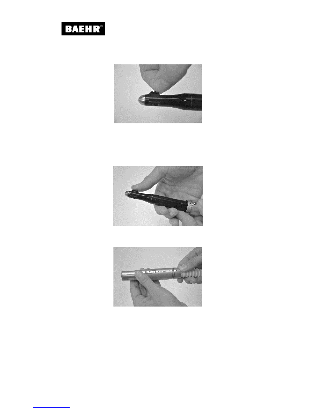
Operating Manual BaehrTec A1200 / A2000
Page 52/64 English – V100 - Date 09/2017
Take the nine dampers for the handpiece case from the slots on the handpiece motor (possibly
using a pair of tweezers) and dispose of these properly.
Fig. 33
Now reinsert t he new dampe rs for the handpi ece case. Make sure that you i nsert the t hree
black dampers in the middle row.
Insert the six green d amper s in the ou ter s tora ge ro ws. Press all of th e dam pers o nce again
afterwards.
Fig. 34
Now screw the handpiece case back onto the handpiece cap.
Fig. 35

Operating Manual BaehrTec A1200 / A2000
English – V100 - Date 09/2017 Page 53/64
5.5.4 Easy-Clean clamping mechanism
We are delighted to inform you that your handpiece contains our newly developed, innovative
and patented Easy-Clean clamping mechanism (hereinafter referred to as "Easy-Clean").
In a conventional clamping mechanism, the dirt that arises when working can cause an
instrument you a re o per at in g wi th yo u r han dpiece to sto p, eve n though the m o tor is running .
This can be accel e rat ed e ve n f ur th er b y cream s , oil s, fa t s o r the li k e. T he consequence: T h e
clamping mechanism is no longer functional or only functional to a limited extent and
previously ne ed ed to b e s e nt to the factory f or m ai nt en anc e and cleanin g. T o s ave yo u fr om
doing this in future, we have developed Easy-Clean. You can easily clean Easy-Clean yourself
without great expense or effort.
The Easy-Clean grips need to be cleaned at least once a month!
Recommendation: In the case of an average of 8 to 10 treatments per day, you should clean
the grips every 14 days with the tool supplied. If you additionally want to clean the grips every
day for hygiene reasons – as well as the device itself – please only use the clamping
mechanism cleaner 2 (brush) with alcohol.
It is essential that you read this section with the utmost care! It contains
important information on protecting yourself, others and the device from
damage! It must only be used by trained professionals.
Never perform cleaning work or change a filter on a device that is still connected
to the mains. Turn off the device at the main switch beforehand and disconnect
it from the power supply.
Caution – risk of injury! Never try to perform cleaning work on the
handpiec e while the handpiece m otor is runni ng. The han dpiece motor
must be switched off.
Only the appropriat e t oo l sh ou l d be us ed to cle an Easy-Clean. Other types and
fields of application are carried out at your own risk, and may conceal dangers.
No form of misappropriation is permitted.
Improper use may lead to damage to persons or objects.
The manufacturer cannot be held responsible for damages caused by improper
use, unqualifie d staff or i nco rr ect operating.
All warranty claims are void following improper use.
The clamping mechanism cleaner must only be used only for Easy-Clean
(developed for self cle aning). W ith conventi onal clampin g mechanism s which
are not intended for self cleaning, under no circumstances must the clamping
mechanism cleaner be used, as the clamping mechanism will immediately
suffer damage.
Clean the clampi ng device clean er 1 after each us e and make sure that it is
always in a perfect hygi enic co ndition before use.
We recommend a brush (Art-No. 34916) to clean the clamping mechanism
cleaner 1.
For hygiene reasons, please clean the clamping mechanism cleaner 2 after use
under running wate r and then wi th alc o hol.
The images ar e for ill ustrative purposes o nly. Subj ect to tec hnical an d optical
changes.
1x
Clamping device cleaner 1
Universal stainless steel
Art-No.: 40287
1x
Clamping device cleaner 2
(Cleaning brush for Easy-Clean)
Art-No.: 40269
To clean Easy-Clean, please proceed as follows:

Operating Manual BaehrTec A1200 / A2000
Page 54/64 English – V100 - Date 09/2017
1.
Turn off the devi ce at t he main swit ch and d isco nnect i t from the po wer su ppl y.
Never clean th e de vic e while the ha n dpiece motor i s s till running ! Risk of inj ury!
In addition, the clamping mechanism will suffer damage!
2. Put on a dis posable glove , or p ull a fi nger co t over t he t humb on the h and wit h which
you want to hold the handpiece while cleaning, and then hold the handpiece in this hand.
3. Now p ress on the top of the handpiece with your thumb. By holdi ng the tip with the
disposable glove/finger cot, you prevent the tip from turning while cleaning (see Fig. 36).
4. Insert t he clampin g mechanism cleane r 1 without p ressure as fa r as possibl e into t he
opening of your handpiece and turn the clamping mechanism cleaner 1, pressing slightly
to the left and right (see Fig. 37).
5. Now pull out the clamping mechanism cleaner 1 from the opening. Next, remove the dirt
from the grooves on the clamping mechanism cleaner 1 with a small brush. Repeat the
cleaning process until you cannot remove any more dirt.
6. After use, clean the clamping mechanism cleaner 1 with Baehr quick surface
disinfectant (Art -No. 11015).
7. Now r em ove any final impu rit ies w ith t h e clam ping mecha nism c le ane r 2 b y i n sert i ng it
as deep as possible into the opening on your handpiece and then turning to the left and
right (see Fig. 38).
8. Now pull out the clamping mechanism cleaner 2 from the opening.
9. Only clean the clamping mechanism cleaner 2 with water, then with Baehr quick surface
disinfectant (Art-No. 11015) and th en with Bae hr Alco hol (Ar t-No. 1103 2) to degrease
the tool.
Fig. 36 Fig. 37 Fig. 38
You can also clean Easy-Clean in the event that cream, fat, oil or the like gets into the
clamping mechanism.

Operating Manual BaehrTec A1200 / A2000
English – V100 - Date 09/2017 Page 55/64
To do so proceed a s f ollows.
1. Turn off the devic e at the main switch and disconnect it from the power
supply. Never c lean the device w hile the handpi ece motor is sti ll running!
Risk of injury! In addition, the clamping mechanism will suffer damage!
2. Moist en the clampin g mech anism cl eaner 2 with alcohol (Art-No. 11032) (never
use re-lubricati ng disinfectant or othe r greasy substances, as Easy-Clean may
otherwise cease to function properly).
3. Insert the clamping mechanism cleaner 2 into the opening of your ha nd piece and
turn it to the left and right.
4. Remove the clamping mechanism cleaner 2.
5. Now leave the handpiece to air for at least 3 minutes.
Your handpiece is no w once again ready for operat ion .
If your handpiece still does not function correctly in spite of these cleaning measures, or if you
have any questions about the cleaning process, please get in touch with us.
For detail ed video instruct ions on cleanin g the Easy-Clean
grips to supplement this information sheet, please go to
www.fusspflege.com/easy-clean.
To access the website directly, please scan the QR code with your
smartphone and an appropriate app.

Operating Manual BaehrTec A1200 / A2000
Page 56/64 English – V100 - Date 09/2017
5.5.5 Instrument changing aid (insertion and removal aid for very small
instruments)
To accompany your Easy-Clean clamping mec hanism, we have develope d an instrument
changing aid to m ake i t easie r for you t o chang e (rem ove an d ins ert) ve ry sm all ins trum ents
(instrument diameter approx. 1.5 mm – approx. 5.0 mm).
It is essential that you read this section with the utmost care! It contains
important information on protecting yourself, others and the device from
damage! It must only be used by trained professionals.
Never change an i nstrument on a devi ce that is still connec ted to the mains.
Turn off the d evice at the m ain switch beforehand an d disconnect i t from the
power supply.
Caution – risk of injury! Never try to change the instrument on the
handpiec e while the h andpiece mo tor is runni ng. The han dpiece motor
must be switched off.
Only the appropriate tool should be used to change the instrument. Other types
and fields of application are carried out at your own risk, and may conceal
dangers. No form of misappropriation is permitted.
Improper use may lead to damage to persons or objects.
The manufacturer cannot be held responsible for damages caused by improper
use, unqualifie d staff or i nco rr ect operating.
All warranty claims are void following improper use.
Clean the instrument changing aid after each use and make sure that it is
always in a perfect hygi enic co ndition before use.
For hygiene reasons, please clean the instrument changing aid after use under
running water and then with Baehr quick surface disinfectant (Art-No. 11015).
The images ar e for ill ustrative purposes onl y. Subje ct to tec hnical and optical
changes.

Operating Manual BaehrTec A1200 / A2000
English – V100 - Date 09/2017 Page 57/64
Inserting
Insert the instrument shaft in
the clamping mechanism on
the handpiece.
Fig. 39
Hold the instrument changing
aid horizontall y to the
handpiece.
Fig. 40
With the countersink on the
head of the instrument
changing aid, insert the
instrument in the handpiece
up to the stop.
Fig. 41

Operating Manual BaehrTec A1200 / A2000
Page 58/64 English – V100 - Date 09/2017
Pull out
Hold the instrument changing
aid horizontall y to the
handpiece.
Fig. 42
Position the instrument head
behind the notch on the
instrument changing aid.
Place your thumb ove r the notc h
on the instrument changing aid,
so that the instrument does not
drop when removing.
Fig. 43
Carefully remove the instrument
from the clamping mechanism
on the handpiece with the
instrument changing aid.
Fig. 44
For detailed video instructions on using the instrument
changing ai d to supplement this in formation sheet, pl ease
go to www.fusspflege.com/easy-clean.
To access the website directly, please scan the QR code with
your smartphone and an appropriate app.

Operating Manual BaehrTec A1200 / A2000
English – V100 - Date 09/2017 Page 59/64
6 Technical Data
BaehrTec A1200
Medical device
Class 2A according to EU Directive 93/42
Medical devices
EMC test
Under EN 60601-1
Operating voltage
110 – 240 V AC voltage
Frequency
50 – 60 Hz
Micromotor speed range
6,000 – 35,000 rpm adjustable
Accuracy of the speeds
6,000 – 10,000 rpm, tolerance +/- 25 %
10,001 – 20,000 rpm, tolerance +/- 20 %
20,001 – 35,000 rpm, tolerance +/- 10 %
Power consumption
Max. 150 W
Micromotor voltage
24 V
Working vol tage
28 V
Controller dimensions (W x D x H) in mm
(without handpiece outlet, without handpiece
button and
without filter cartridge)
220 x 195 x 110
Controller weight
Mix approx. 2,100 g
Handpiece dimensions (W x min. diameter x max.
diameter) in mm
~117 x ~19 x ~24
Handpiece weight
Mix approx. 99 g
Dust bag lid weight
Mix approx. 70 g
Ambient temperature (operation)
+10° - +35° C
Storage temperature
-5° - +40°C
Humidity
30% - 85 %
Permitted air pressure
800 hPa - 1060 hPa
Max. Vacuum (suction level 1) with filter and dust
bag
- 30 mbar +/- 25%
Max. Vacuum (suction level 1+) with filter and dust
bag
- 34 mbar +/- 25%
Max. Vacuum (suction level 2) with filter and dust
bag
- 38 mbar +/- 25%
Max. Vacuum (suction level 2+) with filter and dust
bag
- 42 mbar +/- 25%
Max. Vacuum (suction level 3) with filter and dust
bag
- 46 mbar +/- 25%
Max. Vacuum (suction level 3+) with filter and dust
bag
- 50 mbar +/- 25%
Max. Vacuum (suction level 4) with filter and dust
bag
- 54 mbar +/- 25%
Max. Vacuum (suction level 4+) with filter and dust
bag
- 58 mbar +/- 10%
Max. Vacuum (suction level 5) with filter and dust
bag
- 62 mbar +/- 10%
Max. Vacuum (suction level 5+) with filter and dust
bag
- 66 mbar +/- 10%
Max. Vacuum (suction level 6) with filter and dust
bag
- 70 mbar +/- 10%
Fuse
2X microfuse, 3.15 A delay (Type H)
IP Protection Class 30
Not protected against water
Protection against ingress of solid foreign
objects with a diameter > than 2.5 mm
Volume
Measurement conditions:
Device on foam pad (20 mm) from the front;
distance 1m; dust bag used; turbi ne protection fi lter
inserted; filter cartridge installed, handpiece
displaced 1m from the control unit and covered.
Extracted air flows freely, not discharging in the
direction of the sound-level measurement device.
Handpiece speed: 6,000 rpm
45 db to 53 db +/- 10%

Operating Manual BaehrTec A1200 / A2000
Page 60/64 English – V100 - Date 09/2017
BaehrTec A2000
Medical device
Class 2A according to EU Directive 93/42
Medical devices
EMC test
Under EN 60601-1
Operating voltage
110 – 240 V AC voltage
Frequency
50 – 60 Hz
Micromotor speed range
6,000 – 40,000 rpm adjustable
Accuracy of the speeds
6,000 – 10,000 rpm, tolerance +/- 25 %
10,001 – 20,000 rpm, tolerance +/- 20 %
20,001 – 40,000 rpm, tolerance +/- 10 %
Power consumption
Max. 150 W
Micromotor voltage
24 V
Working vol tage
28 V
Controller dimensions (W x D x H) in mm
(without handpiece outlet, without handpiece
button and
without filter cartridge)
220 x 195 x 110
Controller weight
Mix approx. 2,100 g
Handpiece dimensions (W x min. diameter x max.
diameter) in mm
~117 x ~19 x ~24
Handpiece weight
Mix approx. 99 g
Dust bag lid weight
Mix approx. 70 g
Ambient temperature (operation)
+10° - +35° C
Storage temperature
-5° - +40°C
Humidity
30% - 85 %
Permitted air pressure
800 hPa - 1060 hPa
Max. Vacuum (suction level 1) with filter and dust
bag
- 35 mbar +/- 25%
Max. Vacuum (suction level 1+) with filter and dust
bag
- 40 mbar +/- 25%
Max. Vacuum (suction level 2) with filter and dust
bag
- 55 mbar +/- 25%
Max. Vacuum (suction level 2+) with filter and dust
bag
- 62 mbar +/- 10%
Max. Vacuum (suction level 3) with filter and dust
bag
- 67 mbar +/- 10%
Max. Vacuum (suction level 3+) with filter and dust
bag
- 75 mbar +/- 10%
Max. Vacuum (suction level 4) with filter and dust
bag
- 80 mbar +/- 10%
Max. Vacuum (suction level 4+) with filter and dust
bag
- 85 mbar +/- 10%
Max. Vacuum (suction level 5) with filter and dust
bag
- 90 mbar +/- 10%
Max. Vacuum (suction level 5+) with filter and dust
bag
- 95 mbar +/- 10%
Max. Vacuum (suction level 6) with filter and dust
bag
- 100 mbar +/- 10%
Fuse
2X microfuse, 3.15 A delay (Type H)
IP Protection Class 30
Not protected against water
Protection against ingress of solid foreign
objects with a diameter > than 2.5 mm
Volume
Measurement conditions:
Device on foam pad (20 mm) from the front;
distance 1m; dust bag used; turbi ne protection fi lter
inserted; filter cartridge installed, handpiece
displaced 1m from the control unit and covered.
Extracted air flows freely, not discharging in the
direction of the sound-level measurement device.
Handpiece speed: 6,000 rpm
48 db to 55 db +/- 10%
Subject to visual and technical changes.

Operating Manual BaehrTec A1200 / A2000
English – V100 - Date 09/2017 Page 61/64
Guidelines and MANUFACTURER statemen t – ELECTROMAGNETIC EMISSION
The model BaehrTec A1200/A2000 is intended for use in the ELECTROMAGNETIC ENVIRONMENTS specified below. The
customer or end user
N11)
of the model BaehrTec A1200/A2000 should ensure it is used in such an environment.
Emission measurements
Compliance
ELECTROMAGNETIC ENVIRONMENT – Guidelines
HF emissions
according to CISPR 11
Group 1
The model BaehrTec A1200/A2000 uses HF energy exclusively
in its internal FUNCTION. That means that its HF emission is
very low and it is unlikely that adjacent elect ronic devices will
suffer any interference.
The model BaehrTec A1200/ A2000 is intended for use in all
facilities including livi ng areas and also that are connected to a
PUBLIC POWER SUPPLY that include buil dings that are used
for residential purposes.
HF emi ssions
according to CISPR 11
Class B
Harmonics
under IEC 61000-3-2
Class A
Voltage fluctuations/
flicker under IEC 61000-3-3
Fulfilled
N11)
National footnote: Here, user refers to a "RESPONSIBLE ORGANISATION".
Guidelines and MANUFACTURER DECLARATION – ELECTROMAGNETIC STABILITY
The model BaehrTec A1200/A2000 is intended for use in the ELECTROMAGNETIC ENVIRONMENTS specified below. The
customer or user
N13)
of the model BaehrTec A1200/A2000 should ensure t hat it is used in such an environment.
STABILITY
TESTS
IEC 60601-
TEST LEVEL
COMPLIANCE
LEVEL
ELECTROMAGNETIC
ENVIRONMENT –
GUIDELINES
ELECTROSTATIC
DISCHARGE (ESD)
under IEC 61000-4-2
± 6 kV
Contact discharge
± 8 kV
Air discharge
± 6 kV
Contact discharge
± 8 kV
Air discharge
Floorings should be made
of wood or concrete or
covered with tiles. If the
floor is covered with
synthetic material, the
relative humidity must be
at least 30 %.
Electrical
electric
disturbance variables/bursts
according to IEC 61000-4-4
± 2 kV
For power supply lines
± 1 kV
For input and
output lines
± 2 kV
For power supply lines
± 1 kV
For input and
output lines
The quality of the supply
voltage should be to the
standard
of a typical
commercial or hospital
environment.
Surge voltages
under IEC 61000-4-5
± 1 kV
Voltage phase
conductor phase conductor
± 2 kV
Voltage phase
conductor -
earth
± 1 kV
Voltage phase conductor phase conductor
± 2 kV
Voltage phase conductor earth
The quality of the supply
voltage should be to the
standard of a typical
commercial or hospital
environment.
Voltage dips,
Short interruptions
and fluctuations in the
supply voltage
according to IEC 61000-4-11
< 5 % U
T
for 1/2 period
(> 95% dip)
40 % U
T
for 5 periods
(60 % dip)
70 % U
T
for 25 periods
(30 % dip)
< 5 % U
T
for 5 s
(> 95% dip)
< 5 % U
T
for 1/2 period
(> 95% dip)
40 % U
T
for 5 periods
(60 % dip)
70 % U
T
for 25 periods
(30 % dip)
< 5 % U
T
for 5 s
(> 95% dip)
The quality of the supply
voltage should be to the
standard of a typical
commercial or hospital
environment.
We recommend powering
the model BaehrTec
A1200/A2000 with a
interruption-
free power
supply or a battery, should
the user of the model
BaehrTec A1200/A2000
FUNCTION also require
continued FUNCTION
also when interruptions in
the power supply occur.
Magnetic field at a supply
frequency of
(50/60 Hz)
under IEC 61000-4-8
3 A/m
3 A/m
The magnetic fields of
both power frequencies
should be to the standard
of a typical commercial or
hospital environment.
N13)
National footnote: Here, user refers to a "RESPONSIBLE ORGANISATION".

Operating Manual BaehrTec A1200 / A2000
Page 62/64 English – V100 - Date 09/2017
Guidelines and MANUFACTURER declarati on – ELECTROMAGNETIC STABILITY
The model BaehrTec A1200/ A2000 i s intended f or use in t he ELECT ROMAGNETIC ENVIRO NMENTS specifi ed bel ow.
The customer or user
N15)
of the model BaehrTec A1200/A2000 should ensure that it is used in such an environment.
STABILITY
tests
IEC 60601TEST LEVEL
COMPLIANCE
level
ELECTROMAGNETC
ENVIRONMENT – guidelines
Conducted HFdisturbances
according to IEC 610004-6
Radiated
HF disturbances under
IEC 61000-4-3
3 V
Effective value
150 kHz to 80
MHz
3 V/m
80 MHz to 2.5
GHz
3 V
Effective value
3 V/m
Portable and mobile radio sets are
not used closer to the model
BaehrTec A1200/A2000 including
lines than the recommended
protective distance, according to
the appropriate formula to calculate
the transmission frequency.
Recommended protective
distance:
d = 1.2
P
d = 1.2
P
80 MHz to 800 MHz
d = 2.3
P
800 MHz to 2.5 GHz
with P as the nominal output of the
transmitter in Watt (W) according to
the specifications provi ded by the
transmitter manuf acturer and d as
the recommended protective
distance in metres (m).
The field strength of stationary
radios is lower than the
CONFORMANCE LEVEL
b
at all
frequencies according to a test
conducted on location
a
.
Interference is possible in the
vicinity of devices marked with the
following symbols.
NOTE 1 At 80 MHz and 800 MHz, the higher value applies.
NOTE 2 These guidelines m ay not apply in all situati ons. The distribution of electromagnetic waves is affec ted by
absorption and reflecti ons fr om buildings, objects and people.
a
The field strengths of stationar y radios, such as basis stations of radio telephones and mobile land radio services
amateur stations, AM and FM radio and t elev ision channel s cannot be theor eti call y det ermined prec isel y befor ehand.
In order to
ascertain the ELECTROMAGNETI C ENVIRONMENT as a result of stationary HF transmitters, an investigation of the
location is recommended. If the determined field strength at the location of the model BaehrTec A1200/A2000 ex ceed
the
CONFORMANCE L
EVEL, the model BaehrTec A1200/A2000 must be monitored
regarding its normal operation at every location it is used. If any unusual features are observed, it may be necessary
to take additional measures, such as reorienting or relocating the model BaehrTec A1200/A2000.
b
The field strength is smaller than 3V/m across the frequency range of 150 kHz to 80 MHz.
N15)
National footnote: Here, user refers to a "RESPONSIBLE ORGANISATION".

Operating Manual BaehrTec A1200 / A2000
English – V100 - Date 09/2017 Page 63/64
Recommended protective distances between portable and mobile HF communication devices and the model
BaehrTec A1200/A2000
The BaehrTec A1200/A2000 model is intended for operation in an ELECTROMAGNETIC E NVIRONMENT in which radiated
HF disturbances are controlled. The customer or the user of the model BaehrTec A1200/A2000 can help prevent,
electromagnetic disturbanc es by observing the minimum distances between portabl e and mobile HF communication faciliti es
(transmitters) and the model BaehrTec A1200/A2000, as given below according to the maximum output of the communication
facilities
Nominal output
of the transmitter
W
Protective distance acco rding to transmitter frequency
m
150 kHz to 80 MHz
d = 1.2
P
80 MHz to 800 MHz
d = 1.2
P
800 MHz to 2.5 GHz
d = 2.3
P
0.01
0.12
0.12
0.23
0.1
0.38
0.38
0.73 1 1.2
1.2
2.3
10
3.8
3.8
7.3
100
12
12
23
The distance can be determined for transmitters whose nomi nal output is not given in the tabl e above using the formula that
belongs to the respective column, where P i s the nominal output of the transm itt er in Watt (W) according to the specif ic ation
provided by t he manufacturer.
NOTE 1 An additional fac tor of 10/3 was used to calcul ate the recommended protec tive distance from transm itters in the
frequency range 80 MHz to 2.5 GHz in order to lower the probability of a disturbance being caused by a mobile/portable device
unintentionally brought into the PATIENT area.
NOTE 2 These guidelines m ay not apply in all situations. The distr ibution of electromagneti c wav es i s affected by absorption
and reflections from buildings, objects and people.
7 Spare parts/accessories
• Baehr cloths
Art No.: 11000
• Baehr cloths refill bag
Art No.: 11001
• Baehr quick surface disinfectant
Art No.: 11015
• Baehr alcohol
Art No.: 11032
• Replacement filter set for A2000 (fits A1200/A2000)
Art No.: 22734
• Brushes
Art No.: 34916
• Easy-Clean tool kit for BaehrTec A2000 (fits A1200/A2000)
Art No.: 40285
• Damper for handpiece case (Set
Art No.: 40286
• Power cable case, short for BaehrTec A2000 (fits A1200/A2000)
Art No.: 40796
• Power cable with straight connector
Art No.: 20970006
• Foot controller for BaehrTec A2000
Art No.: 23000001

Operating Manual BaehrTec A1200 / A2000
Page 64/64 English – V100 - Date 09/2017
Contact address & manufacturer
Gustav Baehr GmbH
Max-Eyth-Str. 39
D-71332 Waiblingen
Tel.: 07151 95 90 20
Fax: +49 7151 1 84 44
www.baehrshop.de
 Loading...