

Page 1
Installation and Instruction
Manual
MODEL COIN
Flow Meters
Page 2
PRESO COIN LOCATION INSTRUCTIONS
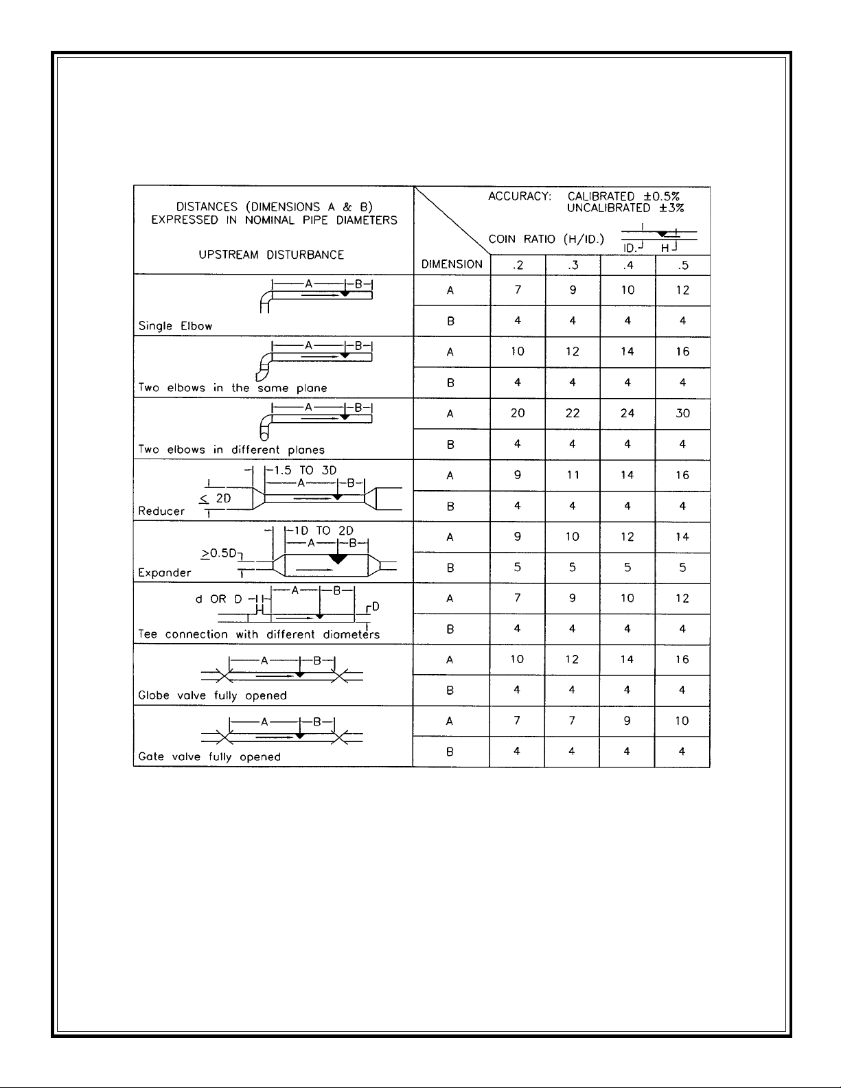
Straight pipe requirements: Accuracy is affected by the piping configurations due to
the disturbances of the flow profile. A fully developed symmetrical flow profile is
achieved with the minimum upstream and downstream recommended lengths.
NOTES:
1 - For upstream and downstream lengths equal to one half the values shown
add 1 percent to the accuracy value.
2 - Any flow conditioner shall be installed in the straight length between the
primary element and the upstream distance, or the fitting closest to the
element. The straight lengths between fitting and conditioner shall be at
least 10D and the length between conditioner and Coin Meter shall be at
least 15D.
3 - For other fittings, configurations, contact PRESO.
Page 3
STRAIGHT PIPE RUN REQUIREMENTS
As with most flow elements, proper operation and performance is dependent on
the required lengths of unrestricted upstream and downstream piping. The recommended minimum length of the upstream side of the COIN Flow Element depends on the type of fitting at the start of the straight run, and the pipe configuration. Minimum upstream and downstream lengths are shown in the location instructions on back page. The minimum lengths will cause a slight coefficient shift.
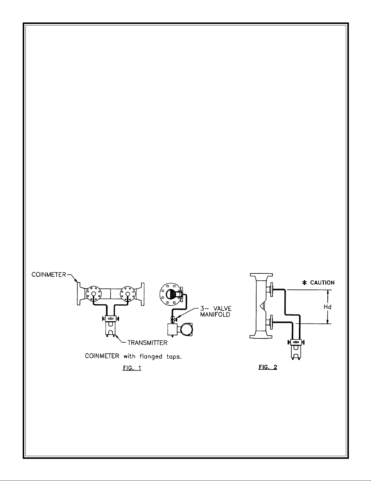
SELECTING A MOUNTING LOCATION
A horizontal installation is recommended for all COIN elements rotated 90° along
the pipe center line (Figure 1).
This method of mounting allows for free passage of solids and eliminates air entrapment at the transmitter connection. Other positions are acceptable provided
proper venting of the transmitter is accomplished and differences in lead line elevations are considered. Vertical installations as shown in Figure 2 may introduce
a slight hydrostatic head effect, which must be considered when zeroing the
transmitter. Connections between the COIN Meter and the transmitter should be
3/8” tubing minimum. The use of a 3-valve manifold is recommended for zeroing
the transmitter.
Before installation of any COIN element inspect for damage; particularly at sealing surfaces. Any damage should be reported to Preso Meters as soon as possible. Each flow element has an arrow indicating the required direction of flow.
Failure to properly orient the COIN element may cause improper results when
using data supplied for an element that has been calibrated.
Page 4

TYPICAL HORIZONTAL INSTALLATION FOR LIQUID
TYPICAL HORIZONTAL INSTALLATION FOR GAS
TYPICAL HORIZONTAL INSTALLATION FOR STEAM
Page 5

TYPICAL VERTICAL INSTALLATION FOR LIQUID
TYPICAL VERTICAL INSTALLATION FOR GAS
TYPICAL VERTICAL INSTALLATION FOR STEAM
Page 6

WARNING:
Never exceed the maximum pressure or temperature recommended for the
measured process. Exceeding proper pressure or temperature ratings can
lead to personal injury or equipment damage. The process piping flanges
should be identical to those on the COIN meter. The process temperature
and pressure should never exceed that for which the element was designed.
LINE INSTALLATION
All flanged COIN flow elements require a gasket between the process line connection and the mating flange. Ensure the gaskets selected match the the size
and rating of the COIN meter and the line flanges. Gasket material must be selected to resist corrosive attack of the process.
Before completing the bolting process, be sure that the gaskets are properly
centered so that protrusion into the pipe opening is minimized. Misalignment
may cause added flow turbulence, however performance affects are typically
minimal depending upon the application. Bolt the element in line with suitable
hardware using recommended bolt torques for the type and class rating of the
flanges.
Torque all models per ANSI flange ratings.
Tighten the flange bolts in a progressive “star” pattern to avoid localized stresses
on the gaskets.
DO NOT EXCEED SPECIFIED TORQUE!
DIFFERENTIAL PRESSURE CONNECTIONS
The high pressure connection is always on the upstream side of the flow direction arrow and the Iow pressure connection on the downstream side. Fittings
used must be able to withstand the process temperature and pressure conditions as well as provide proper corrosion resistance. Preso offers three types of
fittings (See next page). Refer to the appropriate transmitter manual for connections to the transmitter high and Iow ports.
Page 7

When installing chemical tee seals tighten cap screws uniformly in a “star” pattern
to avoid localized stresses on the gaskets.
The ANSI flanged taps seals require a backup flange rated for the same type
and class as that on the COIN element. Backup flanges with bolts and nuts are
generally offered as an option to the transmitter and are not supplied with the
COIN element. Again, observe recommended torque specifications for the type
and class being used.
TYPICAL PRESSURE PORT CONFIGURATIONS
NPT TAPS
FLANGE TAPS
CHEM TEE TAPS
Page 8

PRESO
Flow Metering Equipment
A Division of Racine Federated Inc.
Limited Warranty and Disclaimer
PRESO Flow Metering Equipment, a division of Racine Federated Inc. warrants to
the end purchaser, for a period of one year from the date of shipment from our
factory, that all flow meters manufactured by it are free from defects in materials
and workmanship. This warranty does not cover products that have been damaged due to abnormal use, misapplication, abuse, lack of maintenance, modified
or improper installation. PRESO’s obligation under this warranty is limited to the
repair or replacement of a defective product, at no charge to the end purchaser, if
the product is inspected by PRESO and found to be defective. Repair or replacement is at PRESO’s discretion. A return goods authorization (RGA) number must
be obtained from PRESO before any product may be returned for warranty repair
or replacement. The product must be thoroughly cleaned and any process chemicals removed before it will be accepted for return.
The purchaser must determine the applicability of the product for its desired use
and assumes all risks in connection therewith. PRESO assumes no responsibility
or liability for any omissions or errors in connection with the use of its products.
PRESO will under no circumstances be liable for any incidental, consequential,
contingent or special damages or loss to any person or property arising out of the
failure of any product, component or accessory.
All expressed or implied warranties, including the implied warranty of merchant-
ability and the implied warranty of fitness for a particular purpose or application are expressly disclaimed and shall not apply to any products sold or
services rendered by PRESO.
The above warranty supersedes and is in lieu of all other warranties, either expressed or implied and all other obligations or liabilities. No agent or representative has any authority to alter the terms of this warranty in any way.
8635 Washington Ave., • Racine, WI 53406
Tel.: (262) 639-6770 • Fax: (262) 639-2267
Toll Free: (800) 632-7337
www.preso.com • info@preso.com
COIN INSTRUCTIONS 05-16-2003
 Loading...