

Page 1
Flow Instrumentation
PFB Round Fire Pump System
2000
1500
1000
2500
3000
GPM
M
F
APPROVED
PFA-XXX
X inch
250 SWP
X/XX
S/N AXXXXXXX
3500
4000
PTT-UM-00510-EN-02 (April 2014)
User Manual
Page 2
Flow Instrumentation, PFB Round Fire Pump System
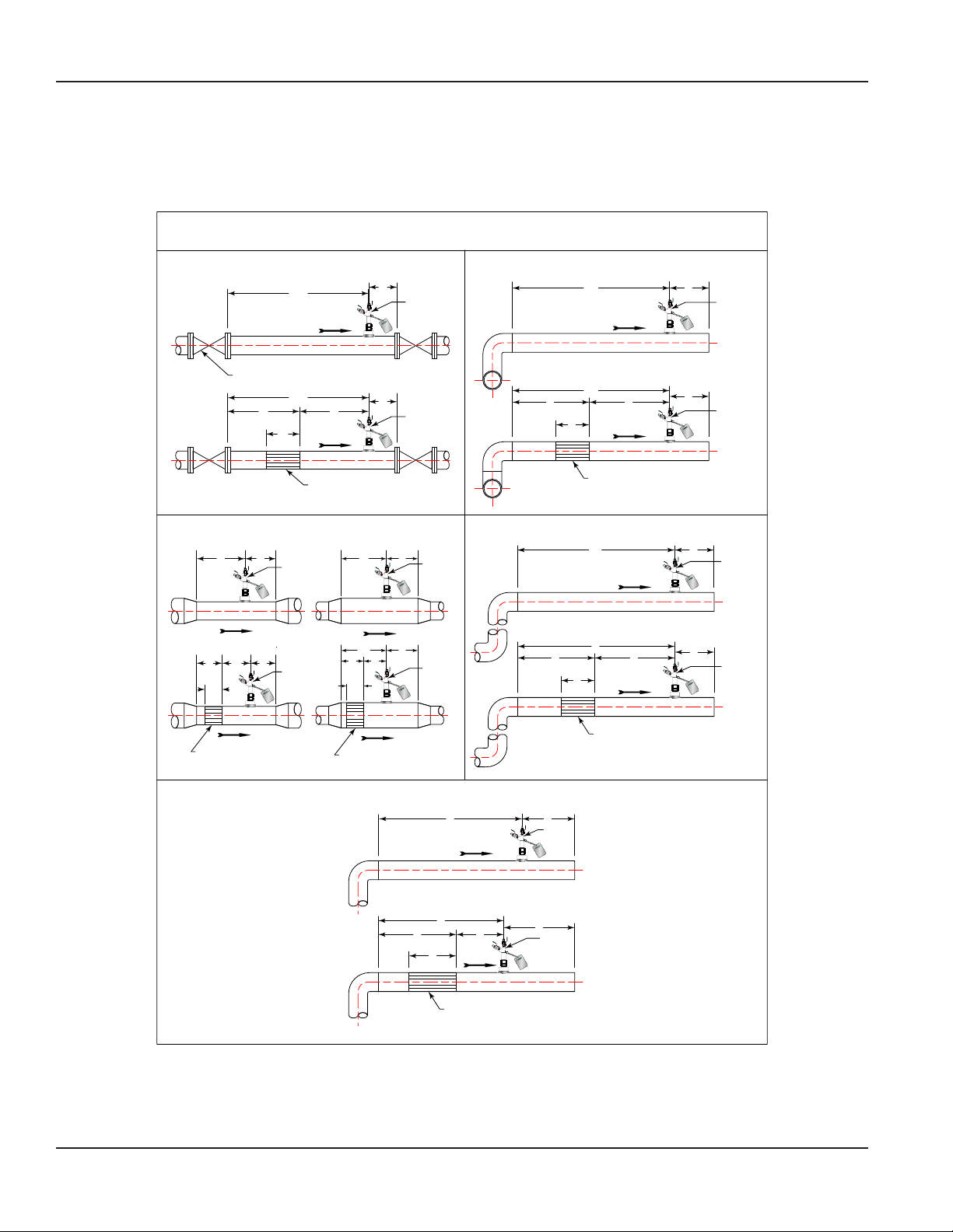
LOCATION INSTRUCTIONS
Straight pipe requirements: Accuracy is affected by the piping configurations due to the disturbances of the flow profile. A
fully developed symmetrical flow profile is achieved with the minimum upstream and downstream recommended lengths.
DISTANCES ARE EXPRESSED IN
NUMBER OF NOMINAL PIPE DIAMETERS
THROTTLED VALVE OR REGULATOR
27
FLOW
Regulator or
Partially Closed
Valve
11
6
2
5
FLOW
4
Preso
FLOW METERS
DEBITMETERS
MEDIDOR DE FLUJO
4
Preso
FLOW METERS
DEBITMETERS
MEDIDOR DE FLUJO
TWO ELBOWS IN DIFFERENT PLANES
FLOW
10
5
2
5
FLOW
424
Preso
FLOW METERS
DEBITMETERS
MEDIDOR DE FLUJO
4
Preso
FLOW METERS
DEBITMETERS
MEDIDOR DE FLUJO
CHANGE IN PIPE SIZE
49
FLOW METERS
DEBITMETERS
MEDIDOR DE FLUJO
FLOW
FLOW
4
FLOW METERS
DEBITMETERS
MEDIDOR DE FLUJO
4 6
6
Straightening Vane
Preso
Preso
Straightening
Vane
2
Straightening Vane
Straightening Vane
TWO ELBOWS IN THE SAME PLANE
49
Preso
FLOW METERS
DEBITMETERS
MEDIDOR DE FLUJO
FLOW
4
10
64
FLOW
Preso
FLOW METERS
DEBITMETERS
MEDIDOR DE FLUJO
4
2
FLOW
9
5
FLOW
Straightening Vane
311
Preso
FLOW METERS
DEBITMETERS
MEDIDOR DE FLUJO
3
Preso
FLOW METERS
DEBITMETERS
MEDIDOR DE FLUJO
A SINGLE ELBOW
7
FLOW
5
3
2
2
FLOW
3
Preso
FLOW METERS
DEBITMETERS
MEDIDOR DE FLUJO
3
Preso
FLOW METERS
DEBITMETERS
MEDIDOR DE FLUJO
Straightening Vane
Page 2 April 2014
Page 3

User Manual
INSTALLATION INSTRUCTIONS
• The primary station can be installed in any position on vertical or horizontal lines. However for best results on horizontal
liquid lines where the risk of air/gas entrapment in the water tubing is prevalent, install element with the head under the
horizontal center line.
• The Preso primary element is bidirectional. However, make sure head is parallel to the pipe run.
• For pipes measuring 1-1/4" primary element, MNPT and may be installed in any direction.
1. For pipes 2…6":
a. For pipes measuring 2…4", drill a 3/4" hole into the pipe. For 5…6", drill a 5/8" hole into the pipe.
b. Weld the coupling to the pipe in line with the hole.
c. Pass the probe through the packing gland and insert it into the pipe through the coupling. Tighten the hex nut to
the coupling.
d. Push the probe until it touches the opposite side of the pipe and tighten the hex nut of the packing gland.
2. For pipes 8…16":
a. For pipes measuring 8…10", drill a 1/2" hole on the side where a reading will be taken and a 13/32" hole on the other
side. For 12" pipes, drill a 5/8" hole on the side where a reading will be taken and 17/32" hole on the other side. For
14"…16" pipes, drill a 7/8" hole on the side where a reading will be taken and 25/32" hole on other side.
b. Weld the coupling to the pipe in line with the hole, making sure it is in line with the opposite hole.
c. Pass the probe through the packing gland and insert it into the pipe through the coupling. Tighten the hex nut to
the coupling.
d. Push the probe through the pipe until it passes through the opposite hole to ensure alignment.
e. Withdraw the probe and weld the other coupling to the pipe.
f. Push the probe through the packing gland until it enters the other hole and is flush with the outside wall of the pipe.
Tighten the hex nut of the packing gland.
g. Install the pipe to the coupling.
PFB - USUAL PFB - OTHER
LEGEND:
1. PRESO Primary Element - Annular
2. PRESO GMD Meter
3. Tubing or piping by others
4. Shut-o, equalizing valves and/or manifolds by others
Discharge
Optional to
Pump Inlet
Supply
Air Vent
Typical Piping Conguration
5. Condensation or separation chamber by others
Throttle Valve
Pipe Diameters from Valve
Fire Pump
Preso
PFB
System Bypass
(7)(3)
5
Valve
System ValveValve
Page 3 April 2014
Page 4

Control. Manage. Optimize.
PRESO is a registered trademark of Badger Meter, Inc. Other trademarks appearing in this document are the property of their respective entities. Due to continuous research,
product improvements and enhancements, Badger Meter reserves the right to change product or system specications without notice, except to the extent an outstanding
contractual obligation exists. © 2014 Badger Meter, Inc. All rights reserved.
www.badgermeter.com
The Americas | Badger Meter | 4545 West Brown Deer Rd | PO Box 245036 | Milwaukee, WI 53224-9536 | 800-876-3837 | 414-355-0400
México | Badger Meter de las Americas, S.A. de C.V. | Pedro Luis Ogazón N°32 | Esq. Angelina N°24 | Colonia Guadalupe Inn | CP 01050 | México, DF | México | +52-55-5662-0882
Europe, Middle East and Africa | Badger Meter Europa GmbH | Nurtinger Str 76 | 72639 Neuen | Germany | +49-7025-9208-0
Europe, Middle East Branch Oce | Badger Meter Europe | PO Box 341442 | Dubai Silicon Oasis, Head Quarter Building, Wing C, Oce #C209 | Dubai / UAE | +971-4-371 2503
Czech Republic | Badger Meter Czech Republic s.r.o. | Maříkova 2082/26 | 621 00 Brno, Czech Republic | +420-5-41420411
Slovakia | Badger Meter Slovakia s.r.o. | Racianska 109/B | 831 02 Bratislava, Slovakia | +421-2-44 63 83 01
Asia Pacic | Badger Meter | 80 Marine Parade Rd | 21-04 Parkway Parade | Singapore 449269 | +65-63464836
China | Badger Meter | 7-1202 | 99 Hangzhong Road | Minhang District | Shanghai | China 201101 | +86-21-5763 5412 Legacy Document Number: 10-PTT-UM-00341
 Loading...