

Page 1
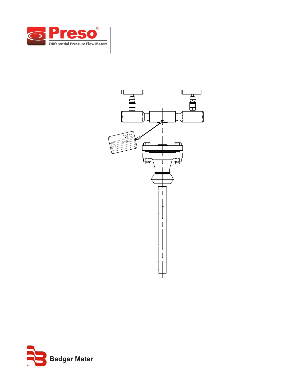
Ellipse® Pitot Tube Meter
AF Annular Flanged Meter
PTT-UM-00525-EN-02 (April 2014)
User Manual
Page 2

Ellipse® Pitot Tube Meter, AF Annular Flanged Meter
CONTENTS
Introduction. . . . . . . . . . . . . . . . . . . . . . . . . . . . . . . . . . . . . . . . . . . . . . . . . . . . . . . . . . . . . . . . . . . . . . . . . 3
Specications . . . . . . . . . . . . . . . . . . . . . . . . . . . . . . . . . . . . . . . . . . . . . . . . . . . . . . . . . . . . . . . . . . . . . . . . 3
Pipe Orientation and Sensor Mounting . . . . . . . . . . . . . . . . . . . . . . . . . . . . . . . . . . . . . . . . . . . . . . . . . . . . . . . 4
Installation Instructions, Single Support . . . . . . . . . . . . . . . . . . . . . . . . . . . . . . . . . . . . . . . . . . . . . . . . . . . . . . . 5
Installation Instructions, Double Support . . . . . . . . . . . . . . . . . . . . . . . . . . . . . . . . . . . . . . . . . . . . . . . . . . . . . . 6
Installation Drawings . . . . . . . . . . . . . . . . . . . . . . . . . . . . . . . . . . . . . . . . . . . . . . . . . . . . . . . . . . . . . . . . . . . 7
Location Instructions . . . . . . . . . . . . . . . . . . . . . . . . . . . . . . . . . . . . . . . . . . . . . . . . . . . . . . . . . . . . . . . . . . . 9
Flow Curve . . . . . . . . . . . . . . . . . . . . . . . . . . . . . . . . . . . . . . . . . . . . . . . . . . . . . . . . . . . . . . . . . . . . . . . . 10
Page ii April 2014
Page 3
INTRODUCTION
The Preso patented elliptical design outperforms and provides greater
accuracy than traditional differential pressure flow measurement devices. This
differential pressure flow meter is designed with a series of ports facing the
upstream velocity pressures, as well as flow sensing ports strategically located
ahead of the trailing edge flow separation.
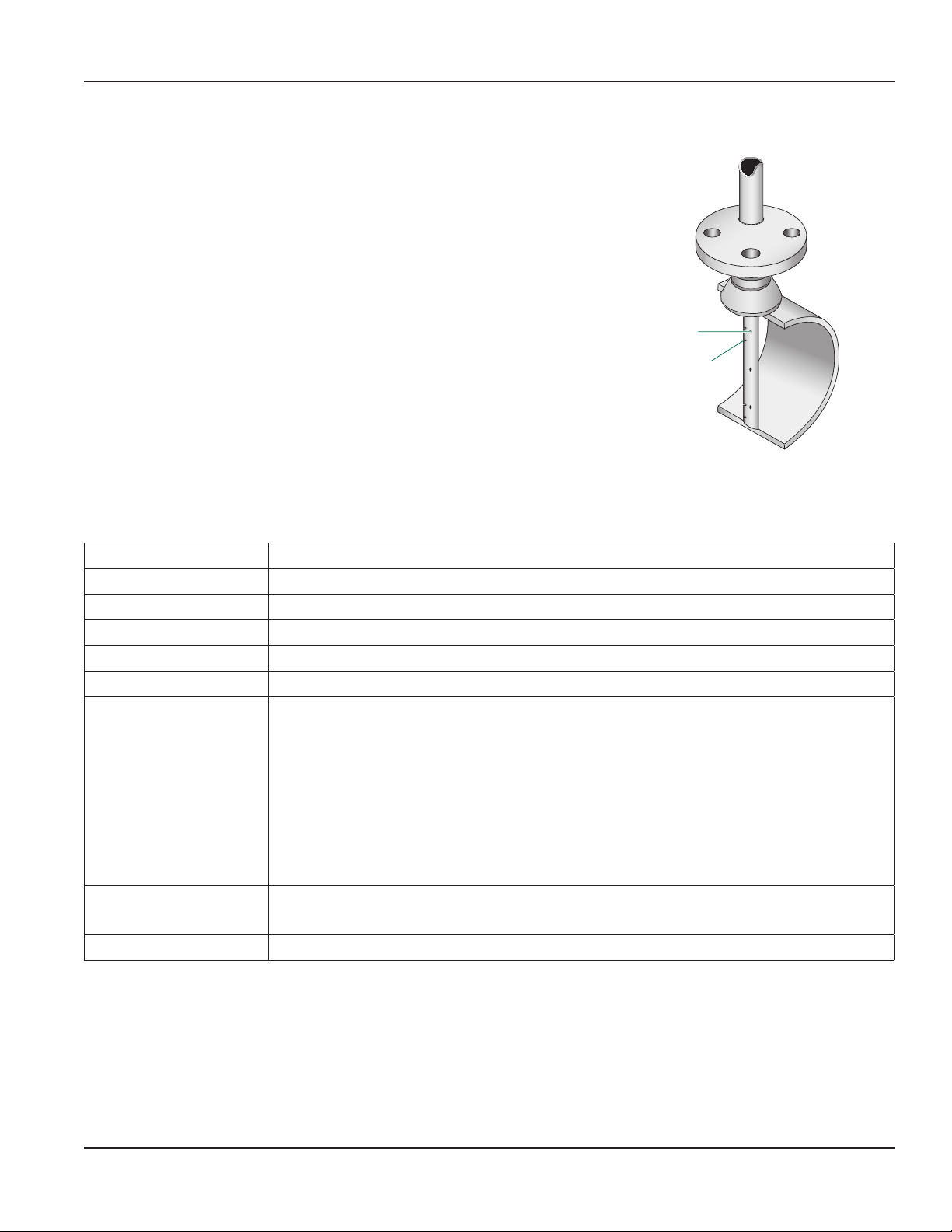
The multi-ported, self-averaging flow element consists of an elliptical shape
with two independent flow sensing chambers. The impact velocity sensing
holes (high pressure) are located along the leading edge and the true static
sensing holes (low pressure) are on the exterior probe side. Model AF comes
with instrument shutoff valves with provisions to accept a transmitter or direct
indicating meter.
User Manual
True static
sensing holes
Impact velocity
sensing holes
SPECIFICATIONS
Applications Air, liquids and gases
Pipe Sizes 2…72 inches (50…1820 mm)
Pressure Vary per flange ratings
Temperature Vary per flange ratings
Accuracy ±0.75% of reading
Turndown Ratio 17:1 with no vacuum effect
Standard Components T-type head, 316 SS 1/4" or 1/2" FNPT connection
CS 3000 lb weld fitting, ASTM A105
316/316L SS Ellipse sensor
Instrument valves (2 per sensor), 1/2", CS
316 SS ID tag with wire
150 lb 316/316L SS sensor flange
CS gasket with SS spiral wound ring
CS mounting flange, 150 lb ASTM A-105 with nuts and bolts
Reynolds Number Greater than 75,000 maintains most accurate flow measurements
Less than 75,000 consult factory for estimated results
Resonance If greater than 0.8, use double support per ASME PTC 19.3
Table 1: Specifications
Page 3 April 2014
Page 4
Ellipse® Pitot Tube Meter, AF Annular Flanged Meter
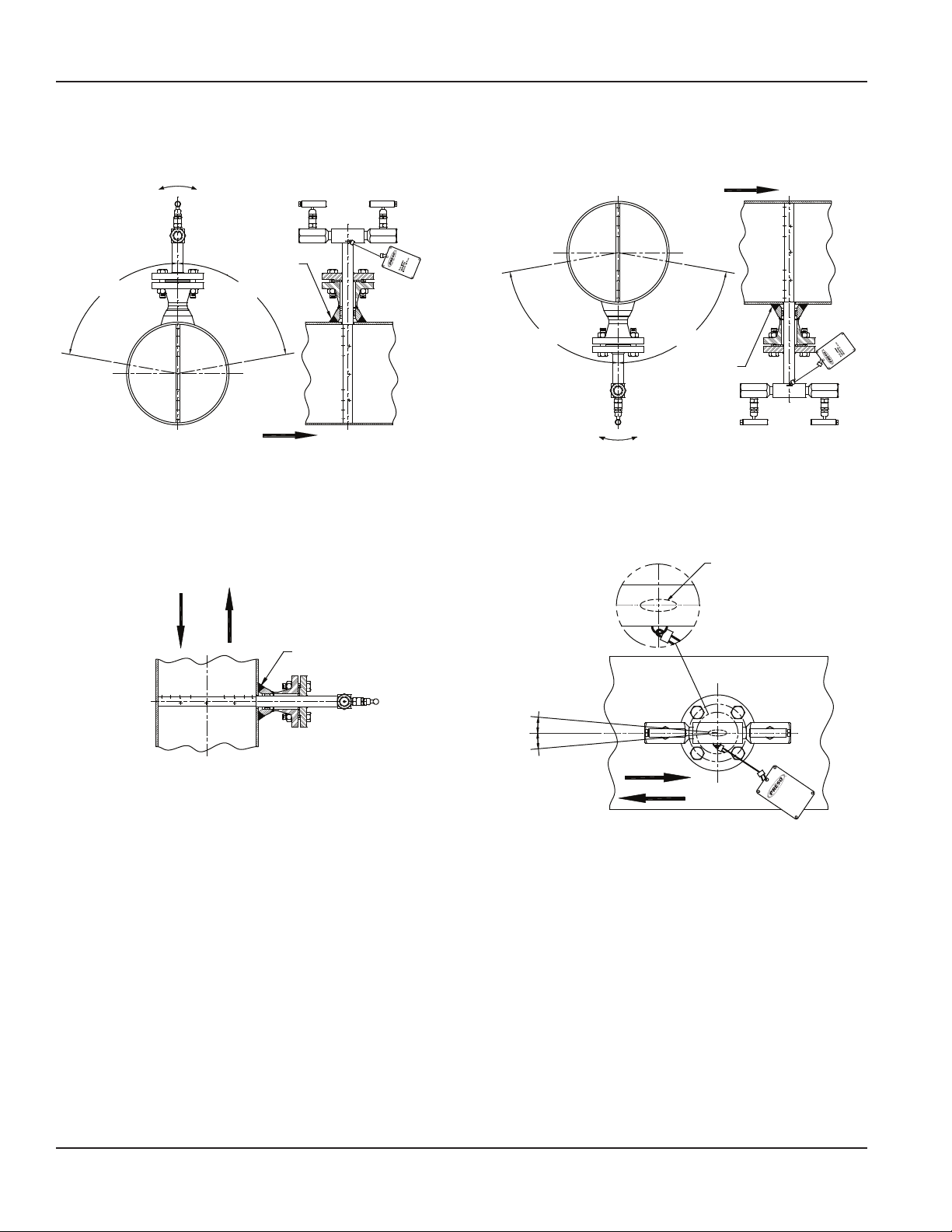
PIPE ORIENTATION AND SENSOR MOUNTING
Flow
80°
Field Weld
80°
Flow
Air and Gas
Flow
H
Field Weld
L
80°
Figure 1: Horizontal pipe installation
80°
Field Weld
H
Liquid
Ellipse
L
OTE:N Illustration represents installation for downward flow.
Figure 2: Vertical pipe installation Figure 3: Probe alignment
5° MAX
5° MAX
Flow
Flow Meters
Page 4 April 2014
Page 5

User Manual
INSTALLATION INSTRUCTIONS, SINGLE SUPPORT
1. Choose the proper location to install the AF Ellipse using AGA/ASME standards (or equivalent). See “Location Instructions”
on page 9.
2. Grind the surface of the pipe where the AF Ellipse is to be inserted to provide a clean area for welding.
3. Drill a hole through the pipe wall according to Table 2.
Model / Sensor Weld Connector Drill Bit
AF0 (1/2") 3/4" 5/8"
AF (7/8") 1-1/4" 1-1/8"
AF1 (1-1/4") 1-1/2" 1-3/8"
AF2 (2-1/4") 3" 2-3/4"
Table 2: Single support drill bit size
4. Deburr the hole just drilled, especially on the inside of the pipe.
5. Weld the mounting hardware assembly to the pipe, centered on the drilled hole, using standard codes for your
application (1/16" weld gap recommended). Align low point of radius on bottom of weld-o-let so that it is in line with the
pipe centerline.
Low Point
Horizontal
Low Point
of Radius
Pipe
Centerline
Pipe
Centerline
Figure 4: Weld alignment
Vertical
of Radius
Low Point
of Radius
L
H
6. Install the gasket and place the AF Ellipse sensor into the pipe.
7. While holding the AF Ellipse in its fully inserted position, align the arrow on the sensor head with the direction of ow. See
Figure 5.
H
Field Weld
L
5° MAX
Ellipse
Flow
5° MAX
Figure 5: Sensor alignment
Flow
Flow Meters
8. Thoroughly tighten all of the bolts on the ange and assemble all the parts that make the instrument head.
Page 5 April 2014
Page 6

Ellipse® Pitot Tube Meter, AF Annular Flanged Meter
9. Install the instrument valves (optional) at the AF Ellipse head connections. Make sure the valves are FULLY CLOSED to
prevent them from leaking during startup.
INSTALLATION INSTRUCTIONS, DOUBLE SUPPORT
1. Follow steps 1 through 5 in “Installation Instructions, Single Support”. At 180° from and on the same plane as the
previously drilled hole, grind the surface of the pipe to provide a clean area for welding. Drill a hole and deburr, especially
on the inside of the pipe. The hole used for the double support should be sized according to Table 3.
Model / Sensor Weld Connector Drill Bit
AF (7/8") 1/2" 1/2"
AF1 (1-1/4") 1" 7/8"
AF2 (2-1/4") 3" 2-3/4"
Table 3: Double support drill bit size
2. Weld the double support weld-o-let or thread-o-let making sure that it is centered with the drilled hole and the low point
on the bottom of the weld-o-let or thread-o-let is in line with the pipe centerline (1/16" weld gap recommended).
3. Install the AF Ellipse sensor through the two holes. Make sure that the double support pin passes through the guide ring.
See Figure 6.
Models AF & AF1
Guide
Ring
Plug
Ellipse Sensor
Thread-o-let
Double Support
Pin
Figure 6: Double support pin
Guide
Ring
Cap
Model AF2
Ellipse Sensor
Weld-o-let
Double Support
Pin
4. Align the arrow located on the sensor head in the direction of ow as in step 7, “Installation Instructions, Single Support” on
page 5.
5. Install and tighten all nuts and bolts (provided). Bolt torques should be in accordance with applicable standards.
6. Install the plug into the end of the double support thread-o-let* (weld on cap for AF2). Tighten the plug to
prevent leakage.
OTE:N * Use a thread sealant suitable for the process when making this connection.
Page 6 April 2014
Page 7

INSTALLATION DRAWINGS
User Manual
Flow
Up to
80°
Up to
80°
3-Valve Manifold
DP Transmitter or
Direct Read Gage
Side View
Figure 7: Typical horizontal installation for liquid applications
DP Transmitter or
Direct Read Gage
H L
Front View
Up to
80°
H L
Up to
80°
Flow
Side View
Figure 8: Typical horizontal installation for air and gas applications
Front View
3-Valve Manifold
Page 7 April 2014
Page 8

Ellipse® Pitot Tube Meter, AF Annular Flanged Meter
Flow
3-Valve Manifold
DP Transmitter or
Direct Read Gage
Side View
Figure 9: Typical vertical installation for liquid applications
DP Transmitter or
Direct Read Gage
3-Valve Manifold
Front View
Flow
Side View
Figure 10: Typical vertical installation for air and gas applications
Front View
Page 8 April 2014
Page 9

User Manual
LOCATION INSTRUCTIONS
Straight pipe requirements: Accuracy is affected by the piping configurations due to the disturbances of the flow profile. A
fully developed symmetrical flow profile is achieved with the minimum upstream and downstream recommended lengths.
DISTANCES ARE EXPRESSED IN
NUMBER OF NOMINAL PIPE DIAMETERS
THROTTLED VALVE OR REGULATOR TWO ELBOWS IN DIFFERENT PLANES
CHANGE IN PIPE SIZE TWO ELBOWS IN THE SAME PLANE
A SINGLE ELBOW
Figure 11: Location instructions
Page 9 April 2014
Page 10

ANNULAR ELLIPS
1
.9
.6
.5
.4
.3
Ellipse® Pitot Tube Meter, AF Annular Flanged Meter
FLOW CURVE
12" 16" 20"
2 3 4 5 6 7 8 9 1
0
0
0
0
WATER 60° F
2 3 4 5 6 78 9 1
0
0
0
0
0
E
2" 2.5" 3.5"3" 4" 5" 6" 8" 10" 14" 18" 24" 30"
100
90
80
70
60
50
40
30
20
O
2
10
9
8
7
6
5
4
3
Figure 12: Flow curve
2 3 4 5 6 7 8 9 1
0
0
0
USGPM
2 3 4 5 6 78 9 1
0
0
0
2
∆P – INCHES OF H
.8
.7
.2
2 3 4 5 6 78 9 1
NOTE:
2" THRU 10" CURVES ARE FOR SCH. 40 PIPE
12" AND ABOVE ARE FOR SCH. STD. PIPE
1
Page 10 April 2014
Page 11

INTENTIONAL BLANK PAGE
User Manual
Page 11 April 2014
Page 12

Control. Manage. Optimize.
PRESO is a registered trademark of Badger Meter, Inc. Other trademarks appearing in this document are the property of their respective entities. Due to continuous research,
product improvements and enhancements, Badger Meter reserves the right to change product or system specications without notice, except to the extent an outstanding
contractual obligation exists. © 2014 Badger Meter, Inc. All rights reserved.
www.badgermeter.com
The Americas | Badger Meter | 4545 West Brown Deer Rd | PO Box 245036 | Milwaukee, WI 53224-9536 | 800-876-3837 | 414-355-0400
México | Badger Meter de las Americas, S.A. de C.V. | Pedro Luis Ogazón N°32 | Esq. Angelina N°24 | Colonia Guadalupe Inn | CP 01050 | México, DF | México | +52-55-5662-0882
Europe, Middle East and Africa | Badger Meter Europa GmbH | Nurtinger Str 76 | 72639 Neuen | Germany | +49-7025-9208-0
Europe, Middle East Branch Oce | Badger Meter Europe | PO Box 341442 | Dubai Silicon Oasis, Head Quarter Building, Wing C, Oce #C209 | Dubai / UAE | +971-4-371 2503
Czech Republic | Badger Meter Czech Republic s.r.o. | Maříkova 2082/26 | 621 00 Brno, Czech Republic | +420-5-41420411
Slovakia | Badger Meter Slovakia s.r.o. | Racianska 109/B | 831 02 Bratislava, Slovakia | +421-2-44 63 83 01
Asia Pacic | Badger Meter | 80 Marine Parade Rd | 21-04 Parkway Parade | Singapore 449269 | +65-63464836
China | Badger Meter | 7-1202 | 99 Hangzhong Road | Minhang District | Shanghai | China 201101 | +86-21-5763 5412 Legacy Document Number: 10-PTT-UM-00325
 Loading...