

Page 1
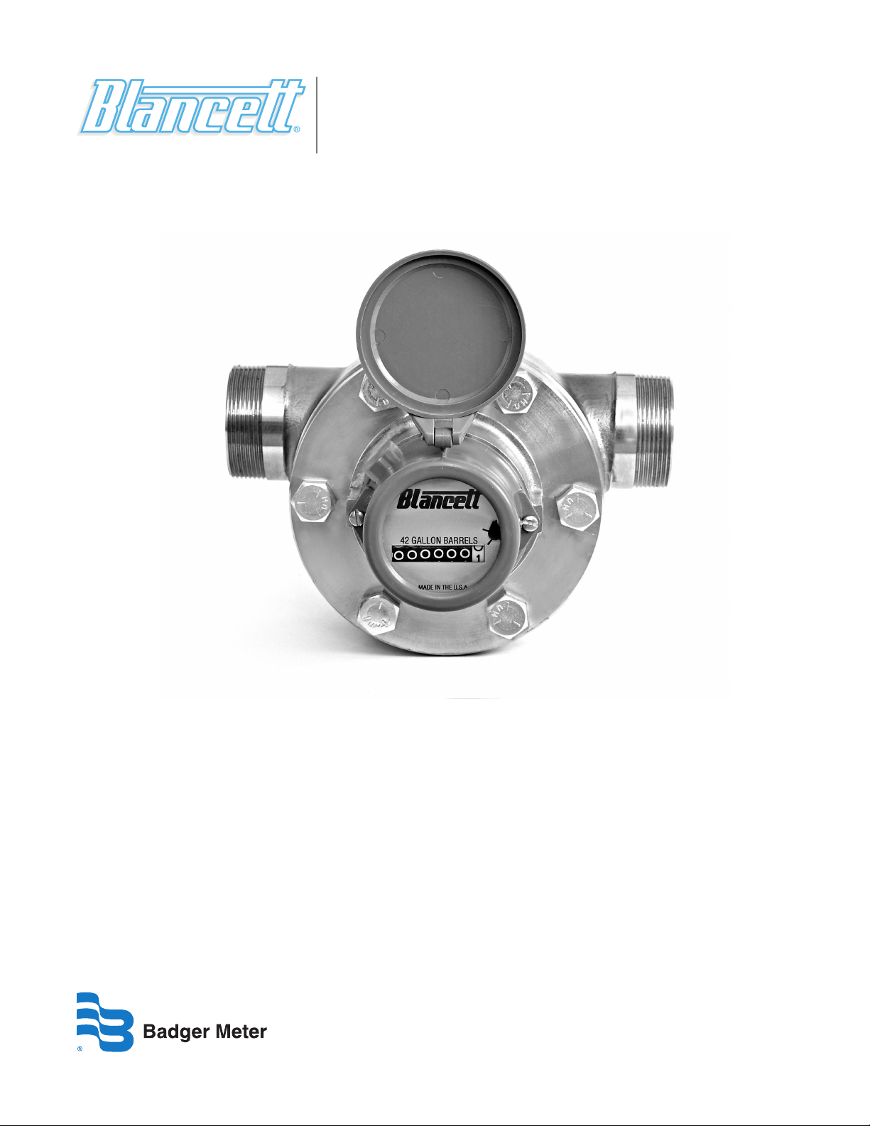
Positive Displacement Flow Meter
900 Series Positive Displacement Water Flood Meters
PDM-UM-00275-EN-01 (September 2013)
User Manual
Page 2

900 Series Positive Displacement Water Flood Meters
Page ii September 2013
Page 3

User Manual
CONTENTS
INTRODUCTION . . . . . . . . . . . . . . . . . . . . . . . . . . . . . . . . . . . . . . . . . . . . . . . . . . . . . . . . . . . . . . . . . . . . . . 5
OPERATING PRINCIPLE. . . . . . . . . . . . . . . . . . . . . . . . . . . . . . . . . . . . . . . . . . . . . . . . . . . . . . . . . . . . . . . . . . 5
SPECIFICATIONS. . . . . . . . . . . . . . . . . . . . . . . . . . . . . . . . . . . . . . . . . . . . . . . . . . . . . . . . . . . . . . . . . . . . . . 5
INSTALLATION INSTRUCTIONS . . . . . . . . . . . . . . . . . . . . . . . . . . . . . . . . . . . . . . . . . . . . . . . . . . . . . . . . . . . . 6
OPERATIONAL STARTUP. . . . . . . . . . . . . . . . . . . . . . . . . . . . . . . . . . . . . . . . . . . . . . . . . . . . . . . . . . . . . . . . . 7
DIMENSIONS . . . . . . . . . . . . . . . . . . . . . . . . . . . . . . . . . . . . . . . . . . . . . . . . . . . . . . . . . . . . . . . . . . . . . . . . 7
TROUBLESHOOTING GUIDE . . . . . . . . . . . . . . . . . . . . . . . . . . . . . . . . . . . . . . . . . . . . . . . . . . . . . . . . . . . . . . 8
REPAIR KIT INFORMATION . . . . . . . . . . . . . . . . . . . . . . . . . . . . . . . . . . . . . . . . . . . . . . . . . . . . . . . . . . . . . . . 8
Page iii September 2013
Page 4

900 Series Positive Displacement Water Flood Meters
Page iv September 2013
Page 5

User Manual
INTRODUCTION
The Blancett Model 900 positive displacement flow meter provides the petrochemical industry with an economically priced,
high pressure flow meter for low viscosity liquids. The Model 900 was designed for water flood and oil field service, but can
be used wherever totalization is necessary. The meter is designed with wear resistant parts to provide trouble-free operation
and long service life. The meter housing is made from stainless steel. Internal parts are constructed of stainless alloys and high
strength engineering polymers to provide good chemical and abrasion resistance. Maintenance kits are available to allow
quick and easy in-line repair.
OPERATING PRINCIPLE
The liquid enters the measuring chamber through a precision inlet insert and separates into two equal streams. The streams
cause the impeller assembly to rotate at a rate directly proportional to the flow rate. Both liquid streams are then combined at
the meter outlet.
FLUID
FLOW
(IN)
(OUT)
Figure 1: Operating principle
SPECIFICATIONS
Flow Range
Low Range 68…172 bpd (2…5 gpm)
Mid Range 172…1543 bpd (5…45 gpm)
High Range 1543…3086 bpd (45…90 gpm)
Materials of Construction
Body Stainless steel body
Internal Components Stainless steel alloys and high tech polymers for high chemical/abrasion resistance
Connections 1 in. NPT female and 2 in. NPT male
Operating Limitations
Temperature:
Pressure: 5,000 psi maximum
Accuracy: ±2.0% of reading
Repeatability: ±0.1%
Corrosion:
Pulsation and Vibration: Severe pulsation and mechanical vibration affect accuracy and shorten the meters life.
Filtration:
30…200° F (–1…93° C)
Not to be used on temperatures below the freezing point of liquid being measured.
Contact Blancett at (800)-235-1638 to determine if operating liquid is compatible with
materials of construction. Incompatible fluids could deteriorate internal parts and cause the
meter to read inaccurately.
A strainer capable of removing particles 0.020 in. (0.50 mm) should be installed upstream
of the meter.
Page 5 September 2013
Page 6

ISOLATION VALVE
ISOLATION VALVE
BYPASS VALVE
CONTROL VALVE
FLOW METER
900 Series Positive Displacement Water Flood Meters
INSTALLATION INSTRUCTIONS
Before installation, the flow meter should be checked internally for foreign material, and be sure that the impeller spins freely.
Also, the flow lines should be purged of all debris.
The flow meter must be installed with the flow indication arrow, cast on the meter body, pointing in the correct direction of
flow. The preferred mounting orientation is to have the meter installed in horizontal piping with the register facing upward.
The liquid to be measured must be free from any large particles that may obstruct the rotation of the impeller. If particles are
present, a mesh strainer should be installed upstream before operation of the flow meter. Some sand and small particles are
permissible. A 30 × 30 mesh strainer is recommended (0.020 opening).
The preferred plumbing setup is one containing a bypass line that allows meter inspection and repair without interrupting
flow. If a bypass line is not utilized, it is important that all control valves be located downstream of the flow meter. (See
Figure 2 and Figure 3.)
Open valves slOwly tO ensure that entrapped air dOes nOt cause meter tO rOtate at an excessive speed.
damage can be caused by striking an empty meter with a high velOcity flOw Of gas Or liquid.
This is true with any restriction in the flow line that may cause the liquid to flash. If necessary, air eliminators should be
installed to ensure that the meter is not incorrectly measuring entrained air or gas. Do not locate the flow meter close to a
pump, because sever pulsation may negatively effect accuracy and flow meter life.
AND FLOW RATE
CONTROL VALVE
FLOW METER
Figure 2: Meter installation using a bypass line
Figure 3: Meter installation without using a bypass line
Page 6 September 2013
Page 7

A C
User Manual
OPERATIONAL STARTUP
The following practices should be observed when installing and starting the meter.
make sure that fluid flOw has been shut Off and pressure in the line released befOre attempting tO
install the meter in an existing system.
1. After meter installation, close the isolation valves and open the bypass valve. Flow liquid through the bypass valve for
sucient time to eliminate any air or gas in the ow line.
damage can be caused by striking an empty meter with a high velOcity flOw stream.
2. Open upstream isolating valve slowly to eliminate hydraulic shock while charging the meter with the liquid. Open the
valve to full open.
3. Open downstream isolating valve to permit operation.
4. Close the bypass valve to a full closed position.
5. Adjust the downstream valve to provide the required ow rate through the meter.
OTE:N Downstream valve may be used as a control valve.
DIMENSIONS
A B C
8.80 in. (223.5 mm) 8.00 in. (203.2 mm) 6.10 in. (154.9 mm)
B
Page 7 September 2013
Page 8

900 Series Positive Displacement Water Flood Meters
TROUBLESHOOTING GUIDE
Trouble Possible Cause Remedy
• Debris in measuring chamber
No indication on register
Low flow indication
High flow indication
• Broken magnet in magnetic drive
• Broken teeth on drive or driven gear
• Broken gears or shaft in register assembly
• Flow rate is too low
• Bypass valves are leaking
• Gas in liquid
• Debris covering a portion of the
meter inlet
• Liquid is leaking around the inlet insert
REPAIR KIT INFORMATION
Part Number Repair Kit Description
B250-921 Complete Repair Kit; 42 Gallon Barrel; Low Range
B250-925 Complete Repair Kit; 42 Gallon Barrel; Mid Range
• Disassemble meter, clean out debris and
inspect for worn parts
• Replace magnetic drive
• Replace gear(s)
• Replace register
• Increase flow above minimum rated gpm
• Close valves completely, repair or replace
• Install gas eliminator ahead of meter
• Remove meter from line and clean out debris
• Remove meter from line, remove insert and
reset with RTV
B250-923 Complete Repair Kit; 42 Gallon Barrel; High Range
B250-927 Complete Repair Kit; US Gallons
B250-931 Complete Repair Kit; Cubic Meters
B250-922 Repair Kit less Register; 42 Gallon Barrel; Low Range
B250-926 Repair Kit less Register; 42 Gallon Barrels; Mid Range
B250-924 Repair Kit less Register; 42 Gallon Barrels; High Range
B250-932 Repair Kit less Register; US Gallons
B250-928 Repair Kit less Register; Cubic Meters
Page 8 September 2013
Page 9

INTENTIONAL BLANK PAGE
User Manual
Page 9 September 2013
Page 10

Model 900 Flow Meters, Impeller-type, Water Applications
INTENTIONAL BLANK PAGE
Page 10 September 2013
Page 11

Badger Meter Warranty
900 Series Positive Displacement Water Flood Meters
PRODUCTS COVERED
The Badger Meter warranty shall apply to the Blancett Model 900
Positive Displacement Flow Meter (“Product”).
MATERIALS AND WORKMANSHIP
Badger Meter warrants the Product to be free from defects in
materials and workmanship for a period of 12 months from
the original purchase date.
PRODUCT RETURNS
Product failures must be proven and verified to the
satisfaction of Badger Meter. The Badger Meter obligation
hereunder shall be limited to such repair and replacement
and shall be conditioned upon Badger Meter receiving
written notice of any asserted defect within 10 (ten) days
after its discovery. If the defect arises and a valid claim
is received within the Warranty Period, at its option,
Badger Meter will either (1) exchange the Product with a
new, used or refurbished Product that is at least functionally
equivalent to the original Product, or (2) refund the purchase
price of the Product. DO NOT RETURN ANY PRODUCT UNTIL
YOU HAVE CALLED THE BADGER METER CUSTOMER SERVICE
DEPARTMENT AND OBTAINED A RETURN AUTHORIZATION.
Product returns must be shipped by the Customer prepaid
F.O.B. to the nearest Badger Meter factory or distribution
center. The Customer shall be responsible for all direct and
indirect costs associated with removing the original Product
and reinstalling the repaired or replacement Product. A
replacement Product assumes the remaining warranty of
the original Product or ninety (90) days from the date of
replacement, whichever provides longer coverage.
LIMITS OF LIABILITY
With respect to products not manufactured by Badger Meter,
the warranty obligations of Badger Meter shall in all respects
conform and be limited to the warranty extended to
Badger Meter by the supplier.
THE FOREGOING WARRANTIES ARE EXCLUSIVE AND IN
LIEU OF ALL OTHER EXPRESS AND IMPLIED WARRANTIES
WHATSOEVER, INCLUDING BUT NOT LIMITED TO IMPLIED
WARRANTIES OF MERCHANTABILITY AND FITNESS FOR A
PARTICULAR PURPOSE (except warranties of title).
Any description of a Product, whether in writing or made
orally by Badger Meter or its agents, specifications, samples,
models, bulletins, drawings, diagrams, engineering sheets
or similar materials used in connection with any Customer’s
order are for the sole purpose of identifying the Product
and shall not be construed as an express warranty. Any
suggestions by Badger Meter or its agents regarding
use, application or suitability of the Product shall not be
construed as an express warranty unless confirmed to be
such, in writing, by Badger Meter.
EXCLUSION OF CONSEQUENTIAL DAMAGES
AND DISCLAIMER OF OTHER LIABILITY
Badger Meter liability with respect to breaches of the
foregoing warranty shall be limited as stated herein.
Badger Meter liability shall in no event exceed the contract
price. BADGER METER SHALL NOT BE SUBJECT TO AND
DISCLAIMS: (1) ANY OTHER OBLIGATIONS OR LIABILITIES
ARISING OUT OF BREACH OF CONTRACT OR OF WARRANTY,
(2) ANY OBLIGATIONS WHATSOEVER ARISING FROM TORT
CLAIMS (INCLUDING NEGLIGENCE AND STRICT LIABILITY)
OR ARISING UNDER OTHER THEORIES OF LAW WITH RESPECT
TO PRODUCTS SOLD OR SERVICES RENDERED BY BADGER
METER, OR ANY UNDERTAKINGS, ACTS OR OMISSIONS
RELATING THERETO, AND (3) ALL CONSEQUENTIAL,
INCIDENTAL AND CONTINGENT DAMAGES WHATSOEVER.
This warranty shall not apply to any Product repaired
or altered by any Product other than Badger Meter. The
foregoing warranty applies only to the extent that the
Product is installed, serviced and operated strictly in
accordance with Badger Meter instructions. The warranty
shall not apply and shall be void with respect to a Product
exposed to conditions other than those detailed in
applicable technical literature and Installation and Operation
Manuals (IOMs) or which have been subject to vandalism,
negligence, accident, acts of God, improper installation,
operation or repair, alteration, or other circumstances which
are beyond the reasonable control of Badger Meter.
September 2013
Badger Meter Warranty
Page 11
Page 12

Blancett is a registered trademark of Badger Meter, Inc. Other trademarks appearing in this document are the property of their respective entities. Due to continuous research,
product improvements and enhancements, Badger Meter reserves the right to change product or system specications without notice, except to the extent an outstanding
contractual obligation exists. © 2013 Badger Meter, Inc. All rights reserved.
www.badgermeter.com
The Americas | Badger Meter | 4545 West Brown Deer Rd | PO Box 245036 | Milwaukee, WI 53224-9536 | 800-876-3837 | 414-355-0400
México | Badger Meter de las Americas, S.A. de C.V. | Pedro Luis Ogazón N°32 | Esq. Angelina N°24 | Colonia Guadalupe Inn | CP 01050 | México, DF | México | +52-55-5662-0882
Europe, Middle East and Africa | Badger Meter Europa GmbH | Nurtinger Str 76 | 72639 Neuen | Germany | +49-7025-9208-0
Czech Republic | Badger Meter Czech Republic s.r.o. | Maříkova 2082/26 | 621 00 Brno, Czech Republic | +420-5-41420411
Slovakia | Badger Meter Slovakia s.r.o. | Racianska 109/B | 831 02 Bratislava, Slovakia | +421-2-44 63 83 01
Asia Pacic | Badger Meter | 80 Marine Parade Rd | 21-04 Parkway Parade | Singapore 449269 | +65-63464836
China | Badger Meter | 7-1202 | 99 Hangzhong Road | Minhang District | Shanghai | China 201101 | +86-21-5763 5412 Legacy Document Number: 02-PDM-UM-00110
 Loading...