

Page 1

4050 Manual
MULTI-INPUT
LINEAR FLOW COMPUTER
INSTALLATION AND MAINTENANCE MANUAL
MODEL NO. 4050
15555 North 79th Place
Scottsdale, AZ 85260
tel: (480) 922-7446 • fax: (480) 948-3610
Email: sales@cox-instruments.com
Page 2

4050 Multi-Input Linear Flow Computer
Table of Contents
Description Page
1. Introduction To The Multiflow Computer………………………………….. 1
2. Specifications………………………………………………………………… 2
3. Programming The Multiflow Computer…………………………………….
4. Programming The Units And Idents (Gpm,Lpm,Pph, Etc)………………. 4
5. Frequency Input Card( Programming K Factor & F/V)…………………... 4
6. Analogue Input Card (Fluid Data)………………………………………….. 8
7. Front Panel Test ,Functions & Test………………………………………...
8. RS232 / RS485 Command Structure…………………………………….. 10
9. Special Options………………………………………………………………. 12
10. Programming Help Chart…………………………………………………….
11. Wiring And Terminal Diagram (How To Wire)…………………………….. 14
12. Manifold Example Installation………………………………………………. 15
3
9
13
i
Page 3

4050 Multi-Input Linear Flow Computer
1.INTRODUCTION TO THE LINEAR MULTI-FLOW COMPUTER
4050
Designed to meet the ever-changing requirements of flow metering, the Multi-flow computer can be tailored to
virtually any flow applicati on. It is desi gned to accept up to 3 meters and correct for temperatur e changes and
produce a usable output in whatever flow units you require. The 4050 is designed to work with manifold
systems and switches relays that are adjustable at which point they trigger. This output (dry) can be used to
change valve states and switch which meter measures the flow.
Each 4050 is programmed to your own individual requirements, software is written for each unit as and when
required. Each 4050 comes standard with a frequency input card, an analogue input card , a relay card and a
communication card. Other cards are optional, please call for additional options.
(COX) MODEL
Frequency Input Card
32 point Linearization curve for the derivation of flow and a programmable factor for unit conversion.
Programmable cut-off points enable displays of both frequency and flow to be inhibited below pre-set values.
The update is programmable from 0.02 seconds up to virtual infinity. (Standard)
Up to three freq uenc y inp uts ca n be ac ce pted fr om fl ow sen so rs; eac h inpu t wit h a
Analogue Input Card 16 bit Resolution Up to six analogue process inputs 0-10V or 4 to 20mA, are
available for use with sensors of temperat ure; flow; dens ity; vis cosity; pressures - absolute, bar ometric, ga uge
or differenti al, and other fact ors requiring compens ation. Each input has a five point Linearization curve. For
conversion to alternative mass units a programmable mass factor can be used.
Analogue Output Card 16 bit Resolution Up to three analogue outputs 0-10V or 4 to 20mA,
proportional to any desired parameter, are available for connection to remote facilities such as alarms,
indicators, chart recorders, PLCs and the like. The analogue output reference parameter may be configured by
the user.
Pulse Outputs Three TTL o r op en c olle ct or o utpu ts are av ai labl e fo r ret rans mi ss ion of rat e, or f or out put of
pulses per unit volume of total. These outputs, too, may be connected to remote indicators, totalizers or PLCs.
Relay Card
purposes. If the process includes a batching unit or controller, the relays can be used to control valves
solenoids or pump starters
The Multi-flow can accommodate up to three volt-free relays which can be deployed for alarm
Communications To monitor paramet ers or pro gram c al ibrat ion dat a RS23 2, RS 485 and in terf ac es c an be
incorporated. For connection to panel or desk mounted printers either a serial or parallel port can be
incorporated, with the option of time and date indication.
The Main Display The standard display is alphanumeric with red dot matrix characters, 152mm wide and
18mm high, which give an exceptionally wide viewing angle. The display itself comprises three fields: on the
left, a maximum of five characters may be used to give the parameter i dentity; i n the centre is the read-out of
the quantity being measured; and to the right are the characters defining the units of measurement. These can
be changed by the end user. User test routines, and buzzer.
Data Entry All calibration data are entered by means of a hand-held infra-red keypad following a successful
pass-code entry.
To prevent incorrect data entry, when two Multiflow units are positioned in close proximity, the reception of the
unit that is not being addressed can be inhibited by a sequence of keystrokes on the front panel keyboard of
that unit.
1
Page 4

4050 Multi-Input Linear Flow Computer
2.SPECIFICATIONS
Frequency
(gallons, litres; etc) by interpolation between points and, by extrapolation, from the first and last two points of
the curve. An engineering factor is included for the conversion of units.
Frequency range:
The default range is 0.5hertz to 65kHz with accuracy +/- 0.002Hz +/- least significant digit. A low cut off can be
programmed by the end user, which will allow the computer to measure frequency down to 0.01 of a Hz.
Signal conditioning:
By Special request the COX 4050 can take signals from contact closure (reed switch): sine wave; low level
input to base of PNP transistor and two wire modulated curren t frequency inputs. The default is a st andard TTL
type signal input or voltage pulse.
Sensor Excitation Voltage
An adjustable 1.5 to 24-volt dc output. Default is 12volts. Can be adjusted by the end user, it does involve
adjusting a pot entiometer.
Please call the factory for details. (215) 639-0900 ext. 316
32 point Linearization curve of frequency/viscosity versus counts per units measured
:
Analogue Inputs
Resolution: 16 bit
Accuracy: +/- 0.001% of full scale
5 point Linearization, can be either 4 - 20mA or 0 - 10V dc.
:
Analogue Outputs: Either 4 - 20mA or 0 - 10V dc.
Resolution: 16 bit
Accuracy:
+/- 0.001% of full scale +/- least significant digit.
Pulse Outputs:
TTL or Open Collector outputs with a range of 1 hertz to 1 kHz
Relays: Rating: 0.25A at 240Vac 9( Dry relay) .
Power supply: A mains input or dc inpu t can be used to supply the COX. The 110/240Vac is selec table
on a switch inside the Flow computer..
220 to 240Vac 50-60Hz will draw approx mA (this depends on options fitted)
110 to 120Vac 50 -60Hz will draw approx mA (this depends on options fitted)
12V dc will draw approx mA (this depends on options fitted)
24V dc will draw approx mA (this depends on options fitted)
CAUTION
Users are advised that although the equipment has protection and conforms to CE approvals, for trouble free
operation the Multiflow system should be connected to a clean power supply; i.e. free of noise and not in the same
phase as heavy machinery.
Any machinery using heavy contacts in the immediate proximity of Multiflow should be suitably suppressed.
Inductive loads switched by the volt-free relay contacts should be fitted with suitable snubber networks.
2
Page 5
4050 Multi-Input Linear Flow Computer
Working Displays (when COX 4050 is powered on)
Refer to programming helper for additional assistance.
When the unit is powered up the serial number is displayed for approximately 5 seconds then t he first display
line is shown. The left direction key (Å)
Primary Disp lays (see table below) and the Seconda ry Displays (see t able below). A mess age is momentaril y
displayed indicating which section is selected. Use the ÇÈ direction keys to select a display. The same keys
on the hand held remote control would perform the same function.
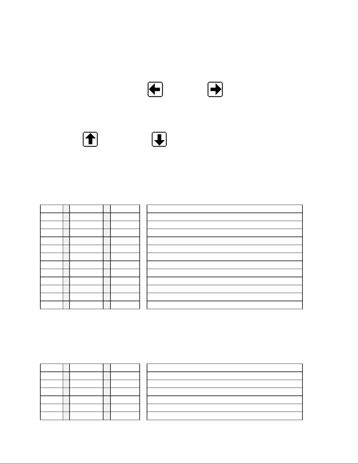
Press right or left arrow keys to display primary or secondary displays.
Use the up (Ç)
The same keys on the hand held remote control would perform the same function.
key or the down (È) key to scroll t hrough th e resultan t displ ays see t able below.
or the right (Æ) can be used to toggle between the
Default Primary-
Temperature.
Tables used to input data.
Primary Display
Shows basic values: Visc. Sg, RT (rate), Mas (mass), Tv(total Volume), Tm( total mass),
Description of resultant displays
ident result units
Default Secondary Displays
Manifold (on/off), Volume (on/off), Raw data: (F) requency1, 2,3, Ros, STr, K factor, A1 temp, Date.
Refer to special settings section for changing settings.
Tables used to input data.
Secondary Display
Description of resultant displays
ident result units
To Change idents and units see section titled DISPLAY IDENTS AND UNITS
3
Page 6

4050 Multi-Input Linear Flow Computer
3. PROGRAMMING THE COX 4050
Entering The Programming Mode
Press the right arrow key until Secondary is displayed. Press the alter key and.’CODE ****’ will be displayed. A
four-digit code can now be entered (serial number). On each press of a key the
sequence from left to right. When all four
shows ‘WRONG CODE’ then try again making sure that you are entering the correct code, as each instrument
has a different code setting. If a mistake is made during setting, then use the CLEAR key and try again.
If you are sure that the code is correct and the instrument still shows WRONG CODE then it is probable that
the batteries need changing in the hand held remote control.
If you press t he A LTE R key b y mi stak e th e dis play wil l reve rt to normal after approx. 20 seco nds. Pres sing the
Å Æ keys will have the same effect. Pressing any other key will reset the timer allowing sufficient time to enter
each digit of code.
Exit program mode by pressing clear.
will change to
‘*’
have been set the code is automatically checked. If the display
‘*’
‘+’
in
The Code Number
The code number for each instrument is taken from the last 4 digits of the serial number. The serial number can
be found on the front page of this manual, on the rear of the instrument, and is also displayed when the
instrument is first powered up, and finally by entering the Front panel Test routine.
For complete security it is recommended that the remote controller should be kept in a safe and secure place.
Unable To Enter A Code?
1) Enabling and disabling the Infrared hand held keypad.
The infra-red keypad will work with any COX unit and therefore it may be necessary to disable this function on
one unit where they are in close proximity. To LOCK OUT the infrared keyboard you must enter the Front Panel
Test Routine and select N for the ENABLE IR control. Once locked out, the infrared keypad is totally inactive on
that particular unit and the lock LED will be lit in the lower square panel. With the REMOTE OFF the displays
may still be viewed by means of the front panel keys. To restore operation of the infra-red keyboard use the
Front Panel Test Routine and select Y to the ENABLE IR menu.
2) Automatic LOCK OUT
In some cases the instrument itself will inhibit the ALTER key as it may be performing a sequence of events
that can not be interrupted, i.e. BATCHING. Please see the special instructions if applicable.
Unable To Use The Keys Or Key Bounce
If you are exper ienc ing key bounce or you are un abl e to us e the keys then there is probably interference with
the infra-red remote control. Problems may occur when trying to operate the unit in
sodium lights etc. If there are problems then please contact your supplier.
direct sunlight;
or using
4
Page 7

4050 Multi-Input Linear Flow Computer
4. PROGRAMMING THE IDENTS AND UNIT LABELS (L/M, PPH, ETC)
1) When in any mode , select th e display to be a ltered using the ÇÈ keys. Note if yo u are a curve menu you
change the units only, this will change all points in that curve.
2) Press the
side of the display.
3) Use the ÇÈ keys to select the required character for that position and the ÅÆ keys to alter the po sition of
the cursor. Using these key, the unit s on the right hand side may be altered.
4) To move the cursor to the left hand side of the display press the
across.
5) Use the ÇÈ keys to select the required character for that position and the ÅÆ keys to alter the position of
the cursor. Using these keys the display designation may be altered.
6) Once the de sired character s have been programmed then pressing t he
display.
7) Use the ÇÈ keys to select another display to be altered and repeat the above sta ges.
IMPORTANT NOTE:
that the display designation is limited to four or fewer charact ers, otherw ise the displ ays will overlap
causing apparent corruption. If this should occur then the number of characters for the display
designation should be reduced, after which the display will return to normal.
In some cases the unit may prevent changes to the display. This is because the instrument needs to
have these displays fixed to run correctly. See any special instructions supplied.
key followed by the
SHIFT
Where a maximum number of digits are to be displayed e.g. on total, it is advised
EXP/UNIT
key and the cursor will begin to flash at the far right hand
ALTER
key and the cursor will move
ENTER
key will store t hem in that
5. FREQUENCY INPUT CARD (EDIT CURVES) K FACTORS VS. F/V
This secti on describes how to program the F low Curve, which t he machine uses to compute the f low rate, by
using The K factor (count s per unit measured) and frequency /viscosity.
1) Display shows ‘EDIT CURVE 1’ or 2 or 3.
2) Press ALTER to display the first point of calibration. Then use the ÇÈ keys to select the required calibration
point to be entered or altered. The left hand display will always show the curve and point number i.e. C
right hand display will show the units, i.e. Hz, Hzv, L/M etc. This label can be changed by pressing the SHIFT
then UNIT key.
3) To enter/alt e r dat a ei t her pres s t he CL E A R k ey or ent er a num er ic v alue . T he mac h ine read s f ro m t he lowes t
to highest K factor and frequency/viscosity, so they should be programmed lowest (first) to highest (last). The
display will show SET on the left indicating that data is being entered. To obtain +/- values press the SHIFT key
followed by the +/- key. To obtain EXP values enter the numeric value followed by the EXP key and the
exponential value. Press the CLEAR key to delete incorrect data entry.
4) Having ent ered the correct va lue, press the ENT ER key and the entered dat a with the channel and point
number will be displaye d
5) Use the ÇÈ key to select the next point of calibration or press the ENTER key to exit this mode and return to the list of
program options.
101
, the
5
Page 8

4050 Multi-Input Linear Flow Computer
CHn Setup
To set up a frequency channel the following will apply, however some items are optional and may not appear in
your specific application.
Display shows CHn SETUP, pressing alte r and using the ÇÈ will show options . Use ALTER to change the
values.
FRQ CUT OFF When below this value of Frequency then FRQ = 0.0
VOL CUT OFF When below this value of volume flow then Vol Flow = 0.0
MASS CUT OFF When below this value of mass flow then Mass Flow = 0.0
TIME BASE Used to calculate flow rate in Kfactors or Total in flow 1, 60 or 3600 based on time
UP DATE TIME 0.02 sec to 9999 secs for update control
FRQ CONSTANT Default 2.0
VOL FACTOR Multiplier Volume flow rate by this factor (for special applications)
MASS FACTOR Multiplier Mass flow rate by this factor (for changing to pounds 8.32778)
ALPHA Alpha factor used for Stro and Ros calculation.
CAL_TEMP Calibration temperature of sensor used for Stro and Ros.
-7
used to adjust the internal crystal frequency.
Sort Curve
Through out the system each curve can be sorted or left as entered. Each curve works from lowest entry to
highest entry
the highest then use the sort curve function.
, if entered this way then the sort routine does not need to be used. If you add a point that is not
Reset Totals
This option allows the user to clear totals, please note that there maybe more than one total, i.e. Volume and
Mass totals, each needs to be cleared! Use the ALTER key when on a RESET VOL 0=Y option to scan for the
next total.
6
Page 9

4050 Multi-Input Linear Flow Computer
BLANK TABLE INTO WHICH DATA MY BE WRITTEN FOR REFERENCE.
K Factor and F/V Data Edit Curve
Meter #1 (Typically Low Flow) Meter #2 (Mid Flow)
K Factors exp F/V K Factors exp F/V
01 01
02
03
04 04
05
06 06
07
08 08
09
10
11 11
12
13 13
14
15 15
16
17
18 18
19
20 20
21
22 22
23
24
25 25
26
27 27
28
29 29
30
31
32 32
02
03
05
07
09
10
12
14
16
17
19
21
23
24
26
28
30
31
7
Page 10

4050 Multi-Input Linear Flow Computer
BLANK TABLE INTO WHICH DATA MY BE WRITTEN FOR REF.
K factor and F/V Data Edit Curve
Meter (High Flow) #3
K Factors exp F/V K Factors exp F/V
01 17
02
03 19
04
05 21
06
07
08 24
09
10 26
11
12 28
13
14
15 31
16
18
20
22
23
25
27
29
30
32
6. ANALOGUE INPUT CARD EDIT CURVES
Set Viscosity/ Set S.G.
This section describes how to program Specific Gravity and Viscosity for an individual chemical and its
characteristics.
1) Display shows ‘Temperature’/ ‘Viscosity’ or ‘S.G. ‘set’ or another option
2) Press ALTER to display the first point of calibration. Then use the ÇÈ keys to select the required calibration
point to be entered or altered. The left hand display will always show the curve and point number i.e. C
right hand display will show the units, i.e.
then UNIT key.
3) To enter/al ter data ei ther press the CLEA R key or ent er a numeric v alue. The dis play will show SE T on the
left indicating that data is being entered. To obtain +/- values press the S HIFT key followed by the +/- key. To
obtain EXP values enter the numeric value followed by the EXP key and the exponential value. Press the
CLEAR key to delete incorrect data entry.
4) Having ent ered the correct va lue, press the ENT ER key and the entered dat a with the channel and point
number will be displaye d
5) Use the ÇÈ key to select the next point of calibration or press the ENTER key to exit this mode and return to
the list of program options.
O
C, CTS, S.G. etc. This label can be changed by pressing the SHIFT
101
, the
Sort Curve And Vis Temp Etc.
Through out the system each curve can be sorted or left as entered. Each curve works from lowest entry to
highest entry, if entered this way then the sort routine does not need to be used. If you add a point that is not
the highest then use the sort curve function.
8
Page 11

4050 Multi-Input Linear Flow Computer
BLANK TABLE INTO WHICH DATA MY BE WRITTEN FOR REFERENCE.
Set Viscosity Set Specific Gravity
Temperature
01
02
03
04
05
06
07
08
09
10
11
12
13
14
15
16
17
18
19
20
21
22
23
24
25
26
27
28
29
30
31
32
Viscosity Temperature S.G.
7. FRONT PANEL TEST MODE
By pressing the ÅÆ at the same time the front panel set up and test mode are entered.
The display will show the following options by pressing the ÇÈ.
ENABLE IR Y User alter to enable Y and disable N the IR keyboard
KEY CLICK N User alter to select Y and disable N the audible key click
TEST REMOTE Ç Test the IR keyboard
MAN 1234 Serial number of unit
ALTER TO EXIT
Press ALTER to exit this mode
9
Page 12

8. RS232 / RS485
4050 Multi-Input Linear Flow Computer
Command Structure.
Viewing data from th e Mul tiflow;
All data is sent and received as ASCII HEX pairs, the maths used in PIC Hex format, 2 exam ple routines are
included to convert this data into PC or ASCII strings. The PIC Hex format is always 4 bytes and represents a
32-bit floating-point number system. To read data use the following format.
Description ID View Hub/Slot Reg/Mem Slot Address No.Bytes CR
String a V H R 00A0 04 CR
Hex 61 56 48 52 00A0 04 0D
ASCII Hex 36 31 35 36 34 38 35 32 30 30 41 30 30 34 0D
Notes: Reg/Memory all ows the user to view live data within the Processors own working registers or the Flash
memory address space that is used to store constant and curve data. The Hub is the main process or (the card
connected to the serial link), whilst the SLOTs need to be addressed as follows.
Description ID View Hub/Slot Reg/Mem Slot Address No.Bytes CR
String a V S M 04 0600 04 CR
Hex 61 56 49 4D 04 0600 04 0D
ASCII Hex 36 31 35 36 34 39 34 44 30
30 36 30 30 30 34 0D
34
SLOT ID Hex Ascii Hex Position
4 04 30 34 1A
5 05 30 35 1B
6 06 30 36 1C
7 08 30 38 2A
8 09 30 39 2B
9 0A 30 41 2C
10 0C 30 43 3A
11 0D 30 44 3B
12 0E 30 45 3C
13 10 31 30 4A
14 11 31 31 4B
15 12 31 32 4C
16 14 31 34 5A
17 15 31 35 5B
18 16 31 36 5C
General Address.
To obtain the list address for your instrument please send email to ed-s@s-k.com
also included are the conversion routines of the PicHex to st andard PC/Ascii data.
Char output FAST M EDIUM or SLOW
to request a complete list,
Computer interface information
Port Settings.
The display shows menu ‘SETUP COMMS’, press ALTER to select the possible sub menus
BAUD 19200 Baud rate change using ALTER to 9600, 1200 or 19200
READ ONLY At present the system is set to read only
ID a Use ALTER to scan Ids a to z lower case only
RS485 FAST Delay for bus transceiver FAST MEDIUM or SLOW
COMMS FAST Delay between Char output FAST MEDIUM or SLOW
10
Page 13

4050 Multi-Input Linear Flow Computer
PIN SETTINGS.
RS232 RS485
9 way D, Pin 2 RX B
Pin 3 TX A
Pin5 0v 0v
Label27.Caption = b
Sub cal_dec(dec, result, dp_pos, result_str)
dec = 0
eb = Left$(result, 2)
If eb = "00" Then GoTo the_res_is_zero
sethex = Right$(result, 6)
e = Val("&h" + eb) - 127
bin_data = ""
For p = 1 To 6
Select Case UCase(Mid$(sethex, p, 1))
Case "0" nibble = "0000"
Case "1" nibble = "0001"
Case "2" nibble = "0010"
Case "3" nibble = "0011"
Case "4" nibble = "0100"
Case "5" nibble = "0101"
Case "6" nibble = "0110"
Case "7" nibble = "0111"
Case "8" nibble = "1000"
Case "9" nibble = "1001"
Case "A" nibble = "1010"
Case "B" nibble = "1011"
Case "C" nibble = "1100"
Case "D" nibble = "1101"
Case "E" nibble = "1110"
Case "F" nibble = "1111"
End Select
bin_data = bin_data + nibble
Next p
If Left$(bin_data, 1) = "1" Then
sign = "-"
Else
sign = ""
End If
dec = 1
For p = 2 To Len(bin_data)
Bit = Mid$(bin_data, p, 1)
If Bit = "1" Then dec = dec + 2 ^ -(p - 1)
Next
dec = (2 ^ e) * dec
wiv_sign = sign + Str(dec)
dec = Val(wiv_sign)
the_res_is_zero:
Select Case Val(dp_pos)
Case 1
result_str = Format(dec, "0.0")
Case 2
result_str = Format(dec, "0.00")
Case 3
result_str = Format(dec, "0.000")
Case 4
result_str = Format(dec, "0.0000")
Case 5
result_str = Format(dec, "0.00000")
Case 6
result_str = Format(dec, "0.000000")
Case 7
result_str = Format(dec, "0.0000000")
Case 8
result_str = Format(dec, "0.00000000")
Case 9
result_str = Format(dec, "0.000000000")
Case Else
result_str = Format(dec, "0")
End Select
Code Examples:
Cal_dec(returned decimal value, asciihex string from input buffer 8 bytes, number of decimal places, returned ascii
string)
cal_dec(a, Left$(rx_buff, 8), 3, b)
End Sub
11
Page 14

4050 Multi-Input Linear Flow Computer
9. SPECIAL OPTIONS
(Under Secondary)
Setting RTC
Setting the real time clock. When either the time or the date is viewed pressing ALTER will enable the user to
set the time/date.
Manifold ON/OFF
When this display is showing, pressing ALTER on the IR keyboard will toggle this selection, ON or OFF. When
off a manual option is enabled. This option allows the user to set the machine up for multiple meters and a relay
state change at a particular set points.
Manifold Autoranging Trip Points (Section 12)
Used for switching valves etc. These values are set for at what point relays open or close (usually used to
control valves).
Under the menu system the display will show SETUP AUTO pressing alter will display the following. Access by
using the ↑↓.
1
2
3
2
These values should not be set above or below the next meters calibration figures, leave some space for the
meter to switch over. An example is if meter 1 is set & calibrated for 20(1gpm) to 1100 hz(100gpm) and meter 2
at 100(85gpm) to 1000hz(500gpm) set trip point 1 to 2 at about 1000hz(saying 1000Hz= 92gpm) and set 2 to
1trip point at about 110 hz (sayi ng 110Hz = 90gpm) .This allows room for som e varian ce and avoids 4050 being
in a switching loop.
The user should take care to enter a reasonable hysterisis. Refer to section 12 for the relay truth table.
Channel “ # ”
This display shows the current channel number running, however if the MANIFOLD OFF option is running then
pressing the ALTER key will change the channel number, (relay and analogue output)
VOL ON / MASS ON
Pressing ALTER (IR Keyboard) will select the VOLume or The MASS to be running. The effect is:
↑
2 0.0 Hz This shows the trip point in Hertz from meter 1 (Chan 1 low flow) to 2
↑
3 0.0 Hz This shows the trip point in Hertz from meter 2 (Chan 2. medium flow) to 3
↓
2 0.0 Hz This shows the trip point in Hertz from meter 3 (Chan 3. high flow) to 2
↓
1 0.0 Hz This shows the trip point in Hertz from meter 2 (Chan 2. medium flow) to 1
1. Each time t he AUTO MANIFOLD changes the display will change to the new channel and display
either the VOLume or the MASS flow rate.
2. If fitted the analogue output will represent Volume or Mass flow rate.
12
Page 15

4050 Multi-Input Linear Flow Computer
10. PROGRAMMING HELPER
Primary
(Basic settings)
Computed Data
Viscosity Frequency 1, 2 &3 Set-up Auto (Hz Trip points)
Specific Gravity Roshkoe Cards Fitted
Volume Rate 1, 2 & 3 Strouhal Set-up Comms
Mass 1, 2 & 3 K factor 1, 2 & 3 Edit Curve
Total Volume A1 Temperature =
Temperature Date Clear Totals
Manifold(on/off) Sort Curve
Volume(on/ off) Set Viscosity
Raw Data Settings
ma
Secondary
Program Mode
Enter by pressing ALT &
Serial #
(what cards are installed)
(Port settings)
(K Factor Programming)
Channel set-up 1, 2, 3
(programming fluid data)
Set specific Gravity
(programming fluid data)
Set Temperature
(setting C or F by ranging ma
output)
Set-up Inputs
(system changes not
recommended)
Sort Vis/Sg/Temp
13
Page 16
4050 Multi-Input Linear Flow Computer
11. WIRING DIAGRAM TERMINALS
COMPENSATION
JUMPER FOR TEMP.
TB RELAYS
1 NO RELAY 1 +SIG 1 V OR I SPECIAL IP 1
2 COMMON 0v SPECIAL IP 2
3 NO RELAY 2 +SIG 2 V OR I EX. VOLTAGE Meter input Vdc 3
4 COMMON 0v + SIGNAL 1 4
5 NO RELAY 3 +RTD PROBE - SIGNAL 1 or 0v 5
6 COMMON 0v 0v 6
7 +RTD PROBE EX. VOLTAGE Meter input Vdc 7
8 0v + SIGNAL 2 8
9 -RTD - SIGNAL 2 or 0v 9
10 0v 0v 10
11 -RTD EX. VOLTAGE Meter input Vdc 11
12 0v + SIGNAL 3 12
13 +12v Output - SIGNAL 3 or 0v 13
14 0v 0v 14
3 2 1
SLOT
ANALOGUE IN
SLOT
FREQUENCY
SLOT
3 2 1
1 2 3 4 5 6 7 8 9 10 11 12 13 14
Fuse on/off switch
Mcon1
123456
Mcon1 1 +24vDC input from 100mA to 200mA (depends on cards fitted)
2 0v
3 0v
4 +24vDC output repeated from input 1 or when on Main supply
5 Optional relay C
6 Optional relay NO
Mains input 80 to 265 ac auto. Fuse 1.0 amp.
HubCon
1 Fused 5vDC
2 Open Collector Output
3 SW1 input
4 SW2 input
5 SW3 input
6 0v
Slot # 3 2 1
1 2 3 4 5 6
Hub con
14
Page 17
4050 Multi-Input Linear Flow Computer
,12,
,
,
,7,9,
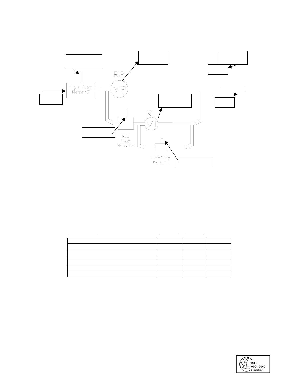
12. MANIFOLD SYSTEM INSTALLATION EXAMPLE
Flow
S1/P 11
13
S 1/ P7,8,9
(S) Slot –(V) Valve (R ) Relay (P) Pins
Relay2
S3/ P 3
4
Relay 1
S3/ Pins 1
RTD
2
S 1/P 3,4,5
S 2
P 5
Flow
11
Truth Table for Relays
Relays are dry outputs with open (o) or closed (c) states, which can be used to switch valves etc.
CONDITION
No power to unit O O O
Power On No Flow C C O
Low Flow C C O
1 to 2 trip point (Flow at 2) O C O
2 to 3 trip point (Flow at 3) O O O
3 to 2 trip point O C O
2 to 1 trip point C C O
RELAY 1 RELAY 2 RELAY 3
090804
15
 Loading...