

Page 1
Flow Sensor
Series 4000
SEN-UM-01714-EN-01 (April 2018)
User Manual
Page 2

Flow Sensor, Series 4000
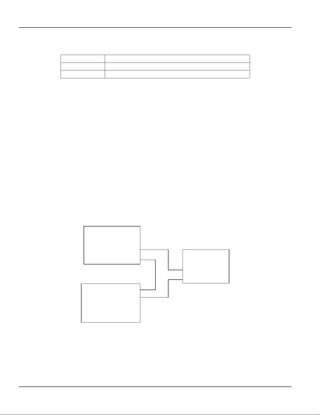
CONTENTS
Introduction. . . . . . . . . . . . . . . . . . . . . . . . . . . . . . . . . . . . . . . . . . . . . . . . . . . . . . . . . . . . . . . . . . . . . . . . . .4
Mechanical Installation. . . . . . . . . . . . . . . . . . . . . . . . . . . . . . . . . . . . . . . . . . . . . . . . . . . . . . . . . . . . . . . . . . .4
Vibration . . . . . . . . . . . . . . . . . . . . . . . . . . . . . . . . . . . . . . . . . . . . . . . . . . . . . . . . . . . . . . . . . . . . . . . . . 4
Accuracy . . . . . . . . . . . . . . . . . . . . . . . . . . . . . . . . . . . . . . . . . . . . . . . . . . . . . . . . . . . . . . . . . . . . . . . . . 4
Installation for PVC Sensors . . . . . . . . . . . . . . . . . . . . . . . . . . . . . . . . . . . . . . . . . . . . . . . . . . . . . . . . . . . . . 5
Installation of PVDF Sensors. . . . . . . . . . . . . . . . . . . . . . . . . . . . . . . . . . . . . . . . . . . . . . . . . . . . . . . . . . . . .5
Electrical Installation . . . . . . . . . . . . . . . . . . . . . . . . . . . . . . . . . . . . . . . . . . . . . . . . . . . . . . . . . . . . . . . . . . . . 6
Electrical Wiring for a Digital Unit . . . . . . . . . . . . . . . . . . . . . . . . . . . . . . . . . . . . . . . . . . . . . . . . . . . . . . . . . 6
Electrical Wiring for an Analog Unit . . . . . . . . . . . . . . . . . . . . . . . . . . . . . . . . . . . . . . . . . . . . . . . . . . . . . . . . 6
Maintenance . . . . . . . . . . . . . . . . . . . . . . . . . . . . . . . . . . . . . . . . . . . . . . . . . . . . . . . . . . . . . . . . . . . . . . . . . 7
Impeller Assembly and Shaft Replacement . . . . . . . . . . . . . . . . . . . . . . . . . . . . . . . . . . . . . . . . . . . . . . . . . . . 7
Electronic Assembly Replacement . . . . . . . . . . . . . . . . . . . . . . . . . . . . . . . . . . . . . . . . . . . . . . . . . . . . . . . . .8
Detecting Coil Replacement. . . . . . . . . . . . . . . . . . . . . . . . . . . . . . . . . . . . . . . . . . . . . . . . . . . . . . . . . . . . .8
Calibration. . . . . . . . . . . . . . . . . . . . . . . . . . . . . . . . . . . . . . . . . . . . . . . . . . . . . . . . . . . . . . . . . . . . . . . . . . .9
Theory of Operation. . . . . . . . . . . . . . . . . . . . . . . . . . . . . . . . . . . . . . . . . . . . . . . . . . . . . . . . . . . . . . . . . .9
Sensor Calibration . . . . . . . . . . . . . . . . . . . . . . . . . . . . . . . . . . . . . . . . . . . . . . . . . . . . . . . . . . . . . . . . . . . 9
Calibration Pipe Material . . . . . . . . . . . . . . . . . . . . . . . . . . . . . . . . . . . . . . . . . . . . . . . . . . . . . . . . . . . . . .10
Specications . . . . . . . . . . . . . . . . . . . . . . . . . . . . . . . . . . . . . . . . . . . . . . . . . . . . . . . . . . . . . . . . . . . . . . . .11
Wetted Materials . . . . . . . . . . . . . . . . . . . . . . . . . . . . . . . . . . . . . . . . . . . . . . . . . . . . . . . . . . . . . . . . . . . 11
Digital Meter Specications . . . . . . . . . . . . . . . . . . . . . . . . . . . . . . . . . . . . . . . . . . . . . . . . . . . . . . . . . . . . 11
Analog Meter Specications. . . . . . . . . . . . . . . . . . . . . . . . . . . . . . . . . . . . . . . . . . . . . . . . . . . . . . . . . . . .12
Technical Specications . . . . . . . . . . . . . . . . . . . . . . . . . . . . . . . . . . . . . . . . . . . . . . . . . . . . . . . . . . . . . . 13
Pressure, Temperature Diagram . . . . . . . . . . . . . . . . . . . . . . . . . . . . . . . . . . . . . . . . . . . . . . . . . . . . . . . . . 14
Dimensions . . . . . . . . . . . . . . . . . . . . . . . . . . . . . . . . . . . . . . . . . . . . . . . . . . . . . . . . . . . . . . . . . . . . . . . . . 15
Troubleshooting . . . . . . . . . . . . . . . . . . . . . . . . . . . . . . . . . . . . . . . . . . . . . . . . . . . . . . . . . . . . . . . . . . . . . . 16
General . . . . . . . . . . . . . . . . . . . . . . . . . . . . . . . . . . . . . . . . . . . . . . . . . . . . . . . . . . . . . . . . . . . . . . . . . 16
Check Using a Digital Circuit . . . . . . . . . . . . . . . . . . . . . . . . . . . . . . . . . . . . . . . . . . . . . . . . . . . . . . . . . . . 16
Checking the Sensor . . . . . . . . . . . . . . . . . . . . . . . . . . . . . . . . . . . . . . . . . . . . . . . . . . . . . . . . . . . . . .16
Checking the Electronic Module . . . . . . . . . . . . . . . . . . . . . . . . . . . . . . . . . . . . . . . . . . . . . . . . . . . . . .16
Checking the Impeller . . . . . . . . . . . . . . . . . . . . . . . . . . . . . . . . . . . . . . . . . . . . . . . . . . . . . . . . . . . . .17
Check Using an Analog Circuit . . . . . . . . . . . . . . . . . . . . . . . . . . . . . . . . . . . . . . . . . . . . . . . . . . . . . . . . . . 17
Programming. . . . . . . . . . . . . . . . . . . . . . . . . . . . . . . . . . . . . . . . . . . . . . . . . . . . . . . . . . . . . . . . . . . . . . . .18
Connecting Via DIC COM Port. . . . . . . . . . . . . . . . . . . . . . . . . . . . . . . . . . . . . . . . . . . . . . . . . . . . . . . . . . .18
Page 2 April 2018SEN-UM-01714-EN-01
Page 3

Flow Sensor Conguration Section. . . . . . . . . . . . . . . . . . . . . . . . . . . . . . . . . . . . . . . . . . . . . . . . . . . . .21
Analog Loop Settings . . . . . . . . . . . . . . . . . . . . . . . . . . . . . . . . . . . . . . . . . . . . . . . . . . . . . . . . . . . . .21
Flow Rate Filter . . . . . . . . . . . . . . . . . . . . . . . . . . . . . . . . . . . . . . . . . . . . . . . . . . . . . . . . . . . . . . . . .21
Replacement Part Numbers . . . . . . . . . . . . . . . . . . . . . . . . . . . . . . . . . . . . . . . . . . . . . . . . . . . . . . . . . . . . . . .22
Part Number Matrix . . . . . . . . . . . . . . . . . . . . . . . . . . . . . . . . . . . . . . . . . . . . . . . . . . . . . . . . . . . . . . . . . 23
Electronics Repair Kit Part Number Matrix . . . . . . . . . . . . . . . . . . . . . . . . . . . . . . . . . . . . . . . . . . . . . . . . . . . 24
Page 3 April 2018 SEN-UM-01714-EN-01
Page 4

Introduction
INTRODUCTION
The Series 4000 Flow Sensor has an in line, flow-through design using a tangential six bladed impeller. The Sensor is
available in 1/2 in. (12.70 mm), 3/4 in. (19.05 mm) and 1 in. (25.40 mm) pipe sizes, and a wide range of pressure and
temperature specifications.
The sensors have a molded housing, rotating impeller and externally mounted electronics housing using a proprietary,
nonmagnetic sensing technology. The closed, six-bladed impeller design provides higher and more constant torque than
four-bladed designs, and is less prone to fouling by water borne debris. The shape of the impeller and the absence of
magnetic drag provides improved operation and repeatability even at low flow rates. The housing design allows the impeller,
bearings, shaft or O-rings to be cleaned or replaced without removing the sensor from the piping system.
Two signal output options are available. One option is a square wave frequency proportional to flow rate. Power for the circuit
is provided by an external source through a three-wire shielded cable. An internal preamplifier allows the signal to travel a
maximum of 2000 ft (609 m) without amplification, and 20 ft (6 m) of three-conductor cable is included. The second output
option is a 4…20 mA current analog signal. Power is provided by the two-wire loop so the distance from the receiver is a
function of power supply voltage and wire resistance. A maximum 30 in. (762 mm) connector cable is included.
Sensors of similar type are interchangeable, so there is no need for recalibration after servicing or replacement.
Theory of Operation
The Sensor operates by converting kinetic energy (in the flow stream) into rotation (of an impeller). Almost all flow
sensors work on the principle of converting flow energy to output signals. The only arguable exceptions are ultrasonic and
electromagnetic sensors. The interaction of the flow stream and the impeller depend, to a currently unquantified extent, on
fluid properties (density, viscosity, and pressure) and on physical properties of the impeller. The Badger Meter impeller design
features the following:
• A low mass polar moment of inertia
• No magnetic drag
• Very low eddy current drag
• Low bearing friction
The impeller housing forms the periphery of a rotating fluid stream, the only source of drag tending to retard the impeller.
The efficiency of this design is the key to the repeatability of sensor output at very low flow rates, and is the reason that the
pressure drop across the installed sensor is so low.
MECHANICAL INSTALLATION
Vibration
There is a direct relationship between sensor housing vibration levels and impeller wear. Sensors mounted in a low vibration
region (close to pipe supports) consistently give longer bearing life than those mounted in a high vibration region. The
difference in bearing life persists, independent of impeller and shaft materials, or methods of construction. The wear is most
obvious at high flow rates, when high levels of pipe vibration are most pronounced.
When mounting a Sensor, minimize housing vibration using either of the following methods:
• Mount the sensor as close as possible to a stable, low vibration, anchored inlet or outlet pipe. Provide 10 diameters
upstream and 5 diameters downstream of straight pipe.
• Provide pipe supports, on both sides of the sensor, that are firmly anchored to a stable platform. This is particularly
important if the sensor is mounted in the approximate center of a pipe section two feet long between supports.
You must minimize sensor vibration, or sensor accuracy will be affected and impeller life reduced.
Page 4 April 2018SEN-UM-01714-EN-01
Page 5

Mechanical Installation
Accuracy
The accuracy of flow measurement depends on proper location of the sensor in the piping system. Irregular flow velocity
profiles caused by valves, fittings and pipe bends can produce inaccurate overall flow rate indications even though local
velocity measurement might be accurate. A sensor located in the pipe where it can be affected by air bubbles, floating debris,
or sediment might not achieve full accuracy, and could be damaged. Follow these directions for maximum system accuracy:
• Install the sensor in a pipe with 10 pipe diameters of straight pipe upstream and 5 pipe diameters of straight pipe
downstream of the sensor for no flow disturbance. Allow no pipe bends, valves, other fittings, pipe enlargements and
reductions in this length of pipe.
• For horizontal flow applications, install the sensor with the curved portion of the housing down. Sensors installed with
the curved portion in the up position trap air, causing inaccurate flow measurement, especially at low flows. Sensors
installed with the curved portion pointing sideways not only trap air, but increase impeller friction, which might also affect
measurements at low flow rates. Install the sensor to facilitate servicing.
• The preferred vertical location is with liquids flowing up. If vertical flow downward is the only option, the pipe must be
completely filled with fluid. Any circumferential orientation is correct, but the sensor location should facilitate servicing. A
vertical location might result in reduction of accuracy.
• Mount sensors with a minimum of 3 in. (75 mm) clearance in all directions around the gray electronics assembly to prevent
electro-mechanical interference. This space requirement applies to multiple sensor sensors installed in close proximity as
well as to other EMI generators, such as electric motors or controls for motors, heaters or lighting.
Installation for PVC Sensors
Any compatible size and type of fitting or adapter can be connected to the pipe nipples by thermal or solvent welding. Make
sure the fittings and method you choose to install the PVC unit comply with American Society for Testing and Materials
(ASTM) standards. Install the sensor so the arrow in the stainless steel cover is pointing the same direction as the flow of the
fluid. Do not connect directly to reducing or enlarging fittings. Install an additional 10 diameter upstream and five diameter
downstream allowance if this is unavoidable.
Installation of PVDF Sensors
PVDF sensors are supplied with combination end connections. A Heat Weld Female Slip connection can accept most metric
sized PVDF pipes. The external thread is used with George Fisher type Unions. Badger Meter® offers PVDF, 316SS FNPT, and
CPVC Slip Socket Union Ends.
In PVDF sensors with the enhanced flow feature, the flow enhancement jet must be inserted before installing the sensor into
the system. With the stainless steel cover facing you, insert the jet into the left socket (upstream end) and then perform the
method chosen for installation. Install the sensor with the arrow on the stainless steel cover pointing in the same direction
as the flow of the liquid. Follow the same ten and five diameter upstream and downstream allowance and orientation
recommendations, as described in "Installation for PVC Sensors".
Page 5 April 2018 SEN-UM-01714-EN-01
Page 6
Electrical Installation
ELECTRICAL INSTALLATION
Sensor part Cable supplied
Digital Transmitter 20 ft (6 m) of 20 AWG three-conductor cable with drain wire and shield
Analog Unit 30 in. (762 mm) of AWG two-conductor cable with drain wire and shield
Make electrical wiring connections according to accepted trade practices.
You can attach an electrical junction box directly to the sensor electronic module, or mount it in the vicinity of the sensor.
Locate it conveniently to facilitate replacement of the electronic module assembly. Do not subject the wiring connections to
water or conductive liquids, as these might impair operations or damage the sensor circuitry.
When connecting to the electronic device, observe the wire colors and polarity to allow proper performance and to prevent
damage to the sensor or electronic device.
Electrical Wiring for a Digital Unit
Below are the general wiring instructions for the digital output unit. If you are connecting to a Badger Meter flow monitor,
consult the user manual.
1. Connect the red sensor wire to the positive (+) wire or terminal.
2. Connect the black sensor wire to the negative (–) wire or terminal.
3. Connect the white sensor wire to the signal (S) wire or terminal.
4. Connect the bare sensor wire to sensor shield.
Electrical Wiring for an Analog Unit
Turn off the 4…20 mA power and finish all wiring before turning on the loop power.
1. Wire the red wire (+ analog loop) of the ow sensor to the positive (+) output of a DC power supply.
2. Wire the black wire (– analog loop) of the ow sensor to the positive (+) input of your analog device.
3. Wire the negative (–) input of your analog device to the negative (–) of the DC power supply.
Power Supply
10...35V DC
(– output) DC
(+ output) DC
(+ analog loop) Red
(- analog loop) Black
4xxx10-xxxx
Flow Sensor
Figure 1: Wiring for analog 4000
Analog Input
Device
(–) Input
(+) Input
OTE:N Some legacy units may have additional orange and brown wires. Do not connect these wires. Connecting to these
wires will damage the unit and void the warranty. They are for factory calibration only.
Calibration
If you are replacing an existing sensor and have already calibrated your flow monitor, no calibration changes are necessary.
For installation of a new flow monitor, please refer to the calibration instructions in the flow monitor manual.
Page 6 April 2018SEN-UM-01714-EN-01
Page 7
Maintenance
MAINTENANCE
Impeller Assembly and Shaft Replacement
The following tools are required for the replacement of the impeller and shaft:
• 5/32 in. Allen wrench
• Flat blade screwdriver
• Torque driver in in-lb with 5/32 in. male hex adapter
OTE:N Units are factory calibrated at 12 in-lb.
1. Depressurize the pipe on which the sensor is being serviced.
DO NOT REMOVE SOCKET HEAD CAP SCREWS WHILE SYSTEM IS UNDER PRESSURE.
2. Using the Allen wrench, loosen and remove the four #10 socket head cap screws along with the stainless steel cover. It is
not necessary to remove the electronics to service the impeller and shaft.
3. Use the at-blade screwdriver to pry the impeller cover/shaft assembly from the sensor housing by using the provided
slots alternately.
4. Inspect the impeller and impeller cover/shaft assembly for signs of wear.
5. Replace the O-rings before reassembly. Do not use lubricants on the O-rings.
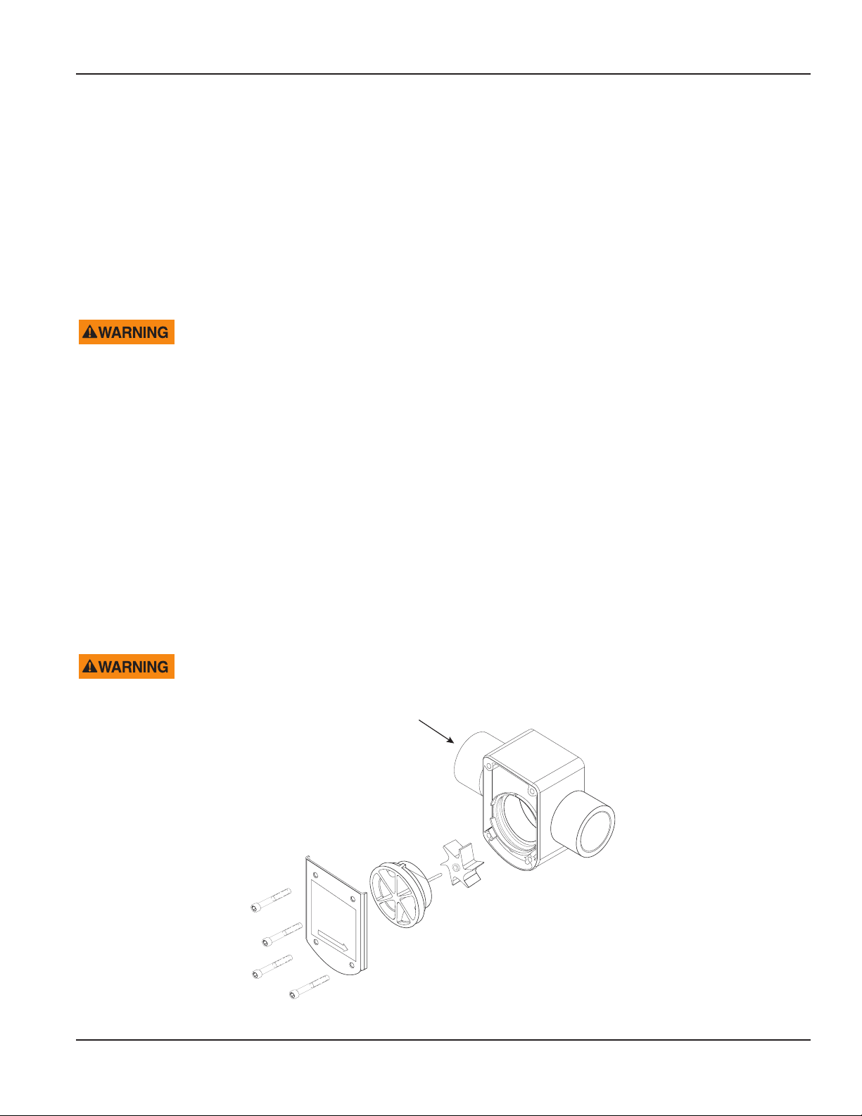
6. Insert the impeller into the cavity of the sensor housing, making sure the six blades are pointing into the ow direction.
The unit does not operate if the impeller is positioned incorrectly. For example, if ow direction is to the right, position the
impeller with blades pointing to the left. See Figure 2.
7. Orient the keyway of the impeller cover/shaft assembly to the small slot between the two large slots and align the shaft to
the shaft hold of the impeller.
8. Hand press the impeller cover/shaft assembly into the sensor housing cavity.
9. Fasten the stainless steel cover to the sensor housing using the #10 socket head cap screws.
10. Torque the #10 hardware to 12 in-lb.
11. Pressurize the system.
ALL FOUR SCREWS MUST BE IN PLACE AND TORQUED CORRECTLY BEFORE PRESSURIZING SYSTEM!
Flow
Direction
PVC Version
Impeller
Impeller Cover/Shaft Assembly
Stainless Steel
Cover
#10 Hardware
Figure 2: Assembly and shaft replacement
Page 7 April 2018 SEN-UM-01714-EN-01
Page 8
Maintenance
Electronic Assembly Replacement
A #1 Phillips screwdriver is required for servicing electronics. It is not necessary to depressurize or drain the system to service
the electronics.
1. Disconnect the sensor wiring from the display or transmitter.
2. Using a Phillips screwdriver, remove the two #4 Phillips head screws and accompanying hardware.
LETTING THE ELECTRONIC ASSEMBLY DROP FROM THE SENSOR COULD DAMAGE THE DETECTING COIL.
3. Unplug the coil from the electronics
OTE:N On analog units, the coil is permanently attached to electronics.
4. Plug the coil into the replacement electronics.
5. Reattach the electronics to the sensor with the two #4 Phillips screws. See "Replacement Part Numbers" on page 20 for
replacement part numbers.
MPORTANTI
Make sure the wires from the coil are tucked in before tightening the screws.
Detecting Coil Replacement
A #1 Phillips screwdriver is required for replacing the detecting coil. Depressurizing or draining the system is not necessary for
detecting coil replacement.
1. Remove the electronic assembly like in step 1 in "Electronic Assembly Replacement".
2. Unplug the coil from the electronics.
3. Using a Phillips screwdriver, remove the two #6 Phillips head screws, and the coil retaining plate.
4. Secure new coil to sensor housing with the #6 hardware.
5. Plug the replacement coil into the electronic assembly.
6. Fasten the electronics to the sensor with the #4 hardware. The coil wire orientation is not critical to operation. See
"Replacement Part Numbers" on page 20 for replacement part numbers.
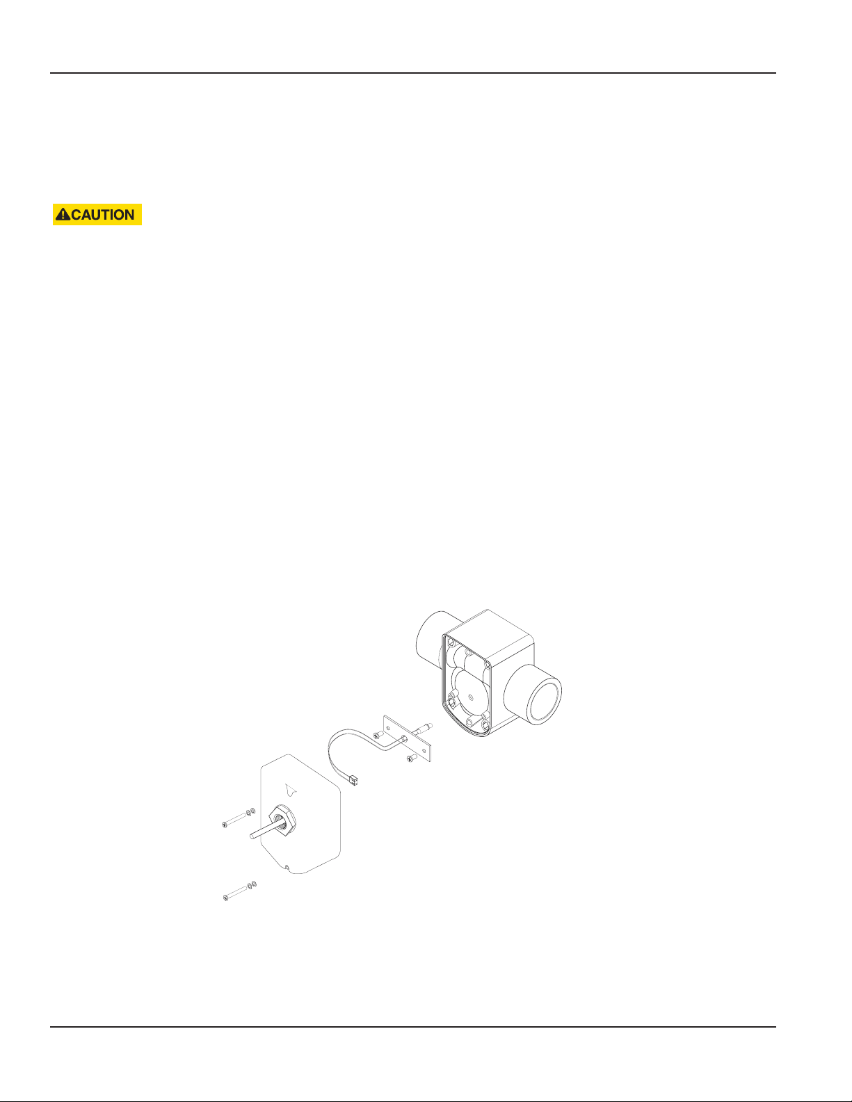
Coil
Coil Retaining Plate
#6 Hardware
Electronic
Assembly
#4 Hardware
Figure 3: Coil and electronic assembly replacement
Page 8 April 2018SEN-UM-01714-EN-01
Impeller Body
Page 9

SPECIFICATIONS
Wetted Materials
• Sensor Housing and Enhancing Jet (If Applicable)
• PVC - Virgin polyvinyl chloride, type 1, grade 1
• PVDF - Virgin polyvinylidene fluoride
Digital Meter Specications
Specications
Sensor
Model #
400200 PVC 1/2 #80 0.08 (2.13) 0.55 (13.97) 0.413 0.3496 0.75 15.00 1.46 35.97
401200 PVC 3/4 #80 1.05 (26.67) 0.82 (20.83) 0.5735 0.2638 1.75 35.00 2.78 60.76
402000 PVC 1 #80 1.32 (33.40) 0.96 (24.38) 0.6134 0.1826 2.25 45.00 3.48 73.17
410200 PVC
411200 PVC
400300
400400
400500
401300
401400
401500
402300
402400
402500
410300
410400
410500
411300
411400
411500
Housing
Material
PVDF 1/2 0.79 (20.00) 0.64 (16.26) 0.5987 0.0008 1.00 20.00 1.66 33.40
PVDF 3/4 0.98 (24.99) 0.84 (21.34) 0.613 0.02664 1.75 35.00 2.82 57.06
PVDF 1 1.26 (32.00) 1.07 (27.18) 0.6266 0.0314 3.00 50.00 4.75 79.76
PVDF
PVDF
Nominal Pipe
Size (in.)
1/2 #80 Enhanced
Low Flow
3/4 #80 Enhanced
Low Flow
1/2 Enhanced
Low Flow
3/4 Enhanced
Low Flow
Pipe OD
in. (mm)
0.08 (2.13) 0.55 (13.97) 0.1421 0.8474 0.18 6.00 0.48 41.37
1.05 (26.67) 0.82 (20.83) 0.3287 0.2159 0.40 13.00 1.00 39.33
0.79 (20.00) 0.64 (16.26) 0.1445 0.4841 0.25 8.00 1.24 54.87
0.984 (25) 0.84 (21.34) 0.3195 0.4679 0.40 14.00 0.78 44.28
Pipe ID
in. (mm)
Slope
K
Offset
Min Flow
Rate
(GPM)
Max Flow
Rate
(GPM)
Min
Pulse
Rate
(Hz)
The calibration constants in columns Slope K and Offset relate frequency (Hz) to flow rate (GPM) in the equations:
Max
Pulse
Rate
(Hz)
FREQ =
GPM = K (FREQ + Offset)
GPM
K
–Offset
Page 9 April 2018 SEN-UM-01714-EN-01
Page 10

Specications
Analog Meter Specications
Analog versions of the sensor are precalibrated at the factory using the flow ranges below.
Sensor
Model #
400210 PVC 1/2 #80 0.08 (2.13) 0.55 (13.97) 0 20
401210 PVC 3/4 #80 1.05 (26.67) 0.82 (20.83) 0 30
402010 PVC 1 #80 1.32 (33.40) 0.82 (20.83) 0 30
410210 PVC 1/2 #80 0.08 (2.13) 0.55 (13.97) 0 8
411210 PVC 3/4 #80 1.05 (26.67) 0.82 (20.83) 0 12
400310
400410
400510
401310
401410
401510
402310
402410
402510
410310
410410
410510
411310
411410
411510
Housing
Material
PVDF 1/2 in. 0.79 (20.00) 0.64 (16.26) 0 20
PVDF 3/4 in. 0.98 (24.99) 0.84 (21.34) 0 30
PVDF 1 in. 1.26 (32.00) 1.07 (27.18) 0 40
PVDF 1/2 in. 0.79 (20.00) 0.64 (16.26) 0 8
PVDF 3/4 in. 0.98 (24.99) 0.84 (21.34) 0 12
Nominal Pipe
Size (in.)
Pipe OD
in. (mm)
Pipe ID
in. (mm)
Min Flow
Rate 4 mA
Max Flow
Rate 20 mA
Page 10 April 2018SEN-UM-01714-EN-01
Page 11

Technical Specications
Viton® Neoprene®
O-Rings
Impeller Shafts
Process Connections
Impeller and Bearing Tefzel®
Nominal Pipe Size 1/2 in. (12.70 mm), 3/4 in. (19.05 mm), 1 in. (25.40 mm)
End Connections
Max Temp Rating
Max Pressure Rating
Pressure, Temperature
Ratings
Cable
Digital Output Unit
Analog Output Unit
Operating Flow Range
Recommended Design
Flow Range
Accuracy
Repeatability ±0.5% of full scale over recommended design flow range
Linearity
EPDM Chemraz®
Kalrez® Teflon® Encapsulated Viton
Silicon, food grade —
Zirconia Ceramic Monel,® Grade K500
Hastelloy,® C-276 316 stainless steel
Tungsten Carbide, GE carboloy 883 colbalt
binder
Titanium alloy 86Ti-6AL-6V-25A —
PVC (virgin polyvinyl chloride, type 1, grade
1) schedule 80 tail pieces
PVDF (virgin polyvinylidene fluoride) sockets PVDF flanges
PVDF union thread (for joining existing
piping systems with GF unions)
PVDF union nuts with socket union ends —
PVC
PVDF
PVC
PVDF
PVC
PVDF
Depends on hardware configurations. See Figure 4 on page 12.
Digital output 3-wire
Analog output 2-wire
Pulse Square wave (approximately) output at 1 pulse/revolution
Voltage
Sink current 2 mA maximum
Output signal is 5V CMOS and LSTTL compatible. The output can be forced to any logic level up to 20V by an
external pullup resistor
Signal
Sink current 2 mA maximum
Output signal is 5V CMOS and LSTTL compatible. The output can be forced to any logic level up to 20V by an
external pull-up resistor.
0…20 ft/sec for standard range units
0…10 ft/sec for enhanced flow range units
1…20 ft/sec for standard range units to maintain calibration accuracy
0.25…8 ft/sec for enhanced flow range units to maintain calibration accuracy
Better than ±1.0% of full scale over recommended design flow range with water at 50…80° F (10…26.67° C)
and 20…40 psig
±0.7% of full scale over recommended design flow range
±1.0% frequency to current conversion
Plain end pipe
Socket weld/union
140° F (60° C)
220° F (104° C)
350 psi @ 73° F (23° C)
275 psi @ 65° F (18° C)
0.4V maximum (output low)
45V minimum (output high) into high impedance load
Loop powered 4…20 mA current analog output with offset compensation for
ripple less then 0.25% of full scale
Tantalum, commercial grade
PVDF union nuts with 316 stainless steel FNPT
union ends
PVDF union nuts with CPVC socket union ends
Specications
Page 11 April 2018 SEN-UM-01714-EN-01
Page 12

Specications
Digital Output Unit
Transducer Power
Analog Output Unit
Accessories
Model A301-20 programming kit with 20 ft cable
USB to COM adapter
Pressure, Temperature Diagram
400
350
300
275
250
Normally provided by flow monitor or transmitter. Any alternate supply must be
of a resistance-limited type meeting the following constraints:
Supply voltage: 9…20V DC
Supply current: 2 mA maximum
10…35V DC maximum. The combination of loop supply voltage and total loop
series resistance must make sure that the device voltage remains within these
limits over the 4…20 mA output span
Pressure
(psi)
200
150
100
50
PVC PVDF
0
50 100 150 200 250
Figure 4: Sensor pressure temperature diagram
140 220
Page 12 April 2018SEN-UM-01714-EN-01
Page 13

DIMENSIONS
Dimensions
PVC PVDF
PVC PVDF
Model A B Model A B C
1/2 in. 8.77 in. ± 0.25 in. (222 mm ± 6.35 mm) 4.33 in. (104 mm) 1/2 in. 5.03 in. (128 mm) 3.54 in. (90 mm) 1.85 in. (47 mm)
3/4 in. 10.57 in. ± 0.25 in. (268 mm ± 6.35 mm) 4.69 in. (119 mm) 3/4 in. 5.55 in. (141 mm) 3.92 in. (100 mm) 2.24 in. (57 mm)
1 in. 13.03 in. ± 0.25 in. (331 mm ± 6.35 mm) 5.40 in. (137 mm) 1 in. 6.10 in. (155 mm) 4.32 in. (110 mm) 2.52 in. (64 mm)
Page 13 April 2018 SEN-UM-01714-EN-01
Page 14

Troubleshooting
TROUBLESHOOTING
General
When troubleshooting a sensor, first establish that the problem lies with the sensor and not with the electronic device
connected to it. A simple way to determine this is to substitute a known working sensor for the suspect unit. If the electronics
react as they should, the problem is sensor related. Another option is to provide a similar, square wave pulse simulation by
hooking up a frequency generator to the interface electronics and simulating, as close as possible, the actual sensor signal.
If you suspect a sensor problem, address these mechanical considerations:
• Make sure there is flow in the pipe line appropriate to the operations range (0.25…20 feet/second) of the sensor.
• Make sure that the wiring between the sensor and the electronics is correct. If a junction box has been added, make sure
that all wiring connections are correct.
• Check the impeller assembly to make sure it is not mounted in the reverse direction of flow.
• Make sure that the impeller can spin freely on the shaft and that no foreign matter or debris has lodged in the
sensor housing.
Check Using a Digital Circuit
A sensor is a powered device, required voltage at 8… 20V DC, applied between the red (+) and black (–) sensor leads. The
sensor normally draws about 1mA for this supply.
DO NOT EXCEED 20V DC; SENSOR DAMAGE MIGHT RESULT.
Checking the Sensor
1. Make sure that the black, red and shield wires remain connected to the proper terminals. Disconnect the white
sensor wire.
2. Install a voltmeter, positive (+) to the white sensor wire and negative (–) to the black sensor wire. If ow exists, a square
wave signal switches between 0.0V DC (low) and 4.0V DC (high).
OTE:N The pulse might be too fast for the voltmeter to recognize as a square wave, but it might appear as an unstable
reading somewhere between 2.0…4.9V DC. If flow is stopped, the output holds in either a high (4.0V DC) state or low
(0.0V DC) state, depending on the position of the impeller reflector or other factors. To simulate impeller rotation,
pass a metal object (like a large screwdriver or pliers) past the back of the sensor. The output signal should then
switch states.
3. If the sensor produces pulses in the above tests, reconnect the white sensor wire to the signal input terminal of
the transmitter.
4. With the voltmeter still connected, note the actual voltage levels between the output switching (such as 0.0V DC low or
4.0V DC high). If reconnecting the sensor to the transmitter either stops or signicantly alters the voltage levels of the
pulses, or if the transmitter does not respond to the pulses, consult the factory or your local representative.
5. If the sensor switches states when a metal object is passed near the back of the sensor, but no pulse occurs when ow
exists, verify that the ow meets our minimum ow requirements for the sensor. Check the condition of the impeller and
the shaft for mechanical wear or damage. If replacement is necessary, order a repair kit.
Checking the Electronic Module
A nonworking sensor could be the result of a sensing coil failure or a component failure in the electronic module (gray cover).
1. Use an Ohmmeter to determine the coil resistance
a. Remove the gray electronics cover containing the encapsulated circuitry.
b. Unplug the coil from the electronics in the cover.
c. Connect the probes of the Ohmmeter to the wire terminals of the coil plug-in connector. The coil resistance should
measure 5…10 Ohms. A very low or very high resistance reading might indicate a failed coil. In this case, replace
the coil.
Page 14 April 2018SEN-UM-01714-EN-01
Page 15

Troubleshooting
2. If the coil appears to be within specication, check the electronic assembly.
a. Replace the gray cover assembly with one from another working device.
b. If the sensor begins working, the electronic assembly is not functioning. Replace it.
Checking the Impeller
If the sensor was working and a rebuild kit was installed due to a failure of the impeller or shaft and the sensor did not return
to working order, check to verify that the impeller was installed in the proper direction. If the impeller was installed backwards
to the flow direction, no signal pulse is generated, even if the impeller spins freely.
If you experience any other difficulties with the sensor, please consult the factory or your local representative. Please have a
description of the problem, model, serial number and application information available when you call.
Check Using an Analog Circuit
1. Connect power supply and ammeter in a series loop.
2. With no ow in the pipe, check to see if the output is reading 4 mA. If the output is greater or less than 4 mA, the analog
electronics assembly must be recalibrated at the factory.
3. With ow in the pipe, the output should be something higher than 4 mA but not greater than 20 mA. If you cannot get
ow through the system, you can simulate ow in two ways. Either method excites the analog output to change and read
greater then 4 mA.
◊ Blow into one side of the unit to make the impeller spin
◊ Pass a metal object (nut driver or wrench) across the back of the electronics housing
4. If the analog output does not change, replace the electronics assembly.
5. If the analog changes when you pass a metal object across the rear of the electronics assembly but does not at any other
time, inspect the impeller assembly, according to the directions in "Checking the Impeller" on page 15.
Page 15 April 2018 SEN-UM-01714-EN-01
Page 16

Programming
PROGRAMMING
Connecting Via DIC COM Port
To program the transmitter, follow these steps:
1. Load the interface software into the computer.
2. Power the ow meter.
3. Connect the computer to the ow meter with the Data Industrial Series A-301 communications cable to the socket
labeled “D.I.C. COM port”, taking care to properly align the tab on the plug and socket to maintain polarity. Connect the
DB9 connector of the Data Industrial Series A301 communications cable to a PC COM port that has the 340
software installed. If a DB9 COM port is not available, a USB to COM Port Adapter may be purchased locally or from
Badger Meter.
4. Open the program and from the Device tab and select 4000 as shown in Figure 5.
5. Under the Conguration tab, select Set Comm Port.
Figure 6: Select Set Comm Port
Figure 5: Select 340
Page 16 April 2018SEN-UM-01714-EN-01
Page 17

Programming
6. Select the Comm Port from the drop-down menu.
Figure 7: Select the Comm Port
If the COM and Device type have been properly selected, the dashes (“---”) are replaced with values.
OTE:N If this does not happen, communication has not been established and you cannot continue to the next step. If it does
not connect automatically, click on Poll Now.
a. If communication still does not occur and you are using a DB9-to-COM 1 or COM2, try using a USB-to-COM adapter.
This usually creates a new COM port that was not previously listed. Use the Windows Device Manager to determine the
actual COM ports that are available.
Figure 8: Device manager
b. Select this new port created by the adapter and the screen should change to display the information. The dashes ( “---“)
are replaced with values, confirming normal communications.
Page 17 April 2018 SEN-UM-01714-EN-01
Page 18

Programming
7. When communication has been conrmed, click Parameters. The Parameters screen displays.
Figure 9: Parameters screen
8. From this screen, set up the following:
◊ Flow sensor piping material, scaling and units
◊ Analog loop low to high settings
◊ Flow rate filter number
9. Press Send before leaving this page to save any changes.
Refresh rereads the unit and refreshes the screen. Defaults restores all factory settings. Exit returns to the
main screen.
Figure 10: Parameter screen buttons
Page 18 April 2018SEN-UM-01714-EN-01
Page 19

Programming
Flow Sensor Configuration Section
Figure 11: Pulse or sine
1. Select the material that the ow sensor is installed in.
2. Find the k and oset values in the chart for either "Digital Meter Specications" on page 9 or "Analog Meter Specications"
on page 10.
3. Select the ow rate units of measure from the drop-down box.
Analog Loop Settings
Figure 12: Analog loop settings box
Enter flow rates for the low and high outputs.
Flow Rate Filter
Choose the flow rate filter from the drop-down box.
Figure 13: Flow rate filter box
Page 19 April 2018 SEN-UM-01714-EN-01
Page 20

Replacement Part Numbers
REPLACEMENT PART NUMBERS
Name Included Parts Part No.
Impeller Impeller 08010
(1) coil
Coil Kit
(For Digital Output Unit Only)
O-ring Kit
(PVDF Units Only for Use With Unions)
Union Kit 1/2 in. (20 mm) PVDF
Union Kit 3/4 in. (25 mm) PVDF
Union Kit 1 in. (32 mm) PVDF
(1) retaining plate
(2) #6 screws
O-Ring Kit, EPDM O-Rings, 1/2 in. for 20 mm Union 4003OKE
O-Ring Kit, EPDM O-Rings, 3/4 in. for 25 mm Union 4013OKE
O-Ring Kit, EPDM O-Rings, 1 in. for 32 mm Union 4023OKE
O-Ring Kit, Viton O-Rings, 1/2 in. for 20 mm Union 4003OKV
O-Ring Kit, Viton O-Rings, 3/4 in. for 25 mm Union 4013OKV
O-Ring Kit, Viton O-Rings, 1 in. for 32 mm Union 4023OKV
(2) PVDF Union Ends, 20 mm
(2) PVDF Union Nuts, 20 mm
(2) Viton O-Rings
(2) PVDF Union Ends, 25 mm
(2) PVDF Union Nuts, 25 mm
(2) Viton O-Rings
(2) PVDF Union Ends, 32 mm
(2) Viton O-Rings
711333
711380
711381
711382(2) PVDF Union Nuts, 32 mm
Page 20 April 2018SEN-UM-01714-EN-01
Page 21

Part Number Matrix
Replacement Part Numbers
Series
4000
Style
Standard Flow
Enhanced Flow (available with 1/2 in. and 3/4 in. only)
Size
1/2 in.
3/4 in.
1 in.
Material
PVC furnished with schedule 80 tail pieces
PVDF socket
PVDF union threaded
PVDF with unions and socket ends
PVDF with 316 stainless steel FNPT union end
PVDF with CPVC socket union end
Electronics
Pulse output
Pulse output with EFI foil shield
Pulse output with CE housing
4…20 mA analog output
4…20 mA analog output with EFI foil shield
4…20 mA with CE housing
O-Ring (set of 3 rings)
Viton®
EPDM
Shaft
Zirconia Ceramic
Hastelloy® C
Tungsten Carbide
316 Stainless Steel
Tantalum
Impeller
Tefzel®
Bearing
UHMWPE
Tefzel
Teon®
Example
4
0 0
4
0
1
7 10
0
1
2
2
3
4
5
7
9
00
01
05
10
11
15
-
0 0 2 2
0
1
0
1
2
6
7
2
1
2
3
Figure 14: Part number matrix
Page 21 April 2018 SEN-UM-01714-EN-01
Page 22

Replacement Part Numbers
Electronics Repair Kit Part Number Matrix
Electronics
Pulse Output
Pulse output with EFI foil shild
CE Pulse output
4-20 mA analog output
4-20 mA analog output with foil shild
CE 4-20 mA analog output
Figure 15: Electronics repair kit matrix
Example: 4000EK
- 10
00
01
05
10
11
15
Page 22 April 2018SEN-UM-01714-EN-01
Page 23

INTENTIONAL BLANK PAGE
User Manual
Page 23 April 2018 SEN-UM-01714-EN-01
Page 24

Flow Sensor, Series 4000
Control. Manage. Optimize.
Data Industrial is a registered trademark of Badger Meter, Inc. Other trademarks appearing in this document are the property of their respective entities. Due to continuous
research, product improvements and enhancements, Badger Meter reserves the right to change product or system specications without notice, except to the extent an
outstanding contractual obligation exists. © 2018 Badger Meter, Inc. All rights reserved.
www.badgermeter.com
The Americas | Badger Meter | 4545 West Brown Deer Rd | PO Box 245036 | Milwaukee, WI 53224-9536 | 800-876-3837 | 414-355-0400
México | Badger Meter de las Americas, S.A. de C.V. | Pedro Luis Ogazón N°32 | Esq. Angelina N°24 | Colonia Guadalupe Inn | CP 01050 | México, DF | México | +52-55-5662-0882
Europe, Eastern Europe Branch Oce (for Poland, Latvia, Lithuania, Estonia, Ukraine, Belarus) | Badger Meter Europe | ul. Korfantego 6 | 44-193 Knurów | Poland | +48-32-236-8787
Europe, Middle East and Africa | Badger Meter Europa GmbH | Nurtinger Str 76 | 72639 Neuen | Germany | +49-7025-9208-0
Europe, Middle East Branch Oce | Badger Meter Europe | PO Box 341442 | Dubai Silicon Oasis, Head Quarter Building, Wing C, Oce #C209 | Dubai / UAE | +971-4-371 2503
Slovakia | Badger Meter Slovakia s.r.o. | Racianska 109/B | 831 02 Bratislava, Slovakia | +421-2-44 63 83 01
Asia Pacic | Badger Meter | 80 Marine Parade Rd | 21-06 Parkway Parade | Singapore 449269 | +65-63464836
China | Badger Meter | 7-1202 | 99 Hangzhong Road | Minhang District | Shanghai | China 201101 | +86-21-5763 5412
Switzerland | Badger Meter Swiss AG | Mittelholzerstrasse 8 | 3006 Bern | Switzerland | +41-31-932 01 11 Legacy Document Number: 872121
 Loading...