

Page 1
Badger® Series
340N2
METASYS® Compatible
Energy Transmitter
Installation &
Operation Manual
BadgerMeter, Inc.
872033
Rev. 6
4-09
Page 2
IntroductIon
The Badger Meter Series 340N2 Btu transmitter is an
economical, compact device for sub-metering applications
using Johnson Controls Metasys® Network Companion™ and
Facilitator™ Supervisory Systems.
The Badger® Series 340N2 works in conjunction with a
ow sensor and two temperature sensors to calculate
thermal energy by measuring liquid ow and inlet and outlet
temperatures in a closed pipe system. The Series 340N2
requires two 10 kW thermistors for temperature input. The ow
input may be provided by any Badger Meter sensor and many
other pulse or sine wave signal ow sensors.
The onboard microcontroller and digital circuitry make precise
measurements and produce accurate, drift-free outputs. The
Series 340N2 is congured using Badger Meter Windows
®
based programming software. Calibration information for the
ow sensor, units of measurement and output scaling may be
preselected or entered in the eld. Btu transmitter information
is available when connected to a PC or laptop computer. This
information includes real-time ow rate, ow total, both T1 and
T2 temperature probe information, energy rate, and energy
total.
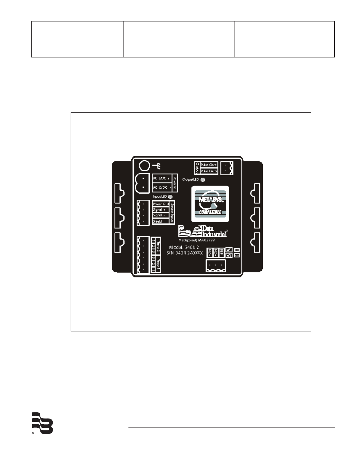
The Series 340N2 transmitter features two LED’s to verify input
and output signals.
The primary output for the Series 340N2 is an isolated solid
state switch closure that is user programmed for units of energy
or ow. The output pulse width is adjustable from 50 mS to 5
sec.
Surface Mount Installation
The Series 340N2 may be mounted to the surface of any panel
using double-sided adhesive tape or by attaching fasteners
through the holes in the mounting anges of the unit.
din rail Mounting
Optional clips snap onto the mounting anges allowing the
Series 340N2 to be attached to DIN 15, 32, 35 mm DIN rail
systems.
Wall Mounting
Optional metal and plastic enclosures are available for the
Series 340N2. The enclosure is rst attached to the wall using
fasteners through its mounting holes.
After wiring, the transmitter may be attached to the enclosure
with the terminal headers facing in using the slots in the Series
mounting anges. As an alternate mounting arrangement, the
340N2 may be fastened to the box cover using double-sided
adhesive tape.
temperature Sensor Installation
The location of the temperature sensors with regard to the ow
sensor is important to the accuracy of the energy calculation.
temperature sensor t1 must be located closest to the
ow sensor. A distance of 5 pipe diameters will give the
greatest accuracy. Always install the temperature sensor
downstream of the ow sensor.
The secondary output is the Johnson Controls N2
communications protocol that allows the Series 340N2 to be
assigned an address and allow all measurement parameters:
inlet and outlet temperature, ow rate, ow total, energy rate
and energy total to be transmitted from as many as 255 units on
a single 3-wire RS-485 bus.
The Series 340N2 Btu transmitter operates on AC or DC power
supplies ranging from 12 to 24 volts.
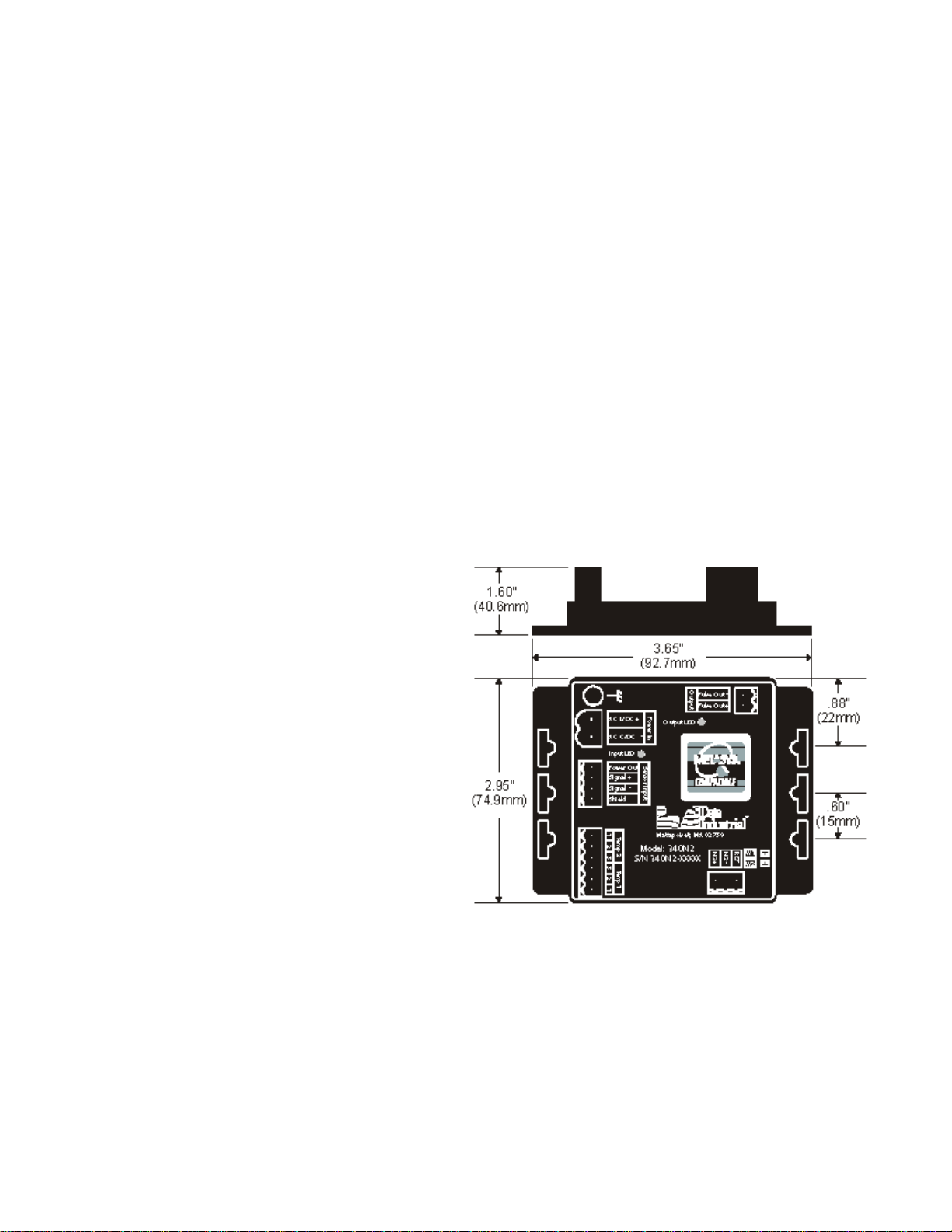
The compact cast epoxy body measures 3.65”(93mm) x
2.95”(75mm) and can be easily mounted in panels, enclosures
or on DIN rails.
InStallatIon
Mechanical Installation
The series 340N2 transmitter may be surface mounted onto a
panel, attached to DIN rails using adapter clips or wall mounted
using optional enclosures.
location
Although the Series 340N2 device is encapsulated, all wiring
connections are made to exposed terminals. The unit should
be protected from weather and moisture in accordance with
electrical codes and standard trade practices.
In any mounting arrangement, the primary concerns are ease of
wiring and attachment of the programming cable.
The unit generates very little heat so no consideration need be
given to cooling or ventilation.
Series 340n2 dimensions
2
Page 3

340n2 Metal Box dimensions
Sensor Wiring
All ow sensor types connect to the four terminal header
labeled “Sensor Input”.
Series 200
Connect the red wire to Series 340N2 Sensor signal (+),
connect the ow sensor black wire to Series 340N2 Sensor
signal (-) and the bare wire to shield.
SdI Series (standard pulse output option)
Connect SDI number 3 sensor signal to the Series 340N2
transmitter sensor signal (+) and the SDI number 2 sensor
common terminal to Series 340N2 transmitter sensor signal
(-). Connect the shield terminal of the SDI sensor to the shield
terminal of the Series 340N2 transmitter.
other Sensors
The Sensor Input power out terminal supplies nominal 12VDC
excitation voltage for 3 wire sensors. Connect sensor signal +
and sensor signal - wires to transmitter terminals.
Note:
The green input LED toggles on and off as sensor pulses
are received. With no ow input the LED will remain in its
last state (either on or off).
340n2 Plastic Box dimensions
Electrical Installation
All connections to the Series 340N2 are made to screw terminals on removable headers.
Power Supply Wiring
The Badger® Series 340N2 requires 12-24 Volts AC or DC to
operate. The power connections are made to the
header. The connections are labeled beside the header.
Observe the polarity shown on the label.
If a Badger Meter plug in type power supply (Model A-1026
or A-503) is used, connect the black/white striped wire to the
terminal marked positive (+) and the black wire to the terminal
marked negative (-).
Note:
Included with every Series 340N2 is a Model 340N2IK kit
containing a screw, lockwasher and ground lead to connect
the Series 340N2 to earth ground. Connect the earth
ground lug of the Series 340N2 to a solid earth ground with
as short a wire as possible. This will help prevent electrical
interference from affecting the Series 340N2’s normal
operation.
oranGE
Side View - Typical Series 300 Removable
connector Wiring
Sample Power Supply Wiring Diagram
3
Page 4

N2+
N2-
REF
2 pmeT
1 pmeT
Model: 340N2
S/N 340N2- XXXX X
W1
W2
FER
2N
-2N+
Mattapoisett, MA 0 273 9
11 22 33
Metasys
®
CPN, FAC,
or NCM
T emp 2
T emp 1
Ma
t
10KΩ Thermistors
Sample Sensor Wiring diagram
temperature Element Wiring
The Badger Meter thermistors are not polarity sensitive.
Connect the thermistor closest to the ow sensor to the Series
340N2 terminal block marked Temp 1 number 3 and number
2. The other thermistor wires to Series 340N2 terminal marked
Temp 2 number 3 and number 2.
Pulse output Wiring
The Badger® Series 340N2 has solid state switch output rated
for a maximum sinking current of 100 mA @ 36 VDC. In
most cases the Series 340N2 pulse out (+) will connect to the
unput pulse (+) and the Series 340N2 pulse out (-) terminal to
the input pulse (-) of the receiving device. The separate two
terminal removable header on the Series 340N2 is labeled
Output. Observe the electrical polarity of the output.
Note:
When the solid state switch is closed the red output LED
will turn on.
connecting the n2 Bus
Observe polarity when connecting the Series 340N2. Connect
the N2+, N2- and Ref to the appropriate connections in the N2
network.
Note:
The Series 340N2 default address must be changed before
it is introduced into an existing network to avoid any pos-
sible address conicts. See programming instructions on
the following page.
Thermistor Wiring Diagram
Sample Pulse Output wiring Diagram
If the Series 340N2 is connected at the beginning or the end of the N2 network, jumpers W1 and W2 can be shorted for
biasing and terminating of the network. The Series 340N2 biasing circuitry is shown in the diagram on the right.
4
Sample wiring to N2 Network
Page 5

Programming the Badger® Series 340n2
Step #1
Select a new N2 address by pressing the
new polling address drop down arrow
Step #2
Press Set Address to select the new
polling address
Step #3
Press Exit to return
to the main screen
Press the Auto Find Address to
search for the Series 340N2
Polling address
Step 1
Press the search button to begin the
search for the Series 340N2 polling
address once an address has been found
press the stop button.
Step 2
Select the detected Series 340N2 address
Step 3
Press the Select button to return to
the N2 polling address window with
the auto find address
Step #1
Press Set Address to select
the new polling address
Step #2
Press Exit to return to the main
screen
To go to the calibration
settings screen select
“parameters” from either
place shown.
Prior to introducing the Badger Series 340N2 onto a N2
network, it needs to be congured for the pipe’s size, desired
units of measure, and its the default network address should
be changed to an unused address to avoid any conicts with
other instruments on the N2 network. Programming the Series
340N2 is accomplished using the Badger Meter PC software.
1. Load the interface software into the computer that was
shipped with the Model A-302 programming cable or download from our website.
2. The Series 340N2 buss connector should be connected to
a Com port using Badger Meter Model A-302 programming
cable. (If not available a B&B Electronics Model 485SD9TB
may be used) The RS232 side should be connected to a
PC Com port and the RS485 side to the Series 340N2.
3. Connect the Series 340N2 transmitter to a power supply.
4. Open the interface software and select the appropriate
Com port as shown in the dialog box below.
5 Select the N2 Protocol as shown below
8. If the Series 340N2 polling address is not known then press
the Auto Find Address button as shown below.
9. Search for the Series 340N2 polling address by following
the steps as shown below.
6. If the Series 340N2 is new from the factory the default
Series 340N2 address is 248. If the selected Series 340N2
address is wrong the unit will not communicate with the
software. To select the correct polling address press the
select button as shown below.
7. If the Series 340N2 has a known address then select it with
the New Polling Address drop down menu as shown below
and press the Set Address button then the exit button.
Proceed to step 11.
10. Then follow the steps as shown below.
11. Open the Parameters Screen as shown below.
12. Program using diagram below as a reference.
13. Set the Series 340N2 address by pressing the Advanced
button in the Parameters window opening the Advanced
Parameters window. Press the Change Device’s Address
button and set as shown below.
5
Page 6

Step 1
see note #1
Select the flow sensor type
(sine or pulse) and enter the
K and Offset -
Step 4
Select the desired flow
rate and total units here
Step 7
Press send to transmit
calibration data to the
Series 340N2
Step 5
Select the desired energy
rate and total units here
Step 2
Select the desired temperature
sensor units.
Step 3
See Note #2
Typically:
Select the method of computing the
temperature differential
T1>T2 for Heating
T1<T2 for Cooling
Step 6
Select the output units per
pulse, and the pulse width
Press to restore the factory default
settings to the screen
must press “send” before values
take effect
Note:
Step 8
Press to exit parameters screen
and to go back to main screen
Press to refresh the parameters screen with
current Series 340N2 settings
Will overwrite any changes not sent to Series 340N2.
See Note #3
Step 1
Select a new device address using the
New Device Address pull down box.
Step 2
Press the Set New Device Address
button to send a new N2 address to
the Series 340N2.
Step 3
Press the Exit button to return
to the Parameters screen
Note #1:
Badger Meter sensors are pulse type sensors. The K and
Offset information is printed in the owners manual shipped with
the product. This information is also available on our website.
Calibration constants for other sensors must be supplied by the
manufacturer.
Note #2
Typically the temperature measured by T1 will be greater
than T2 in a heating application and less than T2 in a cooling
application. The selection of one of these choices will determine
if energy calculations are made for heating only (T1>T2),
cooling only (T1<T2), or both (absolute).
Note #3
The lter coefcient screen allows adjustment of the ow and
energy lters. A scale of 0-10 is used with 10 providing the
greatest degree of smoothing. Settings greater then “10” are
permitted by selecting other. However, settings greater then
“10” should be used with extreme caution as it will cause the
Series 340N2 to respond very slowly to actual changes in ow
and energy. This could cause misreporting of fast changing ow
and energy consumption data. See the dialog box below.
6
Page 7

®
340N2 Point Map
NPT
1
NPA
2
UNITS POINT DESCRIPTION RANGE / VALUENOTES
binary output (2:4)
BO 01 n/aReset Total 1 = reset totals Note 1
float data (1:5, 2:5)
ADF01gpm * (flow rate
conv coeff)
Flow Rate 0-max float
ADF 02 gallons * (flow
total conv coeff)
Flow Total 0-((2^32)-1)
ADF03kBtu/hr *
(energy rate
conv coeff)
Energy Rate 0-max float
ADF04Btu * (energy
total conv coeff)
Energy Total 0-((2^32)-1)
ADF05°F or °C Temp1
ADF06°F or °C Temp2
ADF07n/a Flow Rate Conversion Coefficient 0-max float
ADF08n/a Flow Total Conversion Coefficient 0-max float
ADF09n/a Energy Rate Conversion Coefficient 0-max float
ADF0An/a Energy Total Conversion Coefficient 0-max float
integer data (1:6, 2:6)
ADI01n/a Temperature Units (0-1)Note 2
Note 1: This point resets flow and energy totals when sent an override of value 1. It will
recognize this command, but keep a value of 0 always.
Note 2: 0 = Fahrenheit, 1 = Centigrade
1
Network Point Type
2
Network Point Address
Metasys
To incorporate point data into the Metasys Network and the Metasys Companion Network the following Point Map is provided
Network Setup
Series 340n2 Point Map
Badger Meter, Inc. has decided not to implement the change
of state feature in our Badger® Series 340N2 Btu transmitter.
By our decision not to use this feature, normal Metasys COS
(alarm limits for analog values and normal condition for binary)
notication will be defeated. If COS notication is required, it is
necessary for the operator to perform the following:
1) Map the specic object(s) requiring COS to a CS
object.
2) Dene an AD or BD object with the CS object of
the required COS point, as the associated in.
3) Assign alarm limits to the AD.
4) The AD or BD point will only be scanned at a
5) The normal state of the BO must be updated
Analog/binary input points that are mapped in directly that do
not support COS will never report a change of state condition.
They will report the current value when read, but no alarm
notication will occur. A read will only occur if a focus window is
open or a feature requires the current value.
minimum of 30 seconds.
(written to) by GPL.
7
Page 8

SPEcIFIcatIonS
Power
Power supply options:
12-35 VDC +/- 5%
12-24 VAC +/- 10%
Current Draw:
60 mA @ 12 VDC
n2 output
RS-485 output compliant with
EIA / TIA - 485 standards
operating temperature
-29° C to +70° C
-20° F to +158° F
Flow Sensor Input
All sensors:
Excitation voltage 3 wire sensors:
7.9 – 11.4 VDC 270W source impedance
Pulse type sensors:
Signal amplitude:
2.5 VDC threshold
Signal limits:
Vin < 35V (DC or AC peak)
Frequency:
0-10kHz
Pull-up:
2 kW
Sine wave sensors:
Signal amplitude:
10 mV p-p threshold
Signal limits:
Vin < 35V (DC or AC peak)
Frequency:
0-10kHz
temperature Sensor Input
2 required:
10 kW thermistor, 2 wire, type II, 10 kW @ 25°C
Pulse output
Opto-isolated solid state switch
Operating Voltage range:
0 - ±60V (DC or AC peak)
Closed (on) state:
Load Current - 700mA max. over operating temperature
range
On-resistance - 700mW max. over operating temperature
range
Open (off) state – leakage @ 70°C
<1µA @ 60V (DC or AC peak)
Storage temperature
-40° C to +85° C
-40° F to +185° F
Weight
4.8 oz. with headers installed
SEnSor calIBratIon
Badger Meter
Use K and Offset provided in sensor owner’s manual
other Sensors
Check with factory
unItS oF MEaSurE
Flow measurement
Rate:
gpm, gph, l/sec, l/min, l/hr, ft3/sec, ft3/min, ft3/hr, m3/sec,
m3/min, m3/hr
Total:
gallons, liters, cubic feet, cubic meters
Energy measurement
Rate
kBtu/min, kBtu/hr, kW, MW, hp, tons
Total
Btu, kBtu, MBtu, kWh, MWh, kJ, MJ
temperature units
Fahrenheit, Centigrade
ProGraMMInG
Requires PC or laptop running Windows
®
XP or Vista
Badger Meter Model A-302-20 programming kit containing
software and Model A302-20 programming cable
8
Page 9

FACTORY DEFAULTS
Default Values Customer Values
Serial Number n/a
Version n/a
Temperature Units °F
Sensor Type Pulse
K= 1
Offset= 0
Flow Rate Units gpm
Flow Total Units gallons
Energy Rate Units kBtu/hr
Energy Total Units Btu
Energy Calculation absolute
Flow Filter 0
Energy Filter 0
Scaled Pulse Output Units energy
Scaled Pulse Output Units Per Pulse 1
Scaled Pulse Output Pulse Width 100
9
Page 10

10
Page 11

(This page intentionally left blank.)
11
Page 12

(This page intentionally left blank.)
Badger® and Data Industrial® are registered trademarks of Badger Meter, Inc.
Metasys® is a registered trademark of Johnson Controls.
Windows® is a registered trademark of Microsoft Corporation.
Please see our website at www.badgermeter.com
for specific contacts.
Copyright © Badger Meter, Inc. 2009. All rights reserved.
Due to continuous research, product improvements and enhancements, Badger
Meter reserves the right to change product or system specifications without notice,
except to the extent an outstanding contractual obligation exists.
BadgerMeter, Inc.
6116 E. 15th Street, Tulsa, Oklahoma 74112
(918) 836-8411 / Fax: (918) 832-9962
www.badgermeter.com
 Loading...