

Page 1
Badger
®
Series 340LW
Btu Transmitter
With LONWORKS
Installation &
®
Operation Manual
BadgerMeter, Inc.
872038
Rev. 6 4-09
Page 2

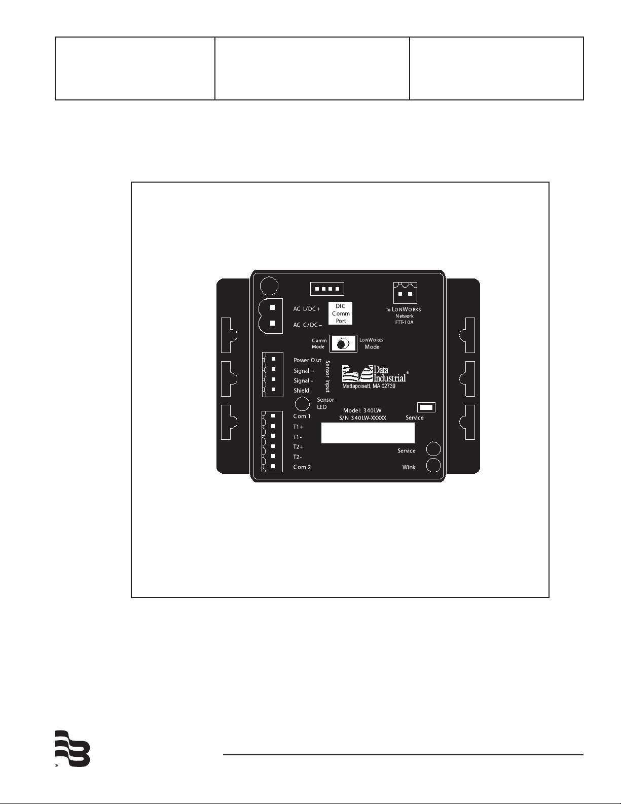
The Badger Meter Series 340LW Btu Transmitter is an economical, compact device for submetering applications that use the LONWORKS® protocol in an addressable network.
The Series 340LW calculates thermal energy using the signal from a fl ow sensor installed in
a closed pipe system, and the signals from two 10kΩ temperature thermistors installed in the
systems inlet and outlet points. The fl ow input may be provided by any Badger Meter sensor and
many other pulse or sine wave signal fl ow sensors.
The onboard microcontroller and digital circuitry make precise measurements and produce
accurate, drift-free outputs. The Series 340LW is commissioned using Badger Meter Windows®
based software. Calibration information for the fl ow sensor, units of measurement and output
scaling may be preselected or entered in the fi eld. While the unit is connected to a PC or laptop
computer, real-time fl ow rate and total, temperatures and energy rate and total are available.
The Series 340LW Transmitter features three LED’s to verify input and output signals.
The LONWORKS communications protocol allows the Series 340LW to be assigned to any one
of 255 addresses on a single 2-wire buss. Outputs may include raw data such as fl ow rate and
temperature of either thermistor, or computed or stored data such as: energy rate; energy total;
fl ow total; or temperature differential.
The Series 340LW Btu Transmitter operates on AC or DC power supplies ranging from 12 to 24
volts.
The compact cast epoxy body measures 3.65 inch (93mm) x 2.95 inch (75mm) and can be easily
mounted on panels, DIN rails or enclosures.
2
Page 3
INSTALLATION
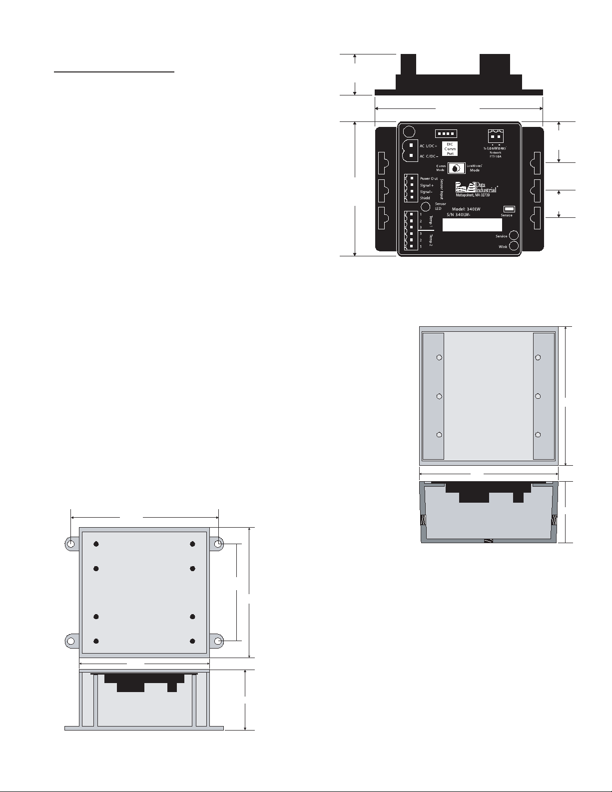
2.10”
(53.3mm)
3.65”
(92.7mm)
2.95”
(74.9mm)
.88”
(22mm)
.60”
(15mm)
Mechanical installation
The Badger® Series 340LW transmitter may be surface mounted onto a panel, attached to DIN rails using
adapter clips or wall mounted using two optional enclosures.
Location
Although the Series 340LW device is encapsulated, all
wiring connections are made to exposed terminals. The
unit should be protected from weather and moisture in
accordance with electrical codes and standard trade
practices. In any mounting arrangement, the primary
concerns are ease of wiring and attachment of the
programming cable. The unit generates very little
heat so no consideration need be given to cooling or
ventilation.
Series 340LW Dimensions
Surface Mount Installation
The Series 340LW may be mounted to the surface of any panel using
double-sided adhesive tape or by attaching fasteners through the holes
in the mounting flanges of the unit.
Din Rail Mounting
Optional clips snap onto the mounting flanges allowing the Series
340LW to be attached to DIN 15, 32, 35 mm DIN rail systems.
5.125”
3.25”
To p
4.60”
Wall Mounting
4.60”
Side
Optional metal and plastic enclosures are available to mount
the Series 340LW to a wall when no other enclosure is used.
The enclosure is first attached to the wall using fasteners
through its mounting holes. After wiring, the transmitter may
be attached to the enclosure with the terminal headers fac-
2.25”
Side
ing in using the slots in the mounting flanges. As an alternate
mounting arrangement, the Series 340LW may be fastened to
340LW Plastic Box Dimensions
To p
4.5”
Side
Side
340LW Metal Box Dimen-
sions
4.50”
2.00”
3
Page 4
the box cover using double-sided adhesive tape.
Temperature Sensor Installation
The location of the temperature sensors with regard to the flow
sensor is important for the accuracy of the energy calculation.
Temperature sensor T1 must be located closest to the flow sensor.
A distance of 5 pipe diameters will give the greatest accuracy.
Always install the temperature sensor downstream of the flow
sensor.
3/32” Flathead
Screwdriver
Wire
Series 300
Connector
Electrical Installation
All connections to the Badger® Series 340LW are made to screw
terminals on removable headers.
Side View - Typical 300 Series Removable Connector
Wiring
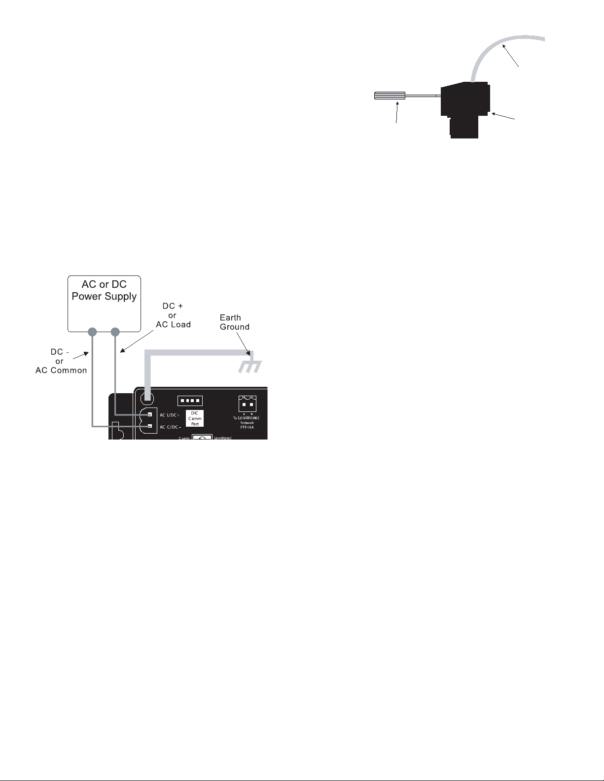
Power Supply Wiring
The Series 340LW requires 12-24 Volts AC or DC to operate. The power connections are made to the
ORANGE header. The connections are labeled beside the header. Observe the polarity shown on the label.
When powered with AC power provided by a
transformer secondary the Series 340LW causes DC
current to fl ow in the transformer secondary. When
several Series 340LWs are powered in parallel by the
same transformer secondary, the currents will add and
a suffi cient secondary DC current may fl ow to cause
transformer core saturation. Improper operation may
result.
When powering multiple Series 340LWs, a DC
power supply with appropriate output capability should
be used to prevent this situation. For instance, Sixteen
Series 340LWs will require 16 x 70mA = 1120mA. A 1.5
Amp, 12-24 Volt DC power supply would handle such a
load.
When operating a Series 340LW from AC
Sample Power Supply Wiring Diagram
power, one side of the AC voltage source should be
grounded to earth ground. This grounded AC source side should be connected to the Series 340LW “ACC/
DC-” power input terminal, the other side being connected to the Series 340LW “ACL/DC+” terminal. (This
arrangement is like that in normal 110 VAC power, which has a “neutral” or common side and a “hot” or line
side.
For optimal noise immunity and when operating the Series 340LW with a “zero threshold, sine
wave” fl ow sensor, the ground lug on the Series 340LW should be connected to earth ground.
If a Badger Meter plug in type power supply (Model A-1026 or A-503) is used, connect the black/white
striped wire to the terminal marked positive (+) and the black wire to the terminal marked negative (-).
Note:
Included with every Series 340LW is a Model 340LWIK kit containing a screw,
lockwasher and ground lead to connect the Series 340LW to earth ground. Connect
the earth ground lug of the series 340LW to a solid earth ground with as short a wire
as possible. This will help prevent electrical interference from affecting the Series
340LW’s normal operation.
4
Page 5
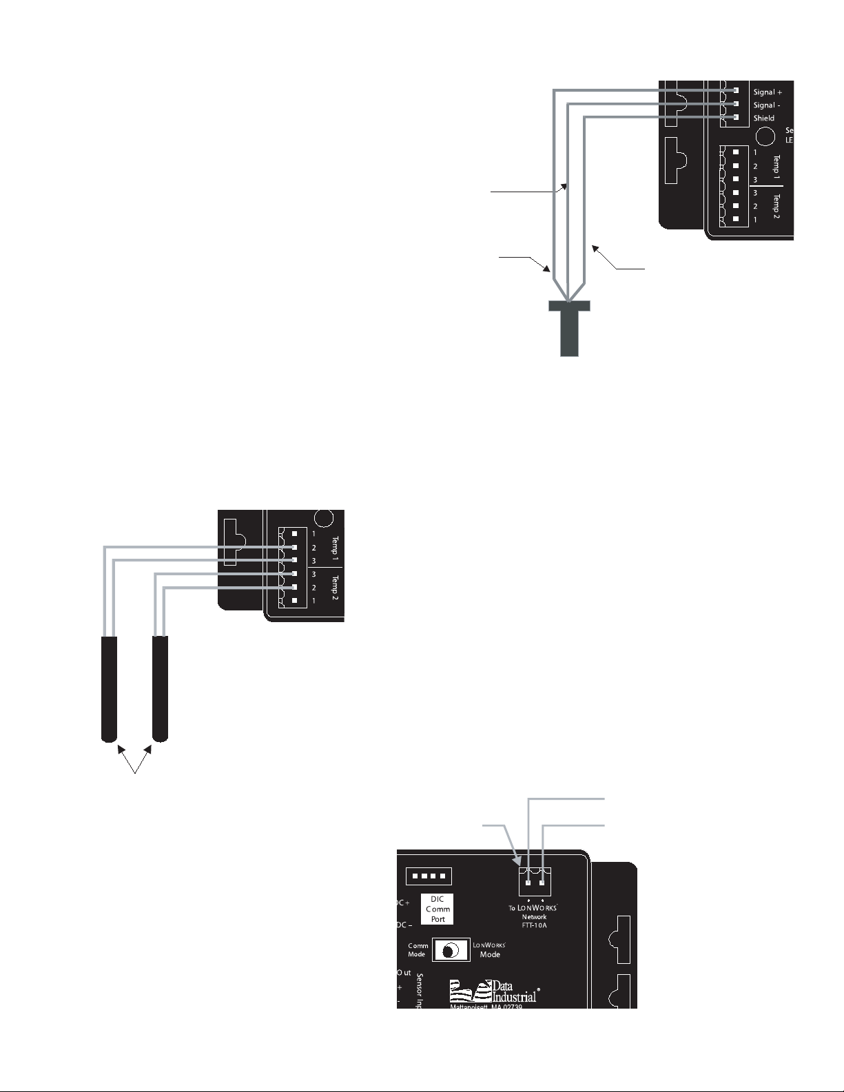
Sensor Wiring
10KΩ Thermistors
Supply
Return
To O N OR K S
Network
LW
®
Not Polarity
Sensitive
Red
Black
Shield
(if applicable)
Series 200
or
SDI
All flow sensor types connect to the four terminal
header labeled “sensor input”.
Series 200
Connect the red wire to sensor signal (+), black wire
to sensor signal (-) and the bare wire to shield.
SDI Series
Connect the plus (+) terminal of the sensor to
sensor signal (+) on the transmitter and the minus
(-) terminal of the sensor to sensor signal (-) on the
transmitter. Connect the shield terminal of the sensor
to the shield terminal of the transmitter.
Other Sensors
The sensor input Power Out terminal supplies
nominal 12VDC excitation voltage for 3 wire sensors.
Sample Sensor Wiring Diagram
Connect sensor signal + and sensor signal - wires to transmitter terminals.
Thermistor Wiring Diagram
Temperature Element Wiring
The Badger Meter thermistors are not polarity sensitive.
Connect thermistor closest to the flow sensor to Series 340
terminal block marked TEMP 1 and the other thermistor wires to
Series 340 terminal marked TEMP 2.
Connecting the L
ONWORKS
®
Bus
The LONWORKS network connection is not polarity sensitive.
Refer to”commissioning” section
5
Page 6

Programming in Comm Mode
Programming the Badger
®
Series 340LW is accomplished by installing the Badger Meter programming
software on a computer and entering data on templates of the Windows® based program.
1. Load the interface software into the computer.
2. Connect the computer to the Series 340 transmitter with the Badger Meter Model A-301 communications cable to the socket labeled COMM PORT, taking care to properly align the tab on the plug
and socket to maintain polarity. Connect the DB9 connector of the Badger Meter Model A301 communications cable to a PC com port that has the Series 340 software installed.
3. Move the Protocol Switch to the Comm Mode.
4. Connect the Series 340 transmitter to a power supply.
5. Open the interface software and select the appropriate COMM PORT as shown in the dialog box
below.
6. Open the Parameters Screen as shown below.
To go to the calibration
settings screen select
“parameters” from either
place shown
Programming in Comm Mode
Step 7
When programming is complete, be sure to return the “Comm Mode/LonWorks Mode” Switch to the
LonWorks Mode position.
6
Page 7

8. Program using diagram below as a reference.
Step 1
Select the flow sensor type
(sine or pulse) and enter the
K and Offset -
see note #1
Step 4
Select the desired flow
rate and total units here
(see special note #2)
Step 7
Press send to transmit
calibration data to the
Series340
Step 2
Select the desired temperature
sensor units
Step 3
Select the method of computing the
temperature differential
Typically:
T1>T2 for Heating
T1<T2 for Cooling
Step 5
Select the desired energy
rate and total units here
(see special note #2)
Step 6
Select the output units per
pulse, and the pulse width
Step 8
Press to exit parameters screen
and to go back to main screen
see note #2
Press to refresh the parameters screen with
the current 430 settings.
See Note #3
Press to restore the factory
default settings to the screen
Note: Must press “send” before
values take effect.
Note #1:
Badger Meter flow sensor K and Offset information is printed in the flow sensor owners manual,
and also available on our website. Calibration constants for other sensors must be supplied by the
manufacturer.
Note #2
Typically the Temperature measured by T1 will be greater than T2 in a heating application and
less than T2 in a cooling application. The selection of one of these choices will determine if energy
calculations are made for heating only (T1>T2), cooling only (T1<T2), or both (absolute).
Note #3
The filter coefficient screen allows adjustment of the flow and energy filters. A scale of 0-10 is used
with 10 providing the greatest degree of smoothing. See the dialog box below.
7
Page 8

Commisioning:
Object #0 - Node Object
Object #1 - Flow Object
Object #2 - Energy Object
Object #3 - Temperature Object
Object #4 - Comm Status
Outputs
Outputs
Outputs
Outputs
Outputs
Inputs
Series 340 LonWorks
LonMark Implementation
Series 340 LonWorks
Interface Overview
Before the Badger® Series 340LW can be used on the LonWorks network, a network tool must commission it.
The 340 LW has a red “Wink” LED and a green “Service” LED.
The green “Service” LED has is used to report the commission status.
If commissioned, on power-up the green LED turn ON for a few seconds, and then turn off.
If not commissioned the green LED will flash at about a ½ Hz rate.
If the LED turns ON, then OFF, and then ON steady, contact the factory.
Special notes for operation
1. comm status
=0 - booted up, no comm with internal uart
=1 - connected to internal uart
=2 - LONWORKS® mode
=3 - commode
2. units that must be set by the 340 PC software for this software revisions to work properly
gpm
gallons
kbtu/hr
btu
3. all configuration properties (CPs) are set to ten second updates for each outgoing measurement network variable,
can be modified via LonMaker browser
4. internal measurement readings are updated every ten seconds (this update rate is not changeable)
5. to reset total, send the following to nvi00Request in the LonMaker browser
“1,RQ_OVERRIDE”
“2,RQ_OVERRIDE”
either of the above will reset both flow total and energy total
8
Page 9

nvi00Request types:
RQ_NORMAL: for measurement
Objects #1 - 3, updates SNVTs with
latest value read from Series 340
RQ_OVERRIDE: for Objects #1
or #2, resets all totals, should be
used with authentication to
prevent tampering.
Node Object #0
(Object Type #0)
nvi00Request
SNVT_obj_request
nvo00Status
SNVT_obj_request
Mandatory NVs
nv1 nv2
Flow Object #1
(Object Type #1)
Mandatory NVs
nvo01FlowRate
SNVT_flow_f
nv1
Optional
Configuration
Properties
nc22 nciFlRtMaxSendT
SNVT_elapsed_tm
nvo02FlowTot_f
SNVT_vol_f
nv2
nc22
nciFlTotFMaxSendT
SNVT_elapsed_tm
nvo03FlowTot_k
SNVT_vol_kilo
nv3
nc22
nciFlTotKMaxSendT
SNVT_elapsed_tm
9
Page 10

Energy Object #2
(Object Type #1)
nc22
nciEnRtMaxSendT
SNVT_elapsed_tm
nvo04EnergyRate
nv1
nv2
nv3
nv4
SNVT_power_f
nvo05EnergyTot_f
nvo06EnergyTot_k
SNVT_btu_kilo
nvo07EnergyTot_M
SNVT_btu_mega
Mandatory NVs
SNVT_btu_f
Optional
Configuration
Properties
nc22
nc22
nc22
nciEnTotFMaxSendT
SNVT_elapsed_tm
nciEnTotKMaxSendT
SNVT_elapsed_tm
nciEnTotMMaxSendT
SNVT_elapsed_tm
Temperature Object #3
(Object Type #1)
nv1
nv2
nv1
nv3
Mandatory NVs
nvo08Temp1
SNVT_temp_f
nvo09Temp2
SNVT_temp_f
nvo10DeltaT
SNVT_temp_f
10
nc22
nc22
nc22
Optional
Configuration
Properties
nciT1MaxSendT
SNVT_elapsed_tm
nciT2MaxSendT
SNVT_elapsed_tm
nciDeltaTMaxSendT
SNVT_elapsed_tm
Page 11

Communications Status
Object #4
(Object Type #1)
Mandatory NVs
nv1
output SNVT types:
flow rate -> SNVT_flow_f -1E38 .. 1E38 I/sec
flow total -> SNVT_vol_f 0 .. 1E38 liter
SNVT_vol_kilo 0 .. 6,553.5 kiloliters (0.1 lk)
energy rate -> SNVT_power_f -1E38 .. 1E38 watts
energy total -> Energy, thermal -> SNVT_btu_f 0 .. 1E38 btu
SNVT)btu_kilo 0 .. 65,535 kilo btu
SNVT_btu_mega 0 .. 65,535 mega btu
nvo11CommStatus
SNVT_count
temps (temp1, temp2, delta T)->
SNVT_temp_f -273.17 .. 1E38ºC
11
Page 12

SPECIFICATIONS
Power
Power supply options:
12-35 VDC +/- 5%
12-24 VAC +/- 10%
Current Draw:
60 mA @ 12 VDC
Flow Sensor Input
All sensors:
Excitation voltage 3 wire sensors:
7.9 – 11.4 VDC 270Ω source
impedance
Pulse type sensors:
Signal amplitude:
2.5 VDC threshold
Signal limits:
Vin < 35V (DC or AC peak)
Frequency:
0-10kHz
Pull-up:
2 kΩ
Sine wave sensors:
Signal amplitude:
10 mV p-p threshold
Signal limits:
Vin < 35V (DC or AC peak)
Frequency:
0-10kHz
Temperature Sensor Input
2 required:
10 kΩ thermistor, 2 wire, type II, 10 kΩ @
25°C
Operating Temperature
-29° C to +70° C
-20° F to +158° F
Storage Temperature
-40° C to +85° C
-40° F to +185° F
Weight
4.8 oz. with headers installed
SENSOR CALIBRATION
Badger Meter
Use K and Offset provided in sensor owner’s
manual
Other Sensors
Check with factory
UNITS OF MEASURE
Measurement Outputs
Transmitted in SI units
Flow
Rate and total
Energy
Rate and total
Temperature
PROGRAMMING
®
Requires PC or laptop running Windows
XP or
Vista
Badger Meter Model A-340LW programming
kit containing software and Model A301
programming cable
12
Page 13

FACTORY DEFAULTS
Default Values Customer Values
Serial Number n/a
Version n/a
Temperature Units °F
Sensor Type Pulse
K= 1
Offset= 0
Flow Rate Units gpm
Flow Total Units gallons
Energy Rate Units kBtu/hr
Energy Total Units Btu
Energy Calculation absolute
Flow Filter 0
Energy Filter 0
Scaled Pulse Output Units energy
Scaled Pulse Output Units Per Pulse 1
Scaled Pulse Output Pulse Width 100
13
Page 14

(This page intentionally left blank)
15
Page 15

Badger® and Data Industrial® are registered trademarks of Badger Meter, Inc.
Windows® is a registered trademark of the Microsoft Corporation.
LonWorks® is a registered trademark of Echelon Corporation.
Due to continuous research, product improvements and enhancements, Badger
Meter reserves the right to change product or system specifications without notice,
except to the extent an outstanding contractual obligation exists.
Please see our website at www.badgermeter.com
for specific contacts.
Copyright © Badger Meter, Inc. 2009. All rights reserved.
BadgerMeter, Inc.
P.O. Box 581390, Tulsa, Oklahoma 74158
(918) 836-8411 / Fax: (918) 832-9962
www.badgermeter.com
 Loading...