

Page 1
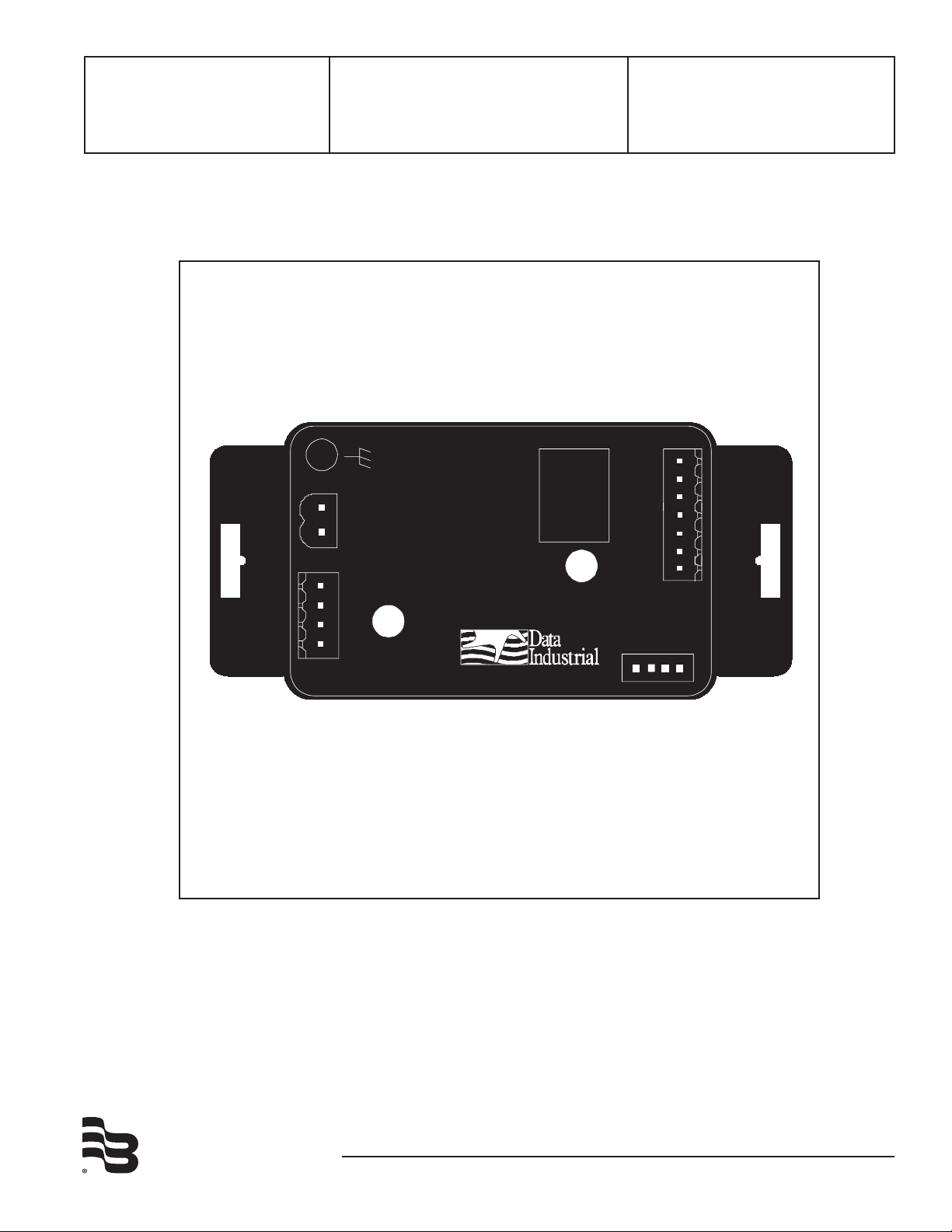
Badger® Series 330
®
Industrial
Power Out
(+)
(-)
Shield
AC Load/DC +
AC Common/DC -
DIC Comm.
Port
Output
Input
®
Model: 330
SN# 0000000
N.O.
ComA
N.C.
ComB
Hi
Com
Low
Programmable - Set-Point
Relay Control
Installation &
Operation Manual
BadgerMeter, Inc.
872039
Rev. 6
4-09
Page 2
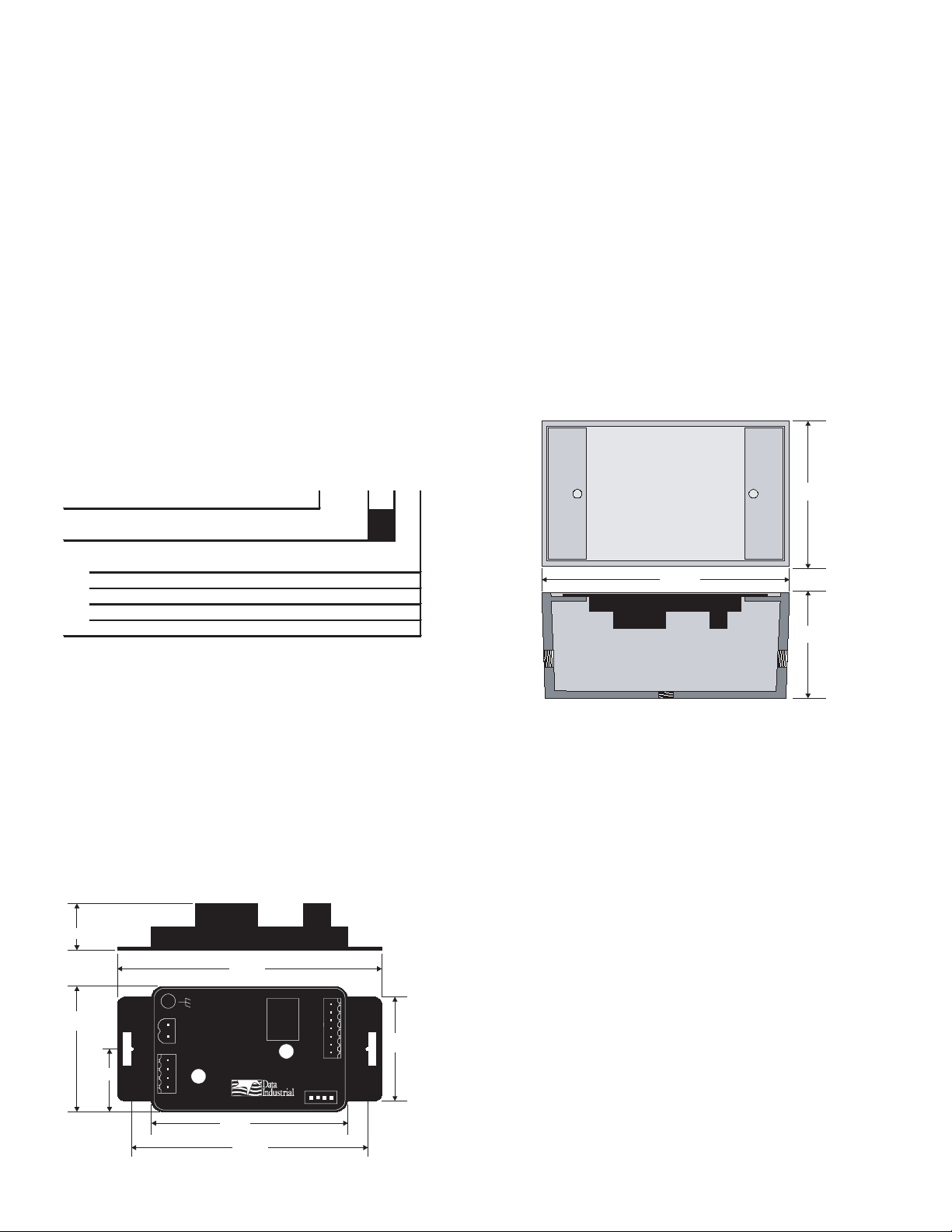
1.50”
3.65”
3.25”
.875”
1.75”
Side
1.50”
2.75”
®
Industrial
Power
(+)
(-)
Shield
AC Load/DC +
AC Common/DC -
DIC Comm.
Port
Output
Input
®
Model: 330
SN# 0000000
NO1
NO2
NC1
NC2
Hi
Com
Lo
The Badger® Series 330 is a compact, programmable relay
EXAMPLE:
330 - xx
Series
Programmable Local Relay Control
330
Options
Transmitter Only
00
W / NEMA 4X Enclosure
01
W / Metal Enclosure 02
W / Plastic Enclosure 03
W / DIN Rail Mounting Clips 04
Series 330 Ordering Matrix
Side
4.5”
2.8”
2.0”
TOP
SIDE
control capable of converting the signal from a Badger Meter
flow sensor into a flow switch.
any panel using double sided adhesive tape or by attaching
fasteners through the holes in the mounting flanges of the
unit.
With an onboard microcontroller and digital circuitry, the
Badger Series 330 is programmed from a Windows® based
computer program. This eliminates the need to set dip
switches or potentiometers and produces precise, accurate
and drift free control of the relay outputs. In addition to
accepting the Badger Meter square wave signal, the Badger
Series 330 can accept other pulse and sine wave inputs.
The compact cast epoxy body measures 1.75” (44mm) x
2.75” (70mm) x 1.5” (38mm) and can easily be mounted to
panels, DIN rails or enclosures. With multiple inputs, ease of
use and a variety of enclosures, the Badger Series 330 is a
powerful, competitive priced relay control.
INStallatION
Mechanical installation
The Badger Series 330 transmitter may be surface mounted
onto a panel, attached to DIN rails using adapter clips or wall
mounted using two optional enclosures.
Series 330 Ordering Matrix
DIN Rail Mounting
Optional clips snap onto the mounting flanges allowing the
Series 330 to be attached to DIN 15, 32, 35 mm DIN rail
systems.
Wall Mounting
Optional metal and plastic enclosures are available to mount
the Badger Series 330 to a wall when no other enclosure is
used. The enclosure is first attached to the wall using fasteners through its mounting holes.
After wiring, the transmitter may be attached to the enclosure with the terminal headers facing in using the slots in
the mounting flanges. As an alternate mounting arrangement, the Series 330 may be fastened to the box cover using
double-sided adhesive tape.
location
Although the Badger Series 330 device is encapsulated,
all wiring connections are made to exposed terminals.
The unit should be protected from weather and moisture
in accordance with electrical codes and standard trade
practices.
In any mounting arrangement, the primary concerns are
ease of wiring and attachment of the programming cable.
The unit generates very little heat so no consideration need
be given to cooling or ventilation.
Surface Mount Installation
The Badger Series 330 may be mounted to the surface of
2
Series 330 Dimensions
Series 330 Optional Enclosure Dimensions
Electrical Installation
All connections to the Badger Series 330 are made to screw
terminals on removable headers.
Power Supply Wiring
The Badger Series 330 requires 12-24 Volts AC or DC to
operate. The power connections are made to the ORANGE
header. The connections are labeled beside the header.
Observe the polarity shown on the label.
If a Badger Meter plug in type power supply
(Model A-1026 or A-503) is used to connect the black/white
striped wire to the terminal marked positive (+) and the black
wire to the terminal marked negative (-).
Page 3
®
Industrial
AC Load/DC +
AC Common/DC -
N.O.
ComA
N.C.
ComB
Hi
GND
Low
DC +
or
AC Load
DC -
or
AC Common
Earth
Ground
AC or DC
Power Supply
3/32” Flathead
Screwdriver
Series 300
Connector
Wire
Note:
®
Industrial
Power
(+)
(-)
Shield
AC Load/DC +
AC Common/DC -
DIC Comm.
Port
Output
Input
®
Model: 330
SN# 0000000
N.O.
ComA
N.C.
ComB
Hi
GND
Low
Red
Black
Shield
(if applicable)
Series 200
or
SDI
NO1
NO2
NC1
NC2
Hi
Com
Lo
Remote Reset
NO1
NO2
NC1
NC2
Hi
Com
Lo
Relay
Included with every Series 330 is a Series 330IK kit
containing a screw, lock washer and ground lead to
connect the Series 330 to earth ground. This will help
prevent electrical interference from affecting the Series
330’s normal operation.
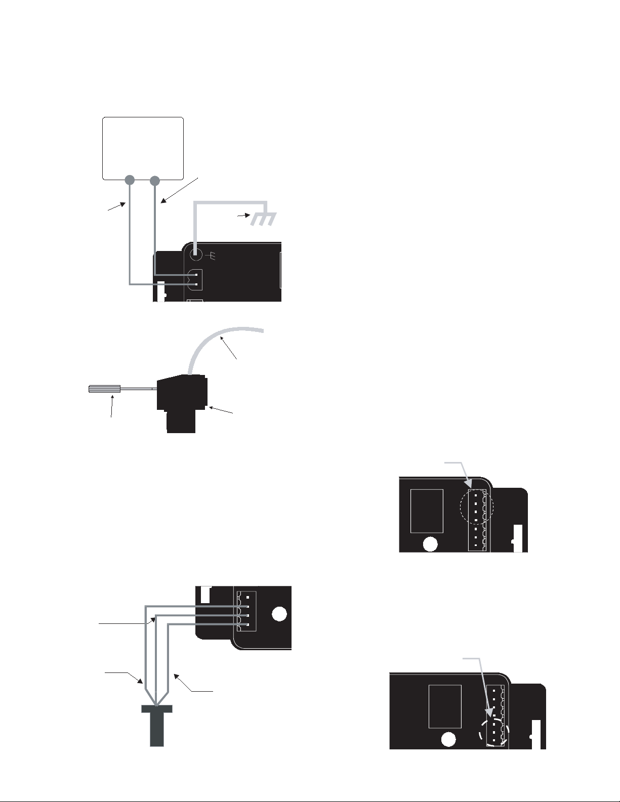
Sample Power Supply Wiring Diagram
(-) on the Badger Series 330.
3) Connect the Bare wire (if applicable) of the sensor to
the Shield terminal on the Series 330.
If sensor is a Badger Series 4000 then:
1) Connect the red wire of the Series 4000 to Power on
the Series 330.
2) Connect the black wire of the Series 4000 to the
Sensor (-) on the Series 330.
3) Connect the clear wire of the Series 4000 to the
Sensor (+) on the Series 330.
4) Connect the bare wire of the Series 4000 to the Shield
on the Series 330.
If sensor is a SDI Series with standard frequency (pulse)
output then:
1) Connect terminal 3 (sensor signal) of the SDI to
Sensor (+) on the Badger Series 330.
2) Connect terminal 2 (sensor common) of the SDI to
Sensor (-) on the Series 330.
3) Connect the terminal 1 (shield) of the SDI to the Shield
on the Series 330.
If sensor is a Non Badger Meter Flow Sensor:
The sensor input power terminal supplies nominal 9.1VDC
excitation voltage for 3 wire sensors. Connect sensor signal
+ and sensor signal - wires to transmitter terminals.
Side View - typical Series 300
Removable Connector Wiring
Sensor Wiring
All flow sensor types connect to the four terminal header
shown in the “sample sensor wiring diagram.”
If sensor is a Badger
®
Series 200 then:
1) Connect the Red Wire of the sensor to Sensor signal
(+) on the Badger Series 330.
2) Connect the Black wire of the sensor to Sensor signal
Relay Output Wiring
The Badger Series 330 is supplied with a removable DPST
relay with normally open and normally closed contacts. To
wire to the normally closed contacts connect to the terminals
“NC1” and “NC2”. To wire to the normally open contacts
connect to the terminals “NO1” and “NO2”. Note: this relay
may be used as a Form C relay. Use a jumper to connect
one terminal from each set together as the common
terminal.
Relay Location
Remote Reset Switch Wiring (if applicable)
The “Hi”, “Com”, and “Lo” terminals on the Badger Series
330 are used for a remote reset. If the remote reset device
provides a momentary dry contact closure - then connect
to the “Lo” and “Com” terminals. If the remote reset device
provides a momentary voltage (up to the supply voltage to
the Series 330) - then connect to the “Hi” terminal.
Sample Sensor Wiring Diagram
Remote Reset Location
3
Page 4

Communications Cable Wiring
DIC Com port
®
Industrial
DIC Comm.
Port
®
N.O.
ComA
N.C.
ComB
Hi
GND
Low
Field calibration requires a Badger Meter Series A330
Programming kit (consisting of a custom cable and software)
and a PC running Windows® XP or Vista. In order to
program, the Badger® Series 330 must be connected to
power, and the Series A301 cable must be connected to the
Series 330 Com port connector and an available 9-pin Com
port on a computer.
Note:
The Badger Meter Series A301 Cable will work with all
Series 300 products. However the older version of the
cable (A300) does not have sufficient bandwidth to work
with the Series 340 transmitters.
Badger Meter provides free programming software updates
via the Internet for all Badger Series 300 devices. Go to
www.badgermeter.com for these updates.
DEFINItIONS:
High alarm – A condition where if the flow rate exceeds
the set point the relay is energized.
low alarm - A condition where if the flow rate drops below
the set point the relay is energized.
Set Point – The flow rate that will trigger the event. (i.e.
energize the relay).
Release Point – The flow rate that will de-energize the relay.
Set Point Delay – A time interval in seconds between the
point when the flow rate crosses the set point and the relay
energizes.
Release Point Delay - A time interval in seconds between
the point when the flow rate crosses the release point and
the relay de-energizes.
latch – A function that will hold the relay in the energized
state until reset even if the flow rate crosses the release
point.
Remote Reset - Reset is the ability to interrupt all timing
functions and return them to the initial programmed settings
and/or de-energize the relay coil that has been latched as a
result of an alarm function.
Location of the
DIC Com port
PROgRaMMINg
Programming the Badger Series 330 is accomplished by
installing the Badger Meter programming software on a
computer and entering data on templates of the Windows®
based program.
1. Load the interface software into the computer.
2. Connect the computer to the Series 330 transmitter with
the Badger Meter Model A-301 communications cable
to the socket labeled “D.I.C Com port”, taking care to
properly align the tab on the plug and socket to maintain polarity. Connect the DB9 connector of the Badger
Meter Model A301 communications cable to a PC Com
port that has the Series 330 software installed.
3. Connect the Series 330 transmitter to a power supply.
4. Open the interface software and select the appropriate
Com port as shown in the dialog box below.
This reset may be accomplished by momentarily
disconnecting the power supply or connecting an external
device to the reset terminals.
Filter Coefficient - An averaging routine that smooths out
unstable flow. The non-linear reference scale from 0-9
defaults to a value of 2. Do not change unless flow changes
interfere with the control functions.
6. Program using the diagram below as a reference.
5. Open the Parameters Screen as shown below.
4
Page 5

SPECIFICATIONS
Power
Power Supply Options
12-36 VDC (+/- 10%)
12-26 VAC (+/- 10%)
Current Draw
60 mA @ 12 VDC
FLOw SENSOR INPuT
All Sensors
Excitation voltage 3 wire sensors:
9.1 VDC 500Ω source
impedance
Pulse Type Sensors
Signal Amplitude
2.5 VDC threshold
Signal Limits
Vin < 35V (DC or AC peak)
Frequency
0-10kHz
Pull-up
2 kΩ
Sine wave Sensors
Signal Amplitude
10 mV p-p threshold
Signal Limits
Vin < 35V (DC or AC peak)
Frequency:
0-10kHz
SENSOR CALIBRATION
Badger Meter
Use K and Offset provided in sensor owner’s manual
Other Sensors
Check with factory
uNITS OF MEASuRE
Flow Measurement Rate
gpm, gph, l/sec, l/min, l/hr, ft3/sec, ft3/min, ft3/hr, m3/sec,
m3/min, m3/hr
PROgRAMMINg
Requires PC or laptop running Windows XP or Vista
Operating Temperature
-25° C to +70° C
-20° F to +158° F
Storage Temperature
-40° C to +85° C
-40° F to +185° F
weight
4.8 oz. with headers installed
Accessories
Model A-330 programming kit containing software and 3
feet Model A301 cable
RELAy RATINg
DPST Contact Ratings
5A@30VDC
5A@125VAC
5A@250VAC
Time Delay
1-9999 second delay between ow point and relay actuation
Transient Suppression
Designed to withstand a 5000 volt 1/2 microsecond, 100KHz
ring wave
Model A-330-20 programming kit containing software
and 20 feet Model A301-20 cable (longer cable may be
required for eld programming)
5
Page 6

FaCtORY DEFaUltS
Default Values Customer Values
Serial Number n/a
Version n/a
Sensor Type Pulse
K= 1
Offset= 0
Flow Rate Units gpm
Alarm Type off
High Alarm Latched off
High Alarm Set Point 120
High Alarm Set Point Delay 5
High Alarm Release Point 110
High Alarm Release Point Delay 10
Low Alarm Latched off
Low Alarm Set Point 10
Low Alarm Set Point Delay 5
Low Alarm Release Point 15
Low Alarm Release Point Delay 10
Filter Coeff 2
6
Page 7

(This page intentionally left blank.)
7
Page 8

(This page intentionally left blank)
Badger® and Data Industrial® are registered trademarks of Badger Meter Inc.
Windows® is a registered trademark of Microsoft Corporation.
Please see our website at www.badgermeter.com
for specific contacts.
Copyright © Badger Meter, Inc. 2009. All rights reserved.
Due to continuous research, product improvements and enhancements, Badger
Meter reserves the right to change product or system specifications without notice,
except to the extent an outstanding contractual obligation exists.
BadgerMeter, Inc.
6116 E. 15th Street
Tulsa, Oklahoma 74112
(918) 836-8411 / Fax: (918) 832-9962
www.badgermeter.com
 Loading...