

Page 1
Transmitters
Model 320 Programmable Pulse
XMT-UM-01654-EN-07 (July 2015)
User Manual
Page 2

Transmitters, Model 320 Programmable Pulse
CONTENTS
Description . . . . . . . . . . . . . . . . . . . . . . . . . . . . . . . . . . . . . . . . . . . . . . . . . . . . . . . . . . . . . . . . . . . . . . . . . 3
Scope and Purpose . . . . . . . . . . . . . . . . . . . . . . . . . . . . . . . . . . . . . . . . . . . . . . . . . . . . . . . . . . . . . . . . . . . . 3
Mechanical Installation. . . . . . . . . . . . . . . . . . . . . . . . . . . . . . . . . . . . . . . . . . . . . . . . . . . . . . . . . . . . . . . . . . 3
Location . . . . . . . . . . . . . . . . . . . . . . . . . . . . . . . . . . . . . . . . . . . . . . . . . . . . . . . . . . . . . . . . . . . . . . . . 3
Surface Mount Installation. . . . . . . . . . . . . . . . . . . . . . . . . . . . . . . . . . . . . . . . . . . . . . . . . . . . . . . . . . . . . 3
DIN Rail Mounting . . . . . . . . . . . . . . . . . . . . . . . . . . . . . . . . . . . . . . . . . . . . . . . . . . . . . . . . . . . . . . . . . . 3
Wall Mounting . . . . . . . . . . . . . . . . . . . . . . . . . . . . . . . . . . . . . . . . . . . . . . . . . . . . . . . . . . . . . . . . . . . . 3
Electrical Installation . . . . . . . . . . . . . . . . . . . . . . . . . . . . . . . . . . . . . . . . . . . . . . . . . . . . . . . . . . . . . . . . . . . 4
Communications Cable Wiring . . . . . . . . . . . . . . . . . . . . . . . . . . . . . . . . . . . . . . . . . . . . . . . . . . . . . . . . . . 5
Programming. . . . . . . . . . . . . . . . . . . . . . . . . . . . . . . . . . . . . . . . . . . . . . . . . . . . . . . . . . . . . . . . . . . . . . . . 5
Disk Installation. . . . . . . . . . . . . . . . . . . . . . . . . . . . . . . . . . . . . . . . . . . . . . . . . . . . . . . . . . . . . . . . . . . . 5
Web Installation . . . . . . . . . . . . . . . . . . . . . . . . . . . . . . . . . . . . . . . . . . . . . . . . . . . . . . . . . . . . . . . . . . . 5
Model 320 Programming. . . . . . . . . . . . . . . . . . . . . . . . . . . . . . . . . . . . . . . . . . . . . . . . . . . . . . . . . . . . . . 5
Specications . . . . . . . . . . . . . . . . . . . . . . . . . . . . . . . . . . . . . . . . . . . . . . . . . . . . . . . . . . . . . . . . . . . . . . . . 7
Page 2 July 2015XMT-UM-01654-EN-07
Page 3
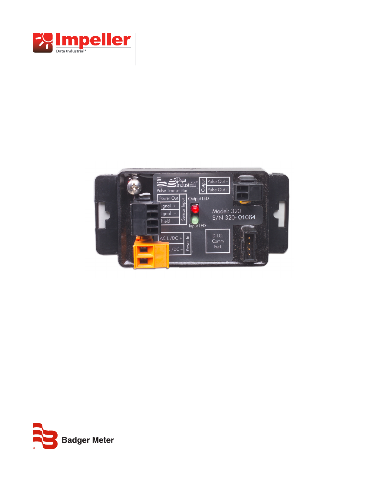
Description
DESCRIPTION
Model 320 from Badger Meter is a compact, programmable transmitter designed to accept relatively fast unscaled raw pulses
from devices like flow sensors, and then output slow-scaled pulses of programmable width, pulse resolution and units of
measure. In addition to our standard flow sensors, the Model 320 can also accept a sine wave signal, making it a versatile
transmitter for numerous applications.
SCOPE AND PURPOSE
This manual provides instructions for installing and programming the Model 320 transmitter.
MECHANICAL INSTALLATION
The Model 320 can be surface mounted onto a panel, attached to DIN rails using adapter clips or wall mounted using two
optional enclosures.
Location
Although the Model 320 is encapsulated, all wiring connections are made to exposed terminals. The unit should be protected
from weather and moisture in accordance with electrical codes and standard trade practices. In any mounting arrangement,
the primary concerns are ease of wiring and attachment of the programming cable. The unit generates very little heat so no
consideration need be given to cooling or ventilation.
Surface Mount Installation
The Model 320 can be mounted to the surface of any panel using double sided adhesive tape, or by attaching fasteners
through the holes in the mounting flanges of the unit.
DIN Rail Mounting
Optional clips snap onto the mounting flanges, allowing the Model 320 to be attached to DIN 15, 32, 35 mm DIN rail systems.
Wall Mounting
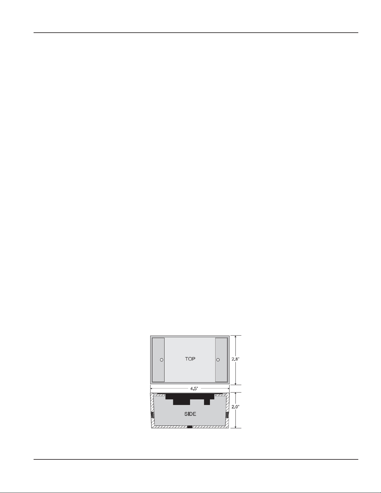
Optional metal and plastic enclosures are available to mount the Model 320 to a wall when no other enclosure is used. The
enclosure is first attached to the wall using fasteners through its mounting holes. After wiring, the transmitter can be attached
to the enclosure with the terminal headers facing in, using the slots in the mounting flanges. As an alternate mounting
arrangement, the Model 320 can be fastened to the box cover using double-sided adhesive tape.
Figure 1: Optional enclosure dimensions
Page 3 July 2015 XMT-UM-01654-EN-07
Page 4

Electrical Installation
ELECTRICAL INSTALLATION
According to standard wiring practices, the power must be off before making any wire connections. The terminal strips have
removable plug-in connectors to make wiring easier.
OTE:N Refer to Figure 2 and Figure 3 for terminal connections and wiring example.
1. Connect DC power supply positive (+) or AC Line to the terminal marked AC L /DC (+).
2. Connect DC power supply negative (–) or AC Common to the terminal marked AC C /DC (–).
Figure 2: Terminal locations
3. If wiring to a 200 sensor, connect the red wire to the Signal (+) terminal, black wire to the Signal (–) terminal and the shield
to the Shield terminal. (Disregard shield for the IR sensors.)
If wiring to a 4000 sensor, connect the red wire to the Power Out terminal, clear wire to the Signal (+) terminal, black wire
to the Signal (–) terminal and shield wire to the Shield terminal.
If wiring to a sine wave output sensor, consult the factory.
4. Connect Pulse(+) from pulse input device to Pulse Out(+) of the 320, connect Pulse (–) from pulse input device to Pulse
Out (–) of the 320.
5. For maximum EMI protection, connect the Model 320 ground lug to the panel ground.
6. Make sure all connections are tight. Then plug the connector into the header.
Figure 3: Wiring to a generic pulse device and Model 200 or 4000
OTE:N Included with every Model 320 is a 320 IK installation kit containing a screw, lock washer and ground lead to
connect the Model 320 to Earth Ground. This will help prevent electrical interference from affecting the Model 320
normal operation.
Page 4 July 2015XMT-UM-01654-EN-07
Page 5

Programming
Communications Cable Wiring
Field calibration requires an A320 programming kit (consisting
of a custom cable and software) and a computer (PC) running
Windows® 7, XP or Vista. To program, the Model 320 must be
connected to power, and the A301 cable must be connected to
the Model 320 Comm port connector and an available DB9 port
on the PC.
Figure 4: Location of the DIC communication port
OTE:N The Data Industrial A301 cable will work with all 300 Model products. However, the older version of the cable (A300)
does not have sufficient bandwidth to work with the newer 340 Model Transmitters or SDI Flow Sensors.
PROGRAMMING
Disk Installation
Load the software CD into the CD ROM drive of the computer and it should autostart. Select the software to start the
installation.
Web Installation
Free programming software updates are available via the Badger Meter website at www.badgermeter.com.
Model 320 Programming
To program the Model 320, install the programming software on a computer (PC) and enter data on templates in the
Windows® based program.
1. Load the software on the PC.
2. Connect the PC to the Model 320 transmitter using the
A301 communications cable.
• Plug the A301 cable into the socket labeled “D.I.C
Comm Port,” taking care to properly align the tab on
the plug and socket to maintain polarity.
• Then plug the DB9 connector of the A301
communications cable into an available port on the
same PC that has the software installed.
3. Connect the Model 320 transmitter to a power supply.
4. Open the software and select the appropriate COM PORT using the drop-down menu. See Figure 5.
5. Select Parameters as shown in Figure 6 to open the Parameters screen.
Figure 5: Select the COM port
Figure 6: Select Parameters
6. Program using the diagram in Figure 7 as a reference.
Page 5 July 2015 XMT-UM-01654-EN-07
Page 6

Programming
Figure 7: Program using the diagram as reference
OTE:N
• If the SDI sensor type is selected, the required K and Offset values can be found in the SDI owners manual.
• If the 4000 sensor type is selected, click the drop-down menu and select the sensor from the list that displays.
• Sine is provided for connection to sensors with a sine wave output. Consult the sensor manufacturer for the calibration
settings.
• If the 200 Insert sensor type is selected, the required K and Offset can be found in the 200 owner's manual, or press the
calculate button, enter an inside pipe diameter and press calculate to automatically enter the K and Offset values.
• If the 200 tee type is selected, click the drop-down menu and select the sensor from the list that displays.
Page 6 July 2015XMT-UM-01654-EN-07
Page 7

SPECIFICATIONS
Power 12…28V AC RMS, 85mA max
12…40V DC, 30mA max
Reverse and over voltage protected
Input Frequency 0.4…10 kHz
Transient Suppression Complies with IEC-801-4 electrical burst, fast transient specification
Pulse Output Isolated solid state switch in any standard or custom flow
Total units adjustable 50 mS to 1.0 second pulse output width in 50 mS increments
Maximum sinking current: 100 mA at 36V DC
Temperature Operating: –29…70C (–20…158F )
Storage: –40…85C (–40…185F
Specications
Page 7 July 2015 XMT-UM-01654-EN-07
Page 8

Transmitters, Model 320 Programmable Pulse
Control. Manage. Optimize.
Trademarks appearing in this document are the property of their respective entities. Due to continuous research, product improvements and enhancements, Badger Meter reserves
the right to change product or system specications without notice, except to the extent an outstanding contractual obligation exists. © 2015 Badger Meter, Inc. All rights reserved.
www.badgermeter.com
The Americas | Badger Meter | 4545 West Brown Deer Rd | PO Box 245036 | Milwaukee, WI 53224-9536 | 800-876-3837 | 414-355-0400
México | Badger Meter de las Americas, S.A. de C.V. | Pedro Luis Ogazón N°32 | Esq. Angelina N°24 | Colonia Guadalupe Inn | CP 01050 | México, DF | México | +52-55-5662-0882
Europe, Middle East and Africa | Badger Meter Europa GmbH | Nurtinger Str 76 | 72639 Neuen | Germany | +49-7025-9208-0
Europe, Middle East Branch Oce | Badger Meter Europe | PO Box 341442 | Dubai Silicon Oasis, Head Quarter Building, Wing C, Oce #C209 | Dubai / UAE | +971-4-371 2503
Czech Republic | Badger Meter Czech Republic s.r.o. | Maříkova 2082/26 | 621 00 Brno, Czech Republic | +420-5-41420411
Slovakia | Badger Meter Slovakia s.r.o. | Racianska 109/B | 831 02 Bratislava, Slovakia | +421-2-44 63 83 01
Asia Pacic | Badger Meter | 80 Marine Parade Rd | 21-06 Parkway Parade | Singapore 449269 | +65-63464836
China | Badger Meter | 7-1202 | 99 Hangzhong Road | Minhang District | Shanghai | China 201101 | +86-21-5763 5412 Legacy Document: 872024
 Loading...