

Page 1

Transmitters
Model 310 Programmable Analog
XMT-UM-01653-EN-07 (July 2015)
User Manual
Page 2

Transmitters, Model 310 Programmable Analog
CONTENTS
Description . . . . . . . . . . . . . . . . . . . . . . . . . . . . . . . . . . . . . . . . . . . . . . . . . . . . . . . . . . . . . . . . . . . . . . . . . 3
Scope and Purpose . . . . . . . . . . . . . . . . . . . . . . . . . . . . . . . . . . . . . . . . . . . . . . . . . . . . . . . . . . . . . . . . . . . . 3
Mechanical Installation. . . . . . . . . . . . . . . . . . . . . . . . . . . . . . . . . . . . . . . . . . . . . . . . . . . . . . . . . . . . . . . . . . 3
Location . . . . . . . . . . . . . . . . . . . . . . . . . . . . . . . . . . . . . . . . . . . . . . . . . . . . . . . . . . . . . . . . . . . . . . . . 3
Surface Mount Installation. . . . . . . . . . . . . . . . . . . . . . . . . . . . . . . . . . . . . . . . . . . . . . . . . . . . . . . . . . . . . 3
DIN Rail Mounting . . . . . . . . . . . . . . . . . . . . . . . . . . . . . . . . . . . . . . . . . . . . . . . . . . . . . . . . . . . . . . . . . . 3
Wall Mounting . . . . . . . . . . . . . . . . . . . . . . . . . . . . . . . . . . . . . . . . . . . . . . . . . . . . . . . . . . . . . . . . . . . . 4
Electrical Installation . . . . . . . . . . . . . . . . . . . . . . . . . . . . . . . . . . . . . . . . . . . . . . . . . . . . . . . . . . . . . . . . . . . 5
Communications Cable Wiring . . . . . . . . . . . . . . . . . . . . . . . . . . . . . . . . . . . . . . . . . . . . . . . . . . . . . . . . . . 6
Software Installation . . . . . . . . . . . . . . . . . . . . . . . . . . . . . . . . . . . . . . . . . . . . . . . . . . . . . . . . . . . . . . . . . . . 6
CD Installation . . . . . . . . . . . . . . . . . . . . . . . . . . . . . . . . . . . . . . . . . . . . . . . . . . . . . . . . . . . . . . . . . . . . 6
Web Installation . . . . . . . . . . . . . . . . . . . . . . . . . . . . . . . . . . . . . . . . . . . . . . . . . . . . . . . . . . . . . . . . . . . 6
Programming. . . . . . . . . . . . . . . . . . . . . . . . . . . . . . . . . . . . . . . . . . . . . . . . . . . . . . . . . . . . . . . . . . . . . . . . 7
Connecting Via D.I.C. Comm Port. . . . . . . . . . . . . . . . . . . . . . . . . . . . . . . . . . . . . . . . . . . . . . . . . . . . . . . . . 7
Programming Parameters . . . . . . . . . . . . . . . . . . . . . . . . . . . . . . . . . . . . . . . . . . . . . . . . . . . . . . . . . . . . . 9
Specications . . . . . . . . . . . . . . . . . . . . . . . . . . . . . . . . . . . . . . . . . . . . . . . . . . . . . . . . . . . . . . . . . . . . . . . 11
Page ii July 2015XMT-UM-01653-EN-07
Page 3
Description
DESCRIPTION
Model 310 from Badger Meter is a loop-powered, programmable 4-20mA transmitter designed to accept relatively fast,
unscaled raw pulses from devices like flow sensors, and then transmit a linear analog signal of desired scaling and units of
measure. In addition to our standard flow sensors, the Model 310 can also accept a sine wave, making it a versatile transmitter
for numerous applications.
SCOPE AND PURPOSE
This manual provides instructions for installing and programming the Model 310 transmitter.
MECHANICAL INSTALLATION
The Model 310 can be surface mounted onto a panel, attached to DIN rails using adapter clips or wall mounted using two
optional enclosures.
Location
Although the Model 310 is encapsulated, all wiring connections are made to exposed terminals. The unit should be protected
from weather and moisture in accordance with electrical codes and standard trade practices.
In any mounting arrangement, the primary concerns are ease of wiring and attachment of the programming cable. The unit
generates very little heat so no consideration need be given to cooling or ventilation.
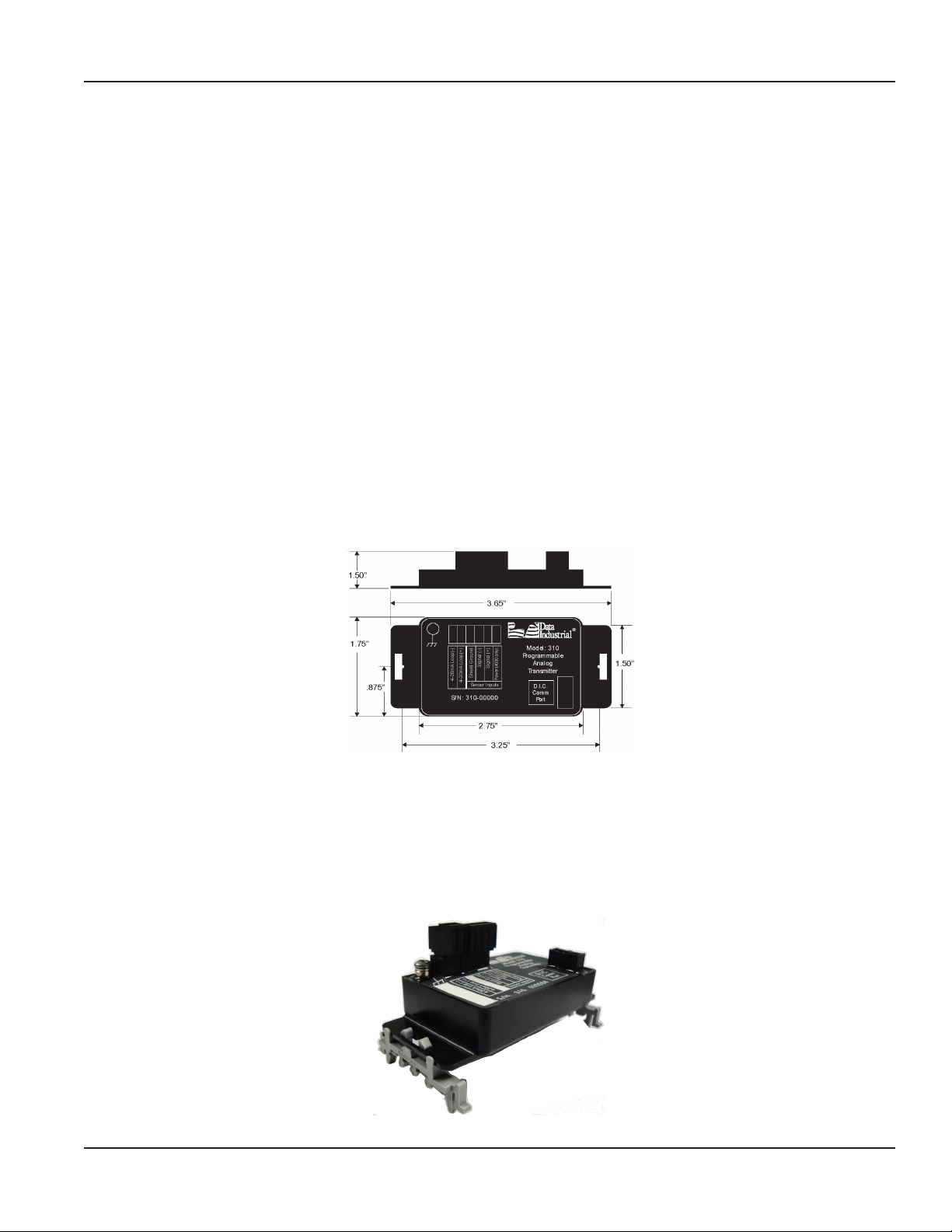
Figure 1: Model 310 transmitter board dimensions
Surface Mount Installation
The Model 310 can be mounted to the surface of any panel using double-sided adhesive tape or by attaching fasteners
through the holes in the mounting flanges of the unit.
DIN Rail Mounting
Optional clips snap onto the mounting flanges allowing the Model 310 to be attached to DIN 15, 32, 35 mm DIN rail systems.
Figure 2: DIN rail mounting
Page 3 July 2015 XMT-UM-01653-EN-07
Page 4
Mechanical Installation
Wall Mounting
For locations requiring additional protection, three wall mount options are available.
310-01 NEMA 4x Plastic Enclosure
The 310-01 NEMA 4x plastic enclosure is usually used in
industrial or commercial locations requiring this rating. This
version is shipped with the Model 310 secured to the cover
with double-sided adhesive tape.
Length = 4.72" (120 mm) Width = 3.15" (80 mm) Height =
2.17" (55 mm)
The enclosure is secured to the wall by screws inserted
through the rear corners, outside the o-ring seal area.
Watertight conduit connectors must be used if the NEMA 4x
rating is to be maintained.
310-02 Metal Enclosure
The 310-02 metal enclosure is weather tight and made for
installations needing additional impact protection. It is
shipped with the Model 310 mounted in an inverted position
secured by the cover screws.
Double-sided adhesive tape is included should the installer
prefer this method to secure the cover. The box is secured to
the wall with a screw through the rear, or can be supported
by conduit
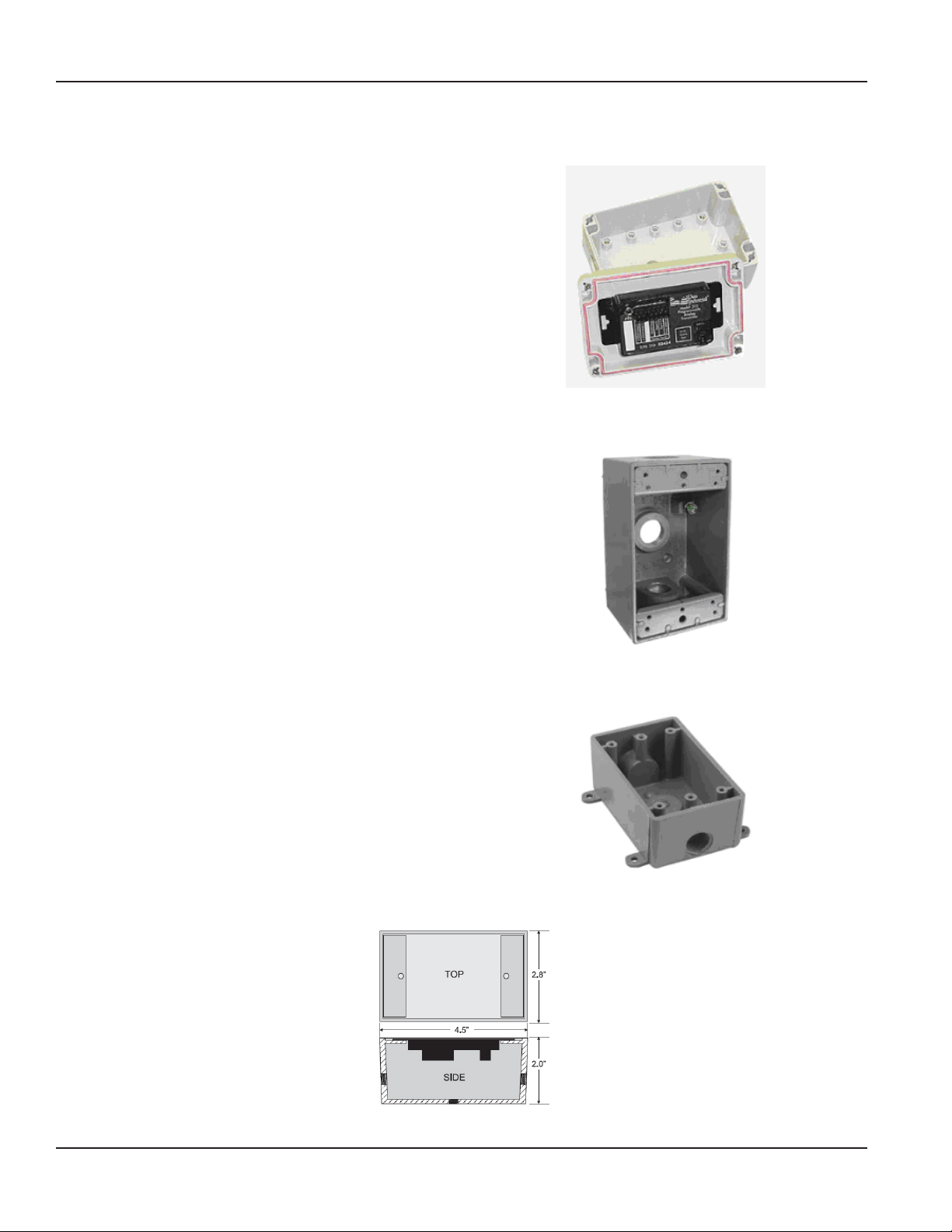
Figure 3: 310-01 NEMA 4x plastic enclosure
310-03 Plastic Enclosure
The 310-03 plastic enclosure is weather tight and good for
outdoor locations. It is shipped with the Model 310 secured
to the cover with double-sided adhesive tape.
Length = 4.50" (114.3 mm) Width = 2.8" (71.12 mm) Height =
2.0" (50.8 mm)
The enclosure is secured to the wall by screws inserted
through side tabs as shown in Figure 5.
Figure 4: 310-02 metal enclosure
Figure 5: 310-03 plastic enclosure
Figure 6: Optional enclosure dimensions (310-02 and 310-03)
Page 4 July 2015XMT-UM-01653-EN-07
Page 5

®
Sensor Inputs
Industrial
4-20mA Loop(+)
Shield Groun d
Power (40 00 only)
Model: 310
Programmable
Anal og
Transmitter
D.I. C.
Comm
Po r t
Signal (-)
Signal (+)
®
Mattapoisett, MA 02739
Sensor
Input
DIC
Communications Port
Side View - Typical 300 Series
Removable Connector Wiring
Electrical Installation
ELECTRICAL INSTALLATION
According to standard wiring practices, loop power must be off before making any wire connections.
The Model 310 is a non-isolated, loop-powered transmitter. The sensor connections must be electrically floating – with no
path to loop power. Any path from the sensor to the loop power supply would result in ground faults that would affect
calibration and potentially damage the Model 310 or any devices connected. For this reason the Model 310 cannot share a
sensor signal with another device and cannot be used with intrinsic safety barriers without the use of an optic isolator.
The terminal strips have removable plug-in connectors to make wiring easier.
Wire
Series 300
3/32” Flathead
Screwdriver
Connector
Figure 7: Side View – Typical 300 series removable connector wiring
The Model 310 is shipped with a two-pin Analog Output connector, and a four-pin Sensor Input connector. The programming
kit is required to configure the Model 310 and is sold separately. The kit includes a programming cable with a DB9 connector
on one end and a connector that plugs into the Model 310 port labeled D.I.C. Comm Port on the other (Figure 8). If a
computer serial port is not available, a USB to COM port adapter can be purchased locally.
A310-20 programming cable
(purchased separately)
Two Pin – Analog output connector
(Part # 855815)
Four Pin – Sensor input connector
(Part # 855814)
Figure 8: Model 310 connectors
Page 5 July 2015 XMT-UM-01653-EN-07
Page 6

Figure 4: Model 310 Wiring to Analog Loop and Series 200 or Series 4000
Figure 3: Model 310 Terminal Locations
S/N: 310- 00000
®
Sensor Inputs
Industrial
4-20mA Loop(-)
4-20mA Loop(+)
Shield Ground
Power (4000 only)
Model: 310
Programmable
Analo g
Transmitter
D.I.C .
Comm
Po rt
Signal (-)
Signal (+)
®
Mattapoisett, MA 02739
Ground
Lug
A
nalog
Output
Sensor
Input
DIC
Communications Port
Shield (if applicable)
Series 200
Side View - Typical 300 Series
Removable Connector Wiring
3/32” Flathead
Screwdriver
Series 300
Connector
Wire
Software Installation
1. As shown in Figure 9, connect the loop power supply positive (+) to the Model 310 terminal marked 4-20mA loop (+).
24Vdc
Power
Supply
-
-
Analog
Input
Device
Black
Red
Shield
Industrial
Black
White(Clear)
Red
®
®
+
4-20mA Loop(+)
Signal (-)
Shield Ground
Sensor Inputs
Signal (+)
Power (40 00 only)
Mattapoisett, M A 02739
Model: 310
Programmable
Analo g
Transmitter
D.I.C .
Comm
Po rt
+
4-20mA Loop(-)
S/N: 310-00000
Data
Industrial
4000 Series
FLOW
Series 4000
Sensor
Sensor
Figure 9: Model 310 wiring to Analog loop and Series 200 or 4000
2. Connect the Model 310 terminal marked 4-20mA loop (–) to the positive (+) analog terminal of the input device (Chart
Recorder, PLC, etc.).
3. Connect the negative (–) analog terminal of the input device to the negative (–) terminal of the loop power supply.
4. If wiring a 200 sensor, connect the red wire (signal) to the Signal (+) terminal, black wire (common) to the Signal (–)
terminal and the shield to the Shield Ground terminal (disregard shield for the IR sensors).
If wiring a 4000 sensor, connect the clear wire (signal) to the Signal (+) terminal, black wire (common) to the Signal (– )
terminal, shield wire to the Shield Ground terminal and red wire (power) to the Power (4000 only) terminal.
If wiring to a sine wave output sensor, consult the factory.
5. For maximum EMI protection, connect the Model 310 ground lug to panel ground.
OTE:N Included with every Model 310 is a 310-IK (installation kit) containing a screw, a lock washer and a ground lead
to connect the Model 310 to earth ground. This will help prevent electrical shock interference from affecting the
normal operation of the 310.
6. Make sure all connections are tight. Then plug the connector into the header.
Communications Cable Wiring
Field configuration requires a Badger Meter programming kit (consisting of a custom cable and software, sold separately) and
a computer (PC) running Windows® 7, XP or Vista. To connect, the Model 310 must be powered with a minimum of 9V DC
across the +/– loop terminals and have at least 4mA of current flowing.
The A301 cable must be connected to the Model 310 "Comm" port connector and an available 9-pin serial port on the PC. A
USB to COM port adapter can be used if the DB9 port is not available.
OTE:N Badger Meter provides free programming software updates via the Internet for all 300 devices. Go to
www.badgermeter.com. Software updates can be found at Flow Instrumentation/Impeller Products/Transmitters.
SOFTWARE INSTALLATION
CD Installation
Place the software disk from the programming kit (sold separately) in the computer drive and follow the on
screen instructions.
Web Installation
Go to Flow Instrumentation/Impeller Products/Transmitters at www.badgermeter.com to access the installation software:
Page 6 July 2015XMT-UM-01653-EN-07
Page 7

Programming
PROGRAMMING
Connecting Via D.I.C. Comm Port
Programming the Model 310 is accomplished by installing the programming software on a computer (PC) and entering data
on templates of the Windows-based program.
The Model 310 is normally shipped from the factory with the default setting of K=1.0, Offset = 0.0, 4 mA = 0, and
20 mA = 10,000. These settings were chosen to allow the 310 to operate but in such a way that the output cannot be confused
with actual operational settings. As a result, the 4-20 mA output will be 4 mA with no flow input signal, and less than 6mA
even with a high flow input signal. The 310 must be configured in the field before it will transmit a useful signal.
1. Load the software on the PC.
2. Connect the Model 310 to a powered 4-20 mA loop. If setting up in the oce, a 9-24V DC power source can be used to
simulate the loop.
OTE:N The 310 will not communicate if there is not at least a minimum of 4 mA, 9V DC across the loop+ and
loop terminals.
3. Connect the computer to the Model 310 transmitter socket labeled "D.I.C. Comm Port" using the A-301 communications
cable, taking care to properly align the tab on the plug and socket to maintain polarity.
4. Connect the DB9 connector of the A301 communications cable to a port on the PC that has the software installed. If a DB9
port is not available on the PC, a USB to COM port adapter can be purchased locally.
5. Open the program and from the Device option in the menu bar, select 310 as shown in Figure 10.
Figure 10: Select 310
6. From the Conguration option in the menu bar, select Set Comm Port. The Comm Settings window opens (Figure 12).
Figure 11: Set Comm Port
Figure 12: Select "Comm" port
Page 7 July 2015 XMT-UM-01653-EN-07
Page 8

Programming
7. Select the "Comm" port and then click OK. If the Comm port and Device type have been properly selected, the dashes "---"
on the screen will be replaced with values. See Figure 14.
If this does not occur, communication has not been
established and you cannot continue to the next step. To
establish communication, click the Poll Now button.
If communication still does not occur and you are using
a DB9 to Comm 1 or Comm 2, use a USB to COM adapter.
The USB to COM adapter will create a new port that
was not previously listed. The Ports (COM & LPT) file in
Windows Device Manager can be helpful in determining
the actual ports that are available.
To access Device Manager, click the Start/Windows icon
in the lower left corner on the main task bar of the PC.
Then go to Control Panel > Device Manager and click
the small arrow next to Ports (COM & LPT) to expand the
file. See the example in Figure 13.
Figure 13: Ports (COM & LPT) in Device Manager
Select the new port created by the adapter. The screen
should show the dashes "---" replaced with values, which
confirms communications are properly established as in
Figure 14.
8. When communication has been conrmed, click the
Parameters button to display the Parameters screen. See
the example in Figure 15.
Figure 15: Parameters screen
Figure 14: Communications established - value filled
Page 8 July 2015XMT-UM-01653-EN-07
Page 9
Programming Parameters
1. From the Parameters screen, program the following:
• Flow Sensor Configuration and Flow Rate Units
• Filter Coefficient (flow and energy averaging for reading stability)
• Analog Loop Settings
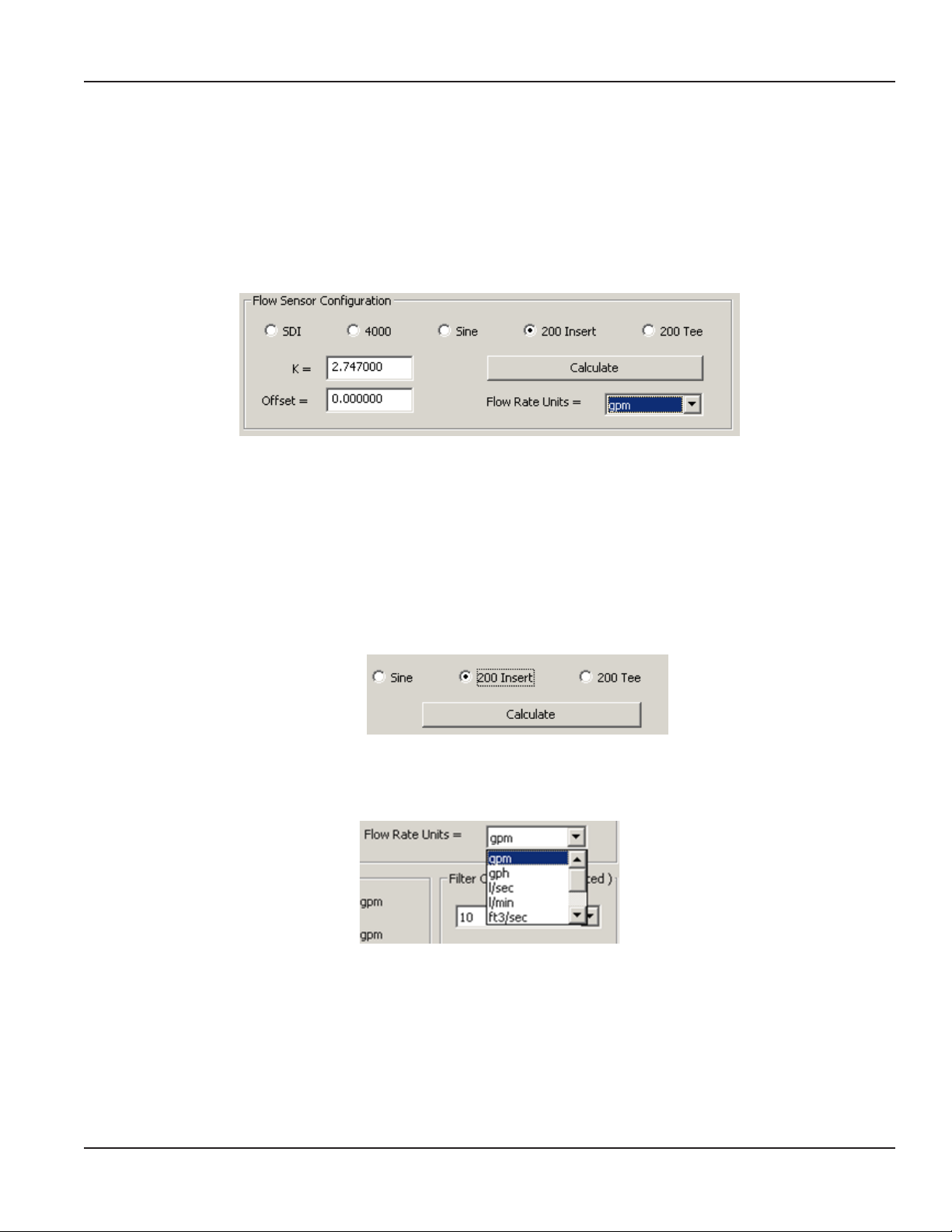
2. Select the Sensor type and enter the K and Oset values.
Figure 16: Flow sensor configuration
• SDI: If the SDI sensor is selected, the required K and Offset values can be found in the SDI owner's manual.
• 4000: If the 4000 sensor is selected, select the sensor from the drop-down menu that appears.
Programming
• Sine: Provided for connection to sensors which have a sine wave output. Consult the sensor manufacturer for
the calibration settings.
• 200: If the 200 Insert is selected, the Calculate button appears. Enter the required K and Offset values found in
the 200 owners manual. Or click the Calculate button and enter an inside pipe diameter and the K and Offset
values will automatically be entered in.
Figure 17: Calculate button for 200 Insert sensor
• 200 Tee: If the 200 Tee sensor is selected, select the sensor from the drop-down menu that appears.
3. Select Flow Rate Units from the drop-down menu.
Figure 18: Flow Rate Units menu
Page 9 July 2015 XMT-UM-01653-EN-07
Page 10

Programming
4. Enter the Analog Loop Settings: 4 mA rate and 20 mA rate.
The 4-20 mA output is a linear representation of ow rate. Except under very unusual circumstances, 4 mA is set to
represent 0.00 ow.
Figure 19: Analog loop settings
20 mA should be selected to represent a flow greater than ever expected to occur. This will prevent the analog output
from running out of range and locking on 20 mA at times of high flow. However, 20 mA should not be set at such a high
value that even at times of high flow the output does not exceed 60-80% of full scale. Doing so will waste the range of the
meter and affect the system's signal-to-noise ratio. It is also very important that the range of the device receiving the 4-20
mA as an input be scaled in exactly the same way as the Model 310.
5. The Filter Coecients are a weighted, moving average used to smooth out any instability in the incoming ow
signal. The instability is usually the result of a disturbed ow prole due to inadequate straight pipe, ttings or other
variables. Set the value from 0…20, with 3 as the factory default. For most applications leave the default setting of 3 if the
ow rate or energy rates are, for some reason, unstable (from a disturbed ow prole, for example). Increase the values
as needed.
6. To save any changes, click Send before leaving the screen.
Figure 20: Click Send to save changes
Other options are:
Refresh – rereads the unit and refreshes the screen with the current 310 settings.
Defaults – restores all factory settings.
Exit – returns to the Main screen.
Page 10 July 2015XMT-UM-01653-EN-07
Page 11

SPECIFICATIONS
Power Requirements Loop input voltage 9…35V DC
Input Frequency 0.4…10 kHz
Load Resistance Max 750 Ω @ 24V DC
Output Response Time Varies with filter
Temperature (operating) –29…70oC
–20…158oF
Temperature (storage) –40…85oC
–40…185oF
Accuracy ±0.04% of reading over entire span
Linearity 0.1% of full scale
Specications
Page 11 July 2015 XMT-UM-01653-EN-07
Page 12

Transmitters, Model 310 Programmable Analog
Control. Manage. Optimize.
Trademarks appearing in this document are the property of their respective entities. Due to continuous research, product improvements and enhancements, Badger Meter reserves
the right to change product or system specications without notice, except to the extent an outstanding contractual obligation exists. © 2015 Badger Meter, Inc. All rights reserved.
www.badgermeter.com
The Americas | Badger Meter | 4545 West Brown Deer Rd | PO Box 245036 | Milwaukee, WI 53224-9536 | 800-876-3837 | 414-355-0400
México | Badger Meter de las Americas, S.A. de C.V. | Pedro Luis Ogazón N°32 | Esq. Angelina N°24 | Colonia Guadalupe Inn | CP 01050 | México, DF | México | +52-55-5662-0882
Europe, Middle East and Africa | Badger Meter Europa GmbH | Nurtinger Str 76 | 72639 Neuen | Germany | +49-7025-9208-0
Europe, Middle East Branch Oce | Badger Meter Europe | PO Box 341442 | Dubai Silicon Oasis, Head Quarter Building, Wing C, Oce #C209 | Dubai / UAE | +971-4-371 2503
Czech Republic | Badger Meter Czech Republic s.r.o. | Maříkova 2082/26 | 621 00 Brno, Czech Republic | +420-5-41420411
Slovakia | Badger Meter Slovakia s.r.o. | Racianska 109/B | 831 02 Bratislava, Slovakia | +421-2-44 63 83 01
Asia Pacic | Badger Meter | 80 Marine Parade Rd | 21-06 Parkway Parade | Singapore 449269 | +65-63464836
China | Badger Meter | 7-1202 | 99 Hangzhong Road | Minhang District | Shanghai | China 201101 | +86-21-5763 5412 Legacy Document: 872019
 Loading...