

Page 1
Transmitters
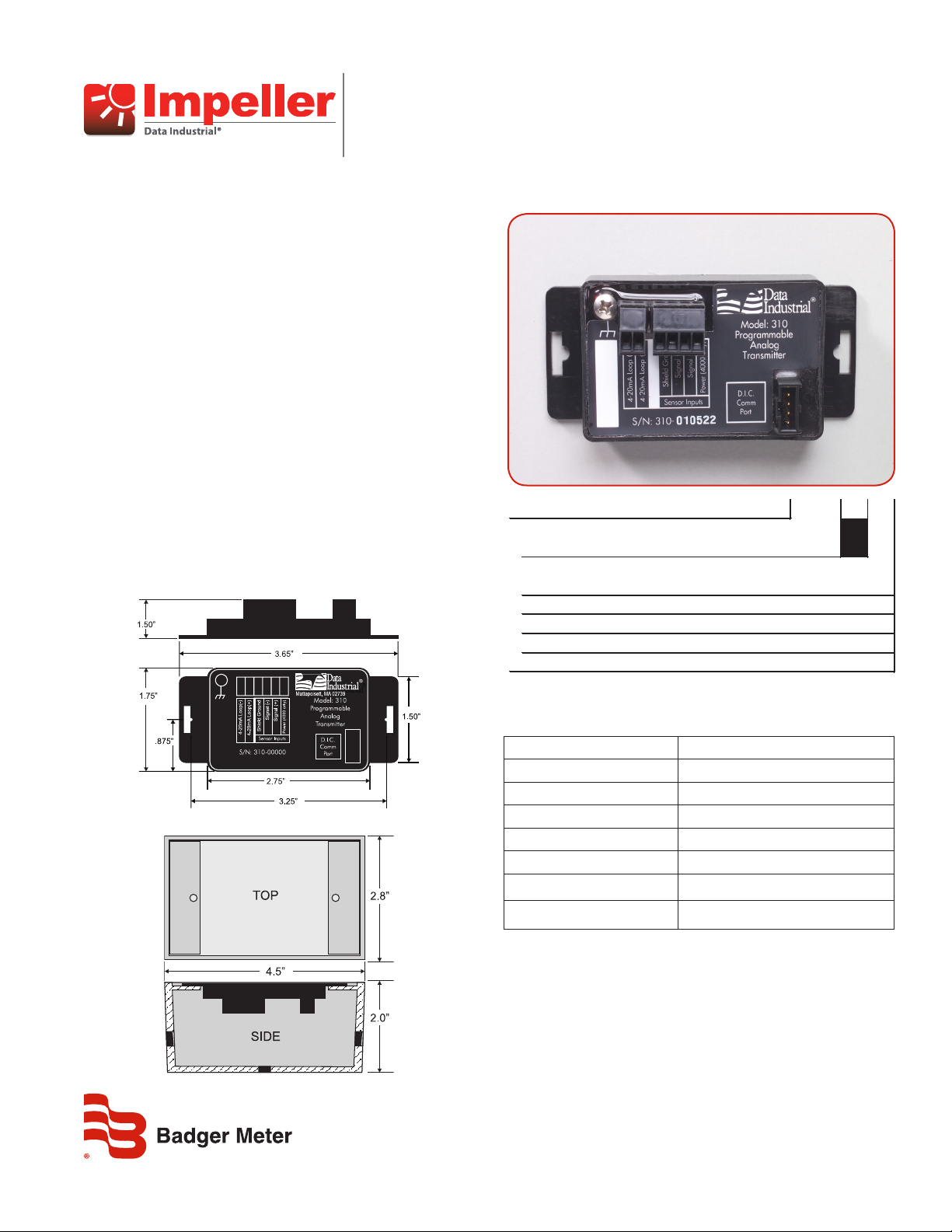
EXAMPLE: 310-xx
SERIES
Programmable Analog Transmitter 310
OPTIONS
Transmitter Only 00
W / NEMA 4X Enclosure01
W / Metal Weathertite Enclosure02
W / Plastic Weathertite Enclosure03
W / DIN rail Mounting Clips04
Model 310 Programmable Analog
OVERVIEW
The Model 310 from Badger Meter is a loop-powered,
programmable 4-20mA transmitter designed to accept relatively
fast, unscaled raw pulses from devices like flow sensors and then
transmit a linear analog signal of desired scaling and units of
measure. In addition to our standard flow sensors, the Model 310
can also accept a sine wave, making it a versatile transmitter for
numerous applications.
With an onboard microcontroller and digital circuitry, the Model
310 is programmed from a computer, thereby eliminating the need
to adjust potentiometers and produce precise, accurate and
drift-free signals. This saves both time and money by lowering
overall maintenance times. This model also has an integral filter
that the user can specify as values between 0 (to show true sensor
readings) and 10 (for maximum dampening).
The compact cast epoxy body measures 1.75 x 2.75 x 1 inches
(44 x 70 x 25 mm) and can easily be mounted to panels, DIN rails or
enclosures. With field programming, input signal flexibility,
ease of use and a variety of enclosures, the Model 310 is a
powerful and competitive transmitter for many of today’s
demanding applications.
Figure 1: Dimensions
XMT-DS-01629-EN-02 (July 2015)
Figure 2: Optional enclosure (Ver. 310-02 and 310-03)
Figure 3: Model 310 ordering matrix
SPECIFICATIONS
Power Requirements Loop input voltage 9…35V DC
Input Frequency 0.4…10 kHz
Load Resistance Max 750 Ω at 24V DC
Output Response Time Varies with lter
Temperature (Operating) –29…70C; –20…158F
Temperature (Storage) –40…85C; –40…185F
Accuracy ±0.04% of reading over entire span
Linearity 0.1% of full scale
CALIBRATION
Units can be calibrated at our facility or easily programmed in
the field. Field calibration requires an A301-20 programming kit
(consisting of a custom cable and software) and a computer (PC)
running a Windows® 7, XP or Vista operating system. To calibrate,
the Model 310 must be connected to the loop for power and the
A301-20 programming kit cable must be connected to an available
9-pin port on the computer. If the computer does not have a DB-9
port, a USB-to-COM port adapter can be used.
Product Data Sheet
Page 2
Transmitters, Model 310 Programmable Analog
Calibration, continued
Once the software is loaded and transmitter communication is established, the following parameters are entered on the setup screens:
• Units of measure
• K and Offset values – selected from the sensor owners manual or for insert style sensors entering the pipe ID allows the software to
calculate the K and Offset values
• Flow rate represented by 4mA
• Flow rate represented by 20mA
An added feature is a user selectable filter. Set at the minimum (0), the transmitter reacts to actual flow input. Set at the maximum (10), the
transmitter provides the greatest dampening possible. Once the values are set, the “send” command loads the transmitter.
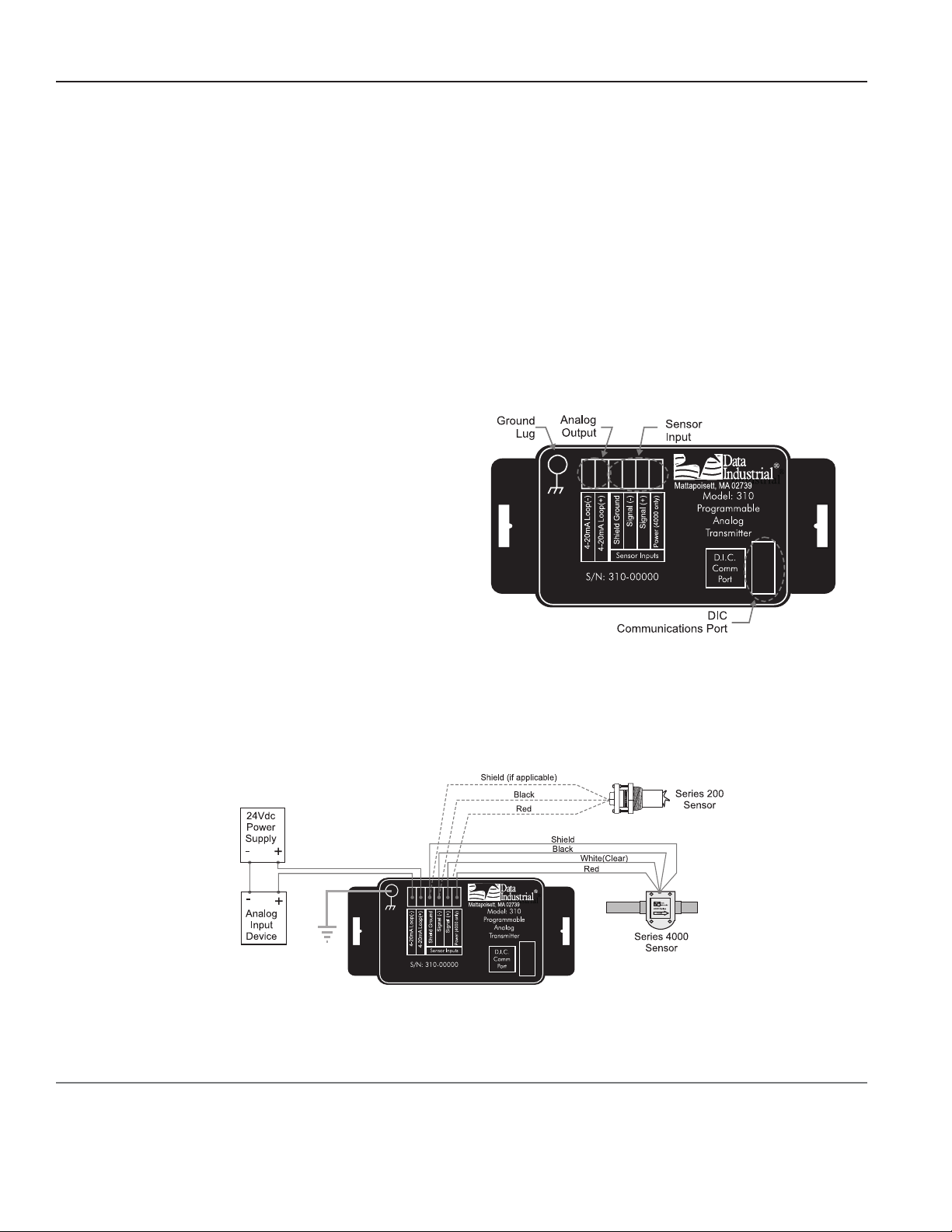
WIRING
Per standard wiring practices, the loop power must be off before making any wire connections. The terminal strips have removable plug-in
connectors to make wiring easier. Refer to Figure 4 for terminal connections.
1. Connect loop power supply positive (+) to the terminal marked
4-20mA loop (+).
2. Connect the terminal marked 4-20mA loop (–) of the Model
310 to the positive analog terminal of the input device (Chart
Recorder, PLC, etc.).
3. Connect negative analog terminal of the input device to loop
power supply negative.
4. If wiring a 200 sensor, connect the red wire (signal) to the Signal
(+) terminal, black wire (ground) to the Signal (–) terminal, and
the shield to the Shield Ground terminal (disregard shield for the
IR sensors).
If wiring a 4000 sensor, connect the clear wire (signal) to the
Figure 4: Terminal connections
Signal (+) terminal, black wire (ground) to the Signal (–) terminal, shield wire to the Shield Ground terminal, and red wire (power) to the
Power (4000 only) terminal.
If the sensor is not a Badger Meter Data Industrial 200, go to step 6.
5. For maximum EMI protection, connect the Model 310 ground lug to the panel ground.
6. Make sure all connections are tight. Then plug the connector into the header.
Control. Manage. Optimize.
Data Industrial is a registered trademark of Badger Meter, Inc. Other trademarks appearing in this document are the property of their respective entities. Due to continuous
research, product improvements and enhancements, Badger Meter reserves the right to change product or system specications without notice, except to the extent an
outstanding contractual obligation exists. © 2015 Badger Meter, Inc. All rights reserved.
Figure 5: Typical wiring example
www.badgermeter.com
The Americas | Badger Meter | 4545 West Brown Deer Rd | PO Box 245036 | Milwaukee, WI 53224-9536 | 800-876-3837 | 414-355-0400
México | Badger Meter de las Americas, S.A. de C.V. | Pedro Luis Ogazón N°32 | Esq. Angelina N°24 | Colonia Guadalupe Inn | CP 01050 | México, DF | México | +52-55-5662-0882
Europe, Middle East and Africa | Badger Meter Europa GmbH | Nurtinger Str 76 | 72639 Neuen | Germany | +49-7025-9208-0
Europe, Middle East Branch Oce | Badger Meter Europe | PO Box 341442 | Dubai Silicon Oasis, Head Quarter Building, Wing C, Oce #C209 | Dubai / UAE | +971-4-371 2503
Czech Republic | Badger Meter Czech Republic s.r.o. | Maříkova 2082/26 | 621 00 Brno, Czech Republic | +420-5-41420411
Slovakia | Badger Meter Slovakia s.r.o. | Racianska 109/B | 831 02 Bratislava, Slovakia | +421-2-44 63 83 01
Asia Pacic | Badger Meter | 80 Marine Parade Rd | 21-06 Parkway Parade | Singapore 449269 | +65-63464836
China | Badger Meter | 7-1202 | 99 Hangzhong Road | Minhang District | Shanghai | China 201101 | +86-21-5763 5412
Legacy Document Number: DTB-013-03
 Loading...