

Page 1
Industrial Flow Monitors
Series 3050
DSY-UM-01668-EN-02 (June 2018)
User Manual
Page 2

Industrial Flow Monitors, Series 3050
Page ii June 2018DSY-UM-01668-EN-02
Page 3

User Manual
CONTENTS
Introduction. . . . . . . . . . . . . . . . . . . . . . . . . . . . . . . . . . . . . . . . . . . . . . . . . . . . . . . . . . . . . . . . . . . . . . . . . .5
Programming . . . . . . . . . . . . . . . . . . . . . . . . . . . . . . . . . . . . . . . . . . . . . . . . . . . . . . . . . . . . . . . . . . . . . . 5
Options . . . . . . . . . . . . . . . . . . . . . . . . . . . . . . . . . . . . . . . . . . . . . . . . . . . . . . . . . . . . . . . . . . . . . . . . . .5
Safety Information. . . . . . . . . . . . . . . . . . . . . . . . . . . . . . . . . . . . . . . . . . . . . . . . . . . . . . . . . . . . . . . . . . . . . .5
Unpacking and Inspection . . . . . . . . . . . . . . . . . . . . . . . . . . . . . . . . . . . . . . . . . . . . . . . . . . . . . . . . . . . . . . . . 5
Installation. . . . . . . . . . . . . . . . . . . . . . . . . . . . . . . . . . . . . . . . . . . . . . . . . . . . . . . . . . . . . . . . . . . . . . . . . . .6
Mechanical Installation . . . . . . . . . . . . . . . . . . . . . . . . . . . . . . . . . . . . . . . . . . . . . . . . . . . . . . . . . . . . . . . .6
Location . . . . . . . . . . . . . . . . . . . . . . . . . . . . . . . . . . . . . . . . . . . . . . . . . . . . . . . . . . . . . . . . . . . . . . . . . 6
Panel Mount Installation . . . . . . . . . . . . . . . . . . . . . . . . . . . . . . . . . . . . . . . . . . . . . . . . . . . . . . . . . . . . . . . 6
Wall Mount Installation . . . . . . . . . . . . . . . . . . . . . . . . . . . . . . . . . . . . . . . . . . . . . . . . . . . . . . . . . . . . . . .7
Electrical Installation . . . . . . . . . . . . . . . . . . . . . . . . . . . . . . . . . . . . . . . . . . . . . . . . . . . . . . . . . . . . . . . . . 8
Power Supply Wiring . . . . . . . . . . . . . . . . . . . . . . . . . . . . . . . . . . . . . . . . . . . . . . . . . . . . . . . . . . . . . 8
Flow Sensor Wiring . . . . . . . . . . . . . . . . . . . . . . . . . . . . . . . . . . . . . . . . . . . . . . . . . . . . . . . . . . . . . . . 9
Analog Input . . . . . . . . . . . . . . . . . . . . . . . . . . . . . . . . . . . . . . . . . . . . . . . . . . . . . . . . . . . . . . . . . . .10
Temperature Input . . . . . . . . . . . . . . . . . . . . . . . . . . . . . . . . . . . . . . . . . . . . . . . . . . . . . . . . . . . . . . .11
Solid-State Switch and Form C Output Wiring . . . . . . . . . . . . . . . . . . . . . . . . . . . . . . . . . . . . . . . . . . . . . .12
Analog Output . . . . . . . . . . . . . . . . . . . . . . . . . . . . . . . . . . . . . . . . . . . . . . . . . . . . . . . . . . . . . . . . . . . . 14
RS-485 Output . . . . . . . . . . . . . . . . . . . . . . . . . . . . . . . . . . . . . . . . . . . . . . . . . . . . . . . . . . . . . . . . . . . . 14
Modbus Registers . . . . . . . . . . . . . . . . . . . . . . . . . . . . . . . . . . . . . . . . . . . . . . . . . . . . . . . . . . . . . . . . . . 15
Addr Function . . . . . . . . . . . . . . . . . . . . . . . . . . . . . . . . . . . . . . . . . . . . . . . . . . . . . . . . . . . . . . . . . .15
USB Port. . . . . . . . . . . . . . . . . . . . . . . . . . . . . . . . . . . . . . . . . . . . . . . . . . . . . . . . . . . . . . . . . . . . . .15
Display and Keypad . . . . . . . . . . . . . . . . . . . . . . . . . . . . . . . . . . . . . . . . . . . . . . . . . . . . . . . . . . . . . . . . . . . . 16
Programming. . . . . . . . . . . . . . . . . . . . . . . . . . . . . . . . . . . . . . . . . . . . . . . . . . . . . . . . . . . . . . . . . . . . . . . .17
Selection Screens . . . . . . . . . . . . . . . . . . . . . . . . . . . . . . . . . . . . . . . . . . . . . . . . . . . . . . . . . . . . . . . . . . 17
Option List Screens . . . . . . . . . . . . . . . . . . . . . . . . . . . . . . . . . . . . . . . . . . . . . . . . . . . . . . . . . . . . . . . . . 17
Data Screens . . . . . . . . . . . . . . . . . . . . . . . . . . . . . . . . . . . . . . . . . . . . . . . . . . . . . . . . . . . . . . . . . . . . . 17
Programming Flowcharts . . . . . . . . . . . . . . . . . . . . . . . . . . . . . . . . . . . . . . . . . . . . . . . . . . . . . . . . . . . . . 18
Flow Inputs Flowchart . . . . . . . . . . . . . . . . . . . . . . . . . . . . . . . . . . . . . . . . . . . . . . . . . . . . . . . . . . . . . . . 19
Flow Inputs Flowchart (continued) . . . . . . . . . . . . . . . . . . . . . . . . . . . . . . . . . . . . . . . . . . . . . . . . . . . . . . . 20
BTU and Temperature Inputs . . . . . . . . . . . . . . . . . . . . . . . . . . . . . . . . . . . . . . . . . . . . . . . . . . . . . . . . . . . 21
BTU and Temperature Inputs (continued) . . . . . . . . . . . . . . . . . . . . . . . . . . . . . . . . . . . . . . . . . . . . . . . . . . . 22
Relays and Pulse Outputs Flowchart (Manual, Setpoint Rate and Pulse/Volume) . . . . . . . . . . . . . . . . . . . . . . . . . . 23
Analog Output Flowchart . . . . . . . . . . . . . . . . . . . . . . . . . . . . . . . . . . . . . . . . . . . . . . . . . . . . . . . . . . . . . 24
RS485 Communication Port Flowchart . . . . . . . . . . . . . . . . . . . . . . . . . . . . . . . . . . . . . . . . . . . . . . . . . . . . . 25
USB Communication . . . . . . . . . . . . . . . . . . . . . . . . . . . . . . . . . . . . . . . . . . . . . . . . . . . . . . . . . . . . . . . . 26
Page iii June 2018 DSY-UM-01668-EN-02
Page 4

Industrial Flow Monitors, Series 3050
Command Lists. . . . . . . . . . . . . . . . . . . . . . . . . . . . . . . . . . . . . . . . . . . . . . . . . . . . . . . . . . . . . . . . . . . . . . .27
USB Command List . . . . . . . . . . . . . . . . . . . . . . . . . . . . . . . . . . . . . . . . . . . . . . . . . . . . . . . . . . . . . . .27
Display Conguration . . . . . . . . . . . . . . . . . . . . . . . . . . . . . . . . . . . . . . . . . . . . . . . . . . . . . . . . . . . . .27
Flow Input Channel Conguration . . . . . . . . . . . . . . . . . . . . . . . . . . . . . . . . . . . . . . . . . . . . . . . . . . . . .27
BTU Conguration . . . . . . . . . . . . . . . . . . . . . . . . . . . . . . . . . . . . . . . . . . . . . . . . . . . . . . . . . . . . . . .28
Relay Output Conguration . . . . . . . . . . . . . . . . . . . . . . . . . . . . . . . . . . . . . . . . . . . . . . . . . . . . . . . . .28
Analog Output Conguration . . . . . . . . . . . . . . . . . . . . . . . . . . . . . . . . . . . . . . . . . . . . . . . . . . . . . . . .28
RS485 Comm Port Conguration . . . . . . . . . . . . . . . . . . . . . . . . . . . . . . . . . . . . . . . . . . . . . . . . . . . . . .29
Modbus . . . . . . . . . . . . . . . . . . . . . . . . . . . . . . . . . . . . . . . . . . . . . . . . . . . . . . . . . . . . . . . . . . . . . .29
Troubleshooting. . . . . . . . . . . . . . . . . . . . . . . . . . . . . . . . . . . . . . . . . . . . . . . . . . . . . . . . . . . . . . . . .29
Flow Sensor Inputs . . . . . . . . . . . . . . . . . . . . . . . . . . . . . . . . . . . . . . . . . . . . . . . . . . . . . . . . . . . . . . . . . . . . 30
Specications. . . . . . . . . . . . . . . . . . . . . . . . . . . . . . . . . . . . . . . . . . . . . . . . . . . . . . . . . . . . . . . . . . . . . . . .30
Part Number Matrix . . . . . . . . . . . . . . . . . . . . . . . . . . . . . . . . . . . . . . . . . . . . . . . . . . . . . . . . . . . . . . . . . . . . 31
Page iv June 2018DSY-UM-01668-EN-02
Page 5

Introduction
INTRODUCTION
The Badger Meter® Data Industrial® Series 3050 BTU flow monitor is an economical, full featured, compact unit designed for
sub-metering applications.
The two line × 16-character alphanumeric display shows any combination of Energy Rate, Energy Total, Flow Rate or Flow Total.
You can configure both preprogrammed and user-defined units of measure.
The Series 3050 BTU flow monitor accepts pulse or linear analog input signals. Like all Badger Meter flow monitors, the
Series 3050 BTU flow monitor may be field-calibrated. For Badger Meter sensors, K and offset numbers are entered, while other
pulse or frequency output sensors may use a K-factor only. Analog inputs are fully programmable for slope and intercept.
The flow monitor requires two temperature units and can accept 10 kΩ thermistors, 100 Ω three-wire RTDs or user-defined
custom thermistors or RTDs.
The panel-mounted model has a NEMA 4X rated front panel and conforms to DIN Standard dimensions, 96 mm × 96 mm, for
meter sizes and panel cutouts. An optional NEMA 4 wall-mount model is also available.
Programming
You can program the flow sensor from the front panel by entering a K and offset or only a K-factor, depending on the flow
sensor used.
Programming is menu driven. All data is entered using the LCD/keypad interface. A password gate is included to prevent
unauthorized access to programming parameters. Programming flexibility is extended to units of measure. In addition to
several factory units of measure, the Series 3050 BTU flow monitor software lets you create custom units for rate and total.
The Series 3050 BTU flow monitor provides one Form C solid-state relay, and one solid-state switch output. Both are fully
programmable as Pulse or Volume, or Setpoint control-based Flow Rate, Flow Total, Energy Rate, Energy Total, Temperature 1,
Temperature 2 or Delta T. For pulse output, you can program both the resolution and the pulse width. The Setpoint control is
extremely versatile with fully independent set and release points, each with its own time delay.
LEDs on the front panel indicate status of both the relay and pulse outputs.
All calibration information, units of measure and flow totals are stored in a non-volatile memory that does not require battery
backup for data retention.
Options
• Analog output
• USB
• RS485
• BACnet
• Modbus®
• Wall mounting
SAFETY INFORMATION
The installation of the flow monitor must comply with all applicable federal, state, and local rules, regulations, and codes.
Failure to read and follow these instructions can lead to misapplication or misuse of the flow monitor, resulting in personal
injury and damage to equipment.
UNPACKING AND INSPECTION
Upon opening the shipping container, visually inspect the product and applicable accessories for any physical damage such
as scratches, loose or broken parts, or any other sign of damage that may have occurred during shipment.
OTE:N If damage is found, request an inspection by the carrier’s agent within 48 hours of delivery and file a claim with the
carrier. A claim for equipment damage in transit is the sole responsibility of the purchaser.
Page 5 June 2018 DSY-UM-01668-EN-02
Page 6
Installation
INSTALLATION
Mechanical Installation
The Series 3050 BTU flow monitor can be either panel-mounted or wall-mounted.
Location
In any mounting arrangement, the primary concern is easy viewing and convenient operation of the keypad. The unit
generates very little heat, so no consideration need be given to cooling or ventilation. However, prolonged direct sunlight can
damage the front panel so some level of shading is recommended, especially if installed in a tropical climate.
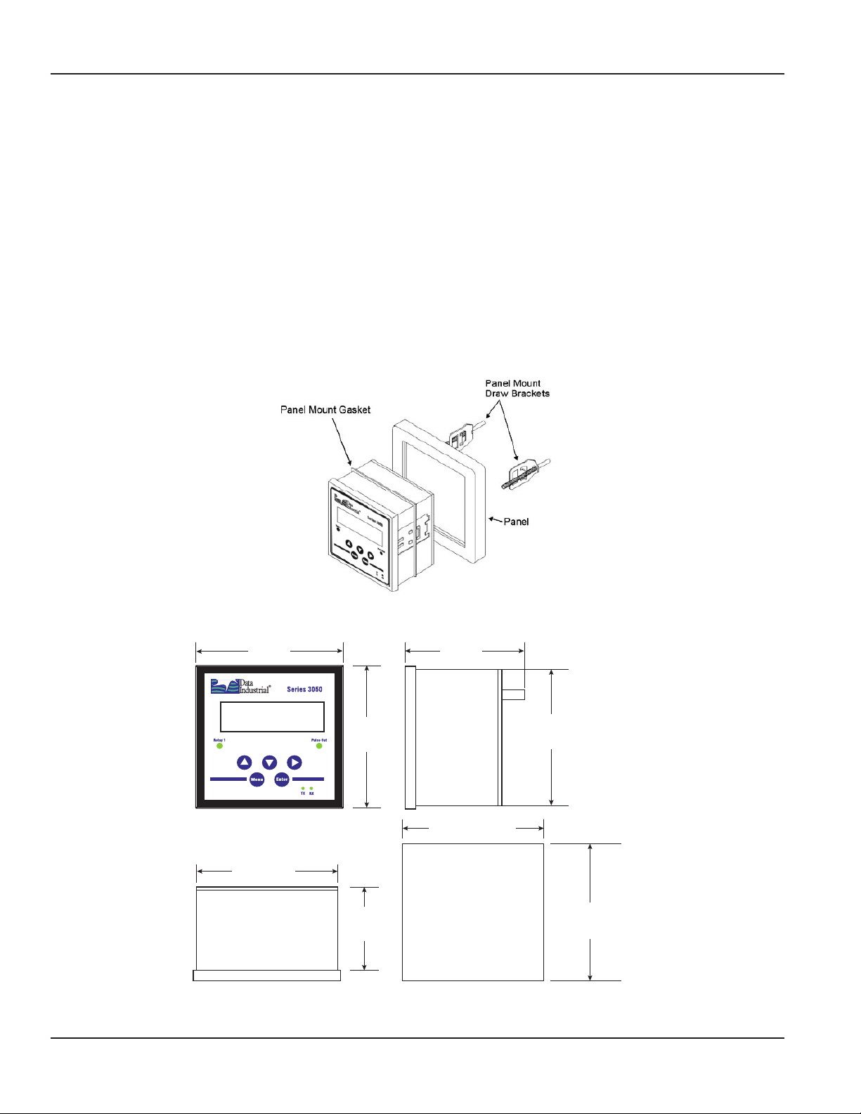
Panel Mount Installation
The Series 3050 BTU flow monitor panel-mount model is designed for through-panel mounting, which allows access to the
back of the unit. The monitor is secured to the panel by two draw brackets shown in Figure 1 below. Also refer to Figure 2 for
monitor and panel cutout dimensions.
3.78 in.
(96 mm)
3.49 in.
(88.7 mm)
TOP
Figure 1: Panel mounting
3.23 in.
(82 mm)
5
3.78 in.
(96 mm)
2.21 in.
(56 mm)
Figure 2: Panel-mount dimensions and panel cutout
SIDE
3.57…3.60 in.
(90.6…91.4 mm)
PANEL
CUTOUT
3.49 in.
(88.7 mm)
3.57…3.60 in.
(90.6…91.4 mm)
Page 6 June 2018DSY-UM-01668-EN-02
Page 7
Installation
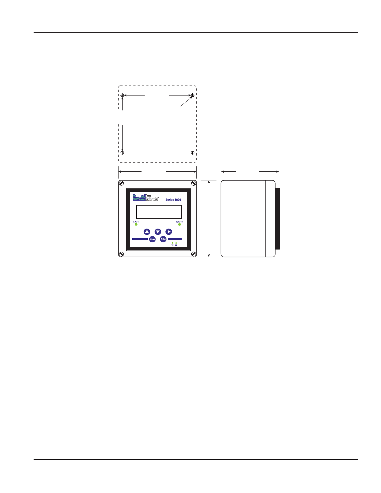
Wall Mount Installation
The Series 3050 BTU flow monitor wall-mount model is designed to mount onto a wall with four bolts or screws. The
mounting hole pattern and box dimensions for the Series 3050 BTU flow monitor NEMA4 waII-mount model are shown in
Figure 3.
4.33 in.
(110 mm)
1/8 in.
3.54 in.
(90 mm)
MOUNTING TEMPLATE
(3.2 mm)
WALL
4.80 in.
(122 mm)
4.72 in.
(120 mm)
Figure 3: Wall-mount dimensions and cutout
3.62 in.
(92 mm)
SIDE
Page 7 June 2018 DSY-UM-01668-EN-02
Page 8
Installation
Electrical Installation
Power Supply Wiring
The Series 3050 BTU flow monitor requires 12…24 V DC/AC to operate. Check the "Specifications" on page 30 for DC current
draw and AC Volt-Amp requirements.
Always use a fused circuit.
Connect the positive of the power supply to the flow monitor terminal marked (ACL/DC+), and connect the negative of the
power supply to the flow monitor terminal marked (ACC/DC-).
If a Badger Meter plugin power supply (Model A-1028) is being used, connect the black-white wire to the terminal marked
(ACL/DC+) and the black wire to the terminal marked (ACC/DC-).
POWER
Earth
LV AC/DC (-)
LV AC/DC (+)
3
2
1
Ground wire should be heavy gauge and as short as possible.
(+) (-)
12 . . . 24V DC
Power
Supply
Figure 4: Power supply wiring
or
(Line) (Com)
12 . . . 24V AC
Power
Supply
Earth
or
Panel
Ground
Page 8 June 2018DSY-UM-01668-EN-02
Page 9
Installation
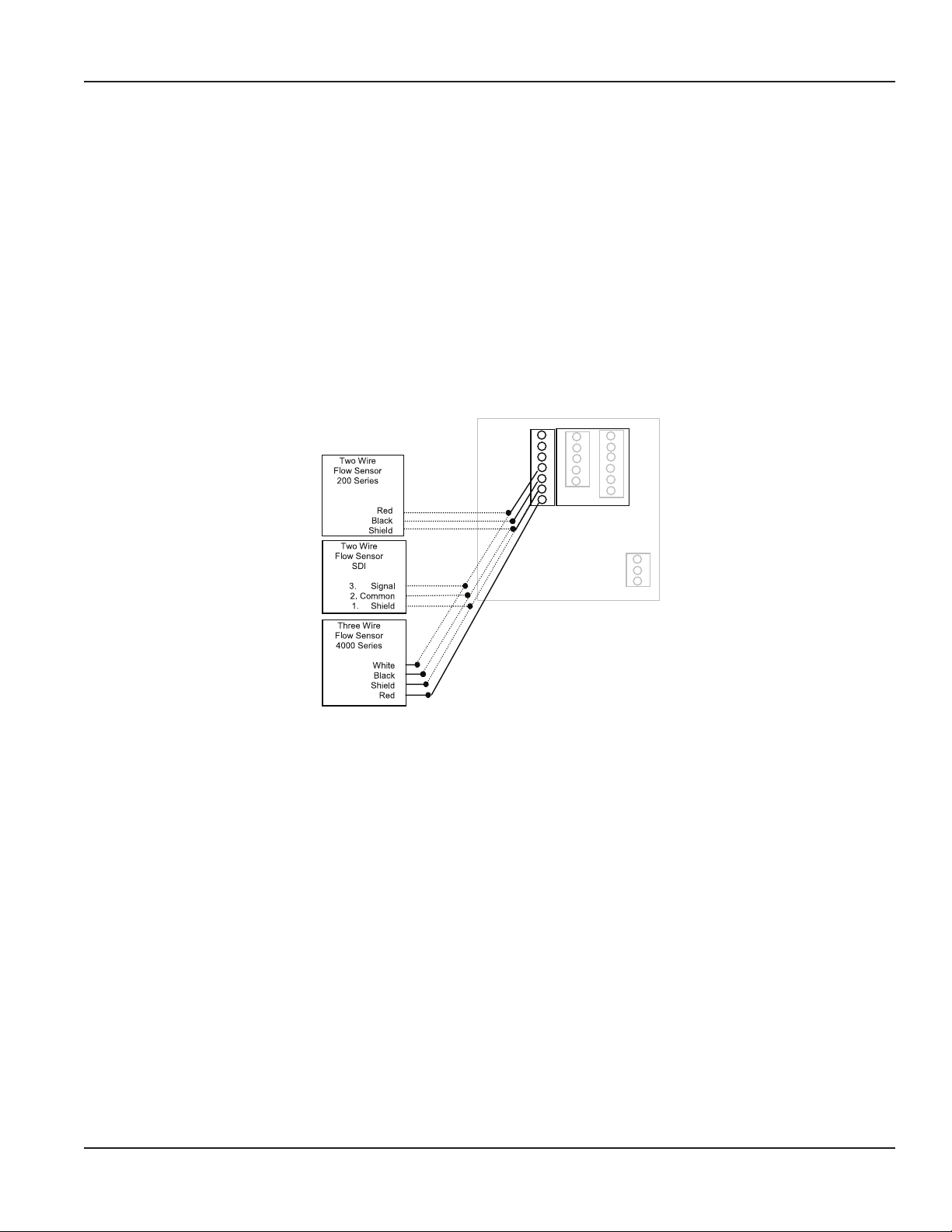
Flow Sensor Wiring
The Series 3050 flow sensor inputs are extremely versatile, designed to accept either two-wire or three-wire pulse inputs
(Badger Meter 200 Series, SDI or 4000 Series) or Analog inputs. Although different rear panel terminals are used, all
parameters are set with the LCD/keypad interface. There are no internal or external jumpers, switches or potentiometers to
move or adjust.
The following pulse input types are accommodated:
• Pulse-DI: Used for all Badger Meter Data Industrial Flow Sensors. Provides an internal pullup resistor and uses K and
“Offset” values for calibration.
• Pulse–K Factor: Accepts non zero-crossing inputs but provides no internal pullup, classical K ( pulses/gallon) values for
calibration.
• Pullup-K Factor: Provides an internal pullup resistor and uses classical K (pulses/gallon) values for calibration.
OTE:N All the above pulse input types wire the same as shown in Figure 5 on page 9. See the "Programming Flowcharts"
on page 18 through page 25 for required input configuration.
1 ANALOG IN+
2 ANALOG IN3 SHIELD
4 SENSOR IN
5 GND
6 SHIELD
7 SENSOR PWR
Figure 5: Badger Meter flow sensor wiring examples (two- and three-wire pulse types)
Page 9 June 2018 DSY-UM-01668-EN-02
Page 10
Installation
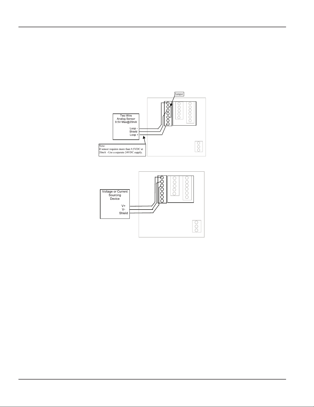
Analog Input
As an alternative to the pulse inputs, the Series 3050 BTU flow monitor can accept an Analog input. The input is non-isolated,
but can accept 0…1V DC, 0…5V DC, 0…10V DC, 0…20 mA and 4…20 mA with both factory-defined and custom units
of measure.
Low impedance 100 Ω input for current inputs optimizes performance and flexibility or loop power supplies. Both the
low-end and high-end scaling are independent and can be field-configured.
OTE:N See the "Programming Flowcharts" on page 18 through page 25 for required input configuration.
1 ANALOG IN+
2 ANALOG IN3 SHIELD
4 SENSOR IN
5 GND
6 SHIELD
7 SENSOR PWR
Figure 6: 4…20 mA analog loop powered wiring
1 ANALOG IN+
2 ANALOG IN3 SHIELD
4 SENSOR IN
5 GND
6 SHIELD
7 SENSOR PWR
Figure 7: Voltage or current sourcing analog inputs
Page 10 June 2018DSY-UM-01668-EN-02
Page 11

Flow Sensor
Installation
Temperature Input
The Series 3050 BTU flow monitor can accept inputs from either a pair of thermistors or RTDs. The inputs are labeled T1 and
T2. Since the T1 sensor is used to convert the volumetric flow (Example: GPM) to the mass flow (Example: Lbs/Hr) used in the
BTU calculations, the sensor connected to T1 should be in the same supply or return line as the flow sensor.
The temperature inputs of the flow monitor are extremely versatile. In addition to the factory default two-wire 10k @ 77° F
Type II Thermistors and three-wire 100 Ω platinum RTDs, the unit can be programmed in the field for a wide variety of custom
RTDs and thermistors. See the "Programming Flowcharts" on page 18 through page 25. Contact the factory for assistance
with any custom inputs.
1 TEMP 1 IN +
2 TEMP 1 IN 3 TEMP 1 GND
Jumpers
4 SHIELD
5 TEMP 2 GND
6 TEMP 2 IN 7 TEMP 2 IN +
2 W ire
Th ermistor
Located
in same
Supply
or
Return line
Flow Sensor
3 W ire
RTD
T1
Located
in same
Supply
or
Return line
as
2 W ire
Th ermistor
Figure 8: Wiring two-wire thermistors and RTDs
Dierent Color Wire
Same Colored 2 Wires
3 W ire
RTD
Figure 9: Wiring three-wire RTDs
1 TEMP 1 IN +
2 TEMP 1 IN 3 TEMP 1 GND
4 SHIELD
5 TEMP 2 GND
6 TEMP 2 IN 7 TEMP 2 IN +
Page 11 June 2018 DSY-UM-01668-EN-02
Page 12

Installation
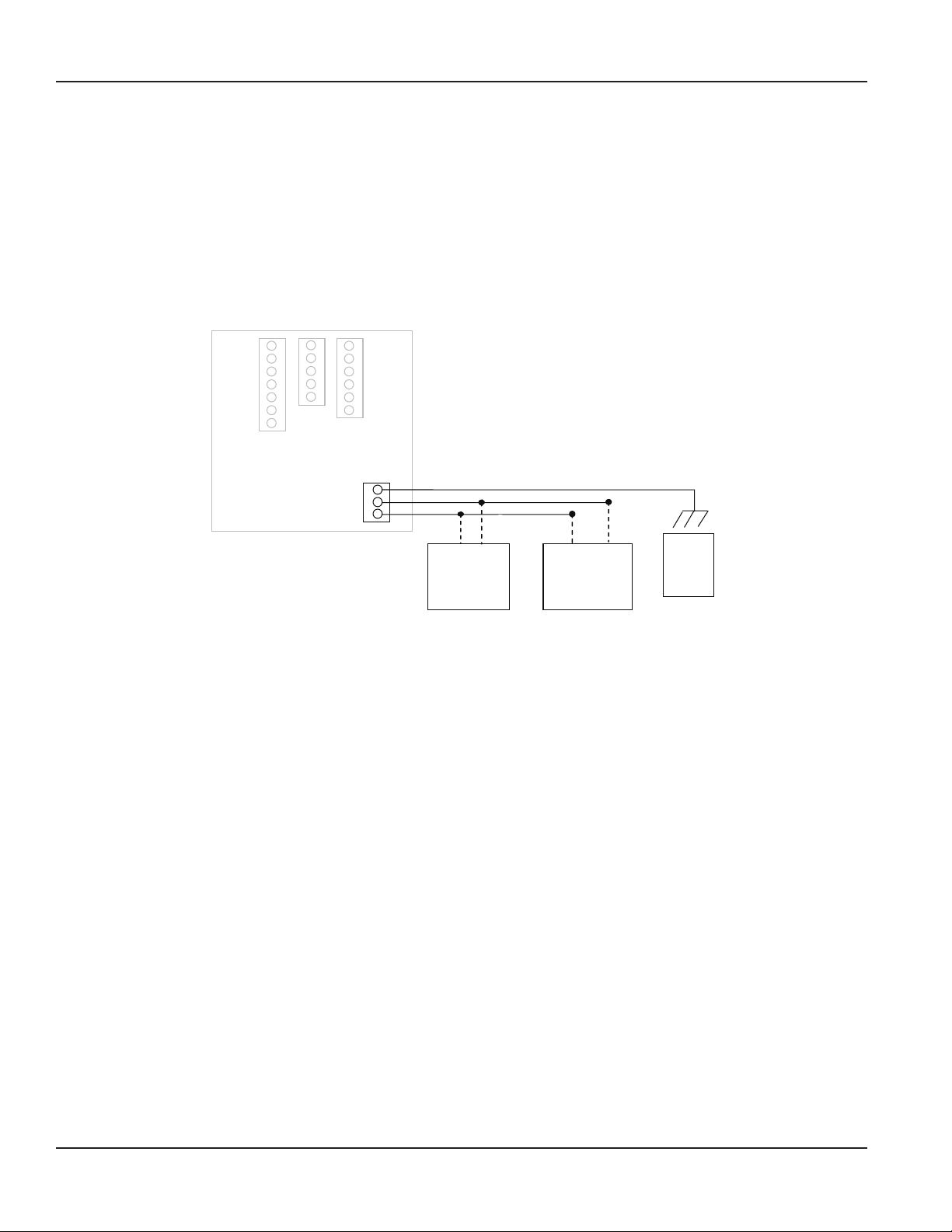
Solid-State Switch and Form C Output Wiring
The Series 3050 BTU flow monitor has one Normally Open (N.O.) solid-state switch, and one solid-state Form C relay.
See the "Specifications" on page 30 for maximum voltage and current ratings for each type output. These outputs are
completely independent, electrically isolated, and can be programmed as either Pulse or Setpoint outputs.
When the Totalizer function is selected, the unit of measure and resolution are independent from the displayed units and can
be programmed where one pulse occurs once every 0000000.1…999999999.0 of units selected, with any pulse width from
0001…9999 mS.
When the Alarm is selected as the unit of measure and the resolution is independent from the displayed units, it allows the
unit to be programmed as either a high or low rate Setpoint. Since the Setpoint, Release Point and their associated time delays
are fully independent, this output can be either a classical high rate or low rate alarm, depending on the settings selected.
When design planning, keep in mind that although both of these outputs can be programmed as alarm points only, the relay
provides both N.O. and N.C. contacts. The switch is a simple N.O. contact.
Example of High Flow Setpoint Control
The Setpoint must be a value greater than the Release Point.
The relay output will have continuity between its N.C. terminal and COM until the flow has exceeded the Setpoint (SETPT) for
a continuous period of time exceeding the Setpoint Delay (SDLY), at which time the N.C. connection will open and the N.O.
contact will have continuity to the COM terminal. When the flow has dropped below the Release Point (RELP) for a continuous
period of time exceeding the Release Point Delay (RDLY), the relay states will return to their original states. If the latch has been
set to ON, the relay will not release until manually reset once the Setpoint and Setpoint Delay have been satisfied. Sources for
the Setpoint control can be Flow Rate, Energy Rate, T1, T2 or Delta T.
Example of Low Flow Setpoint Control
The Setpoint must be a value less than the Release Point.
The relay output will have continuity between its N.C. terminal and COM until the flow drops below the Setpoint (SETPT)
for a continuous period of time exceeding the Setpoint Delay (SDLY), at which time the N.C. connection will open and the
N.O. contact will have continuity to the COM terminal. When the flow has again risen above the Release Point (RELP) for a
continuous period of time exceeding the Release Point Delay (RDLY), the relay states will return to their original states. If
the latch has been set to ON, the relay will not release until manually reset once the Setpoint and Setpoint Delay have been
satisfied. Sources for the Setpoint control can be Flow Rate, Energy Rate, T1, T2 or Delta T.
1 RELAY 1 NO
2 RELAY 1 NC
3 RELAY 1 COM
4 PULSE 1 OUT
5 PULSE 2 OUT
Figure 10: Relay and switch wiring examples
Page 12 June 2018DSY-UM-01668-EN-02
Page 13

Figure 11: Relay and switch wiring examples (continued)
Chiller control based on high energy usage with indication.
1 RELAY 1 NO
2 RELAY 1 NC
3 RELAY 1 COM
4 PULSE 1 OUT
5 PULSE 2 OUT
1 RELAY 1 NO
2 RELAY 1 NC
3 RELAY 1 COM
4 PULSE 1 OUT
5 PULSE 2 OUT
Installation
Figure 12: Relay and switch wiring examples (continued)
Chiller control based on low temperature warning with indication.
Page 13 June 2018 DSY-UM-01668-EN-02
Page 14

Installation
OUTPUT OPTION CARD
If the Series 3050 BTU flow monitor was ordered with the Output Option card, it will have these additional outputs:
• Analog Output ( 0…20 mA or 4…20 mA ) that can be converted externally to 0…5V DC, 1…5V DC with a 250 Ω resistor;
or 0…10V DC or 2…10V DC with a 500 Ω resistor. A 15V DC power supply is provided to permit current sinking or sourcing.
The Series 3050 BTU flow monitor has special software that permits the Analog output.
• USB for direct access to a computer using a standard mini-USB cable.
• RS-485 for fully addressable Modbus or BACnet communication.
Analog Output
+
1 RS485 B
2 RS485 A
3 RS485 GND
4 LOOP +
5 LOOP 6 GND
-
RS-485 Output
Figure 13: Current sourcing analog output
1 RS485 B
2 RS485 A
3 RS485 GND
4 LOOP +
5 LOOP 6 GND
Figure 14: Current sinking analog output
1 RS485 B
2 RS485 A
3 RS485 GN D
4 LOOP +
5 LOOP 6 GND
Model 3700
Model 345WT
or other
MODBUS
Master
Device
Shield
RS485 -
RS485 +
Figure 15: RS-485 output wiring
Page 14 June 2018DSY-UM-01668-EN-02
Page 15

Installation
Modbus Registers
All of the following are available as Input Registers. Data is formatted as a float (CD AB) and each data point isstored in two
Modbus registers.
Addr Function
1 Flow 1 Rate (GPM)
3 Flow 2 Rate (GPM)
5 Flow 1 Total (gallons)
7 Flow 2 Total (gallons)
9 Energy Rate (BTU/min)
11 Energy Total (BTU)
13 Batch 1 Count
15 Batch 2 Count
17 Temp 1 (deg F)
19 Temp 2 (deg F)
21 Temp Delta (T2-T1)
USB Port
Use
Figure 16: USB analog output
Standard Cable
USB Type A Male
to
Type Mini B 5 Pin Male
Connect to
Computer USB
Com Port
OTE:N Communication via the USB port requires a terminal emulator. This port is part of the Analog Output Option card. See
"USB Communication" on page 26 for instructions on how to use this port.
Page 15 June 2018 DSY-UM-01668-EN-02
Page 16

Display and Keypad
DISPLAY AND KEYPAD
The Series 3050 BTU flow monitor has a two line by 16-character display with two modes of operation and 5 keys on the front
panel for programming.
Menu
Enter
When the Series 3050 BTU flow monitor is first powered up, it runs through internal self checks while displaying
“Badger Meter DIC Initializing." At the end of this cycle its normal mode display will appear.
In the normal mode, if still using the factory defaults, flow rate will be displayed on the top line, and flow total displayed on
the bottom. Both lines can be custom-defined in the field as desired. In the normal mode the Enter key has no function.
1-Switch to main menu
2-Backward/Previous menu
1-Save value
2-Forward/Next menu
Up Arrow
Down
Arrow
Right
Arrow
1-Select Menu option
2-Increase numerical value
1-Select Menu option
2-Decrease numerical value
1-Select Menu option
2-Move cursor to the right
0.0 GPM
0.0 gal
Menu Enter
Figure 17: Normal mode display
The other mode is the program mode, used to configure the unit. Press Menu to enter and exit this mode. See "Programming"
on page 17.
RESET SETUP DIAG
Menu Enter
Figure 18: Program mode display
Page 16 June 2018DSY-UM-01668-EN-02
Page 17

Flow 1 units
Programming
PROGRAMMING
With the normal mode display showing, press Menu to enter the programming mode. In this mode, you use the three arrow
keys () on the selection screens to select the option displayed above the key, and on the option list screens to scroll up
or down a list of choices, like a pull-down menu. Most screens presenting choices show three choices, one for each arrow key.
When the number of choices exceeds three, a small arrow () appears on the upper right of the display, indicating there are
more choices on that level. Press Enter to toggle to the next set of choices. Once the selection has been made, press Enter to
complete the selection. Press Menu again to return to the normal mode display.
Selection Screens
Most selection screens show three choices, one for each arrow () key. When the number of choices exceeds three, a
small arrow ( ) appears on the upper right side of the display, indicating there are more choices on that level. Press Enter to
view the next set of choices.
For example, pressing Menu from the normal mode screen shows the RESET SETUP DIAG screen. Pressing the Up Arrow key
brings up the RESET screens. Pressing the Down Arrow key brings up the SETUP screens and pressing the Right-Arrow key
brings up the DIAG (diagnostic) screens. In this example, if you press the Down Arrow key, this screen appears:
SETUP
PWORD DSPY FLOW1
Menu Enter
Figure 19: Selection screen
Option List Screens
Units of measure is an example of an options list screen.
Press the Up Arrow key to scroll up the list or press the Down Arrow key to scroll down the list. In this case, the list starts with
GPM; gal/s; gal/hr;…LPM;…. and ends with Custom Units.
With a selection highlighted, press Enter to complete the selection or press Menu to leave the selection unchanged. The
Right-Arrow key has no function on this type of screen.
GPM
Menu Enter
Figure 20: Option list screen
Data Screens
Some screens are data entry screens. For example, the Setpoint or Custom Unit screens.
When a data entry screen is active, the current value displays. The left-most digit flashes. Press the Up Arrow key to increase
the value. Press the Down Arrow key to reduce the value. If the decimal point is flashing, press the Up Arrow key to move the
decimal point to the right or press the Down Arrow key to move the decimal point to the left.
Setpoint
1.00000000
Menu Enter
Figure 21: Data screen
Page 17 June 2018 DSY-UM-01668-EN-02
Page 18

Programming
Programming Flowcharts
RESET SETUP DIAG
Reset ow 1?
OK CANCEL
Reset ow 1?
Reset
Require setup PW
YES [NO]
RESET
FLOW1 BTU
Password setup
ENAB SETUP RESET
Setup password
0000
Reset BTU total?
OK CANCEL
Reset BTU total?
Reset
Reset password
0000
Enter password
0000
SETUP
PWORD DSPY FLOW1
Go to
Flow
Inputs
DISPLAY
LINE1 LINE2 RATE
DIAG
MODL# SER# REV#
Model #:
3050xx
Serial #:
######
SETUP
BTU RLY1 PULSE
Go to BTU &
Temperature
Inputs
DIAG ERROR
Firmware rev:
v1.2.xx
Error codes
000 000 000 000
SETUP
AOUT1 COMM
Go to
Analog
Out
Go to Relays &
Pulse Outputs
Go to RS485
Communications
Port
LINE1
Flow 1 Rate
Flow 1 Total
BTU Rate
BTU Total
Temp 1 and 2
T2 - T1
Page 18 June 2018DSY-UM-01668-EN-02
LINE2
Flow 1 Rate
Flow 1 Total
BTU Rate
BTU Total
Temp 1 and 2
T2 - T1
Update rate
+0.50000000 sec
Page 19

Flow Inputs Flowchart
Flow 1 setup
RATE TOTAL SENSR
Programming
Flow 1 rate
UNITS #.DIG CUST
Flow 1 # digits
0
1
2
Flow X units
GPM
gal/s
gal/hr
Mgal/day
L/s
LPM
L/hr
ft3/s
ft3/min
ft3/hr
m3/s
m3/min
m3/hr
acre-ft/s
acre-ft/min
acre-ft/hr
bbl/s
bbl/min
bbl/hr
Custom units
Custom units
LABEL CONV
1 unit =
+0.00000001 gpm
.
.
.
999999999.
Flow 1 total
UNITS #.DIG CUST
Total X units
gal
Mgal
L
ft3
m3
acre-ft
bbl
Custom units
Total 1 # digits
Custom units
LABEL CONV
0
1
2
Enable password?
YES [NO]
Enable password?
[YES] NO
1 UNIT =
+0.00000001 gal
.
.
.
999999999.
Flow 1 total
RESET
Reset ow total
PASSWD RESET
Reset total NOW?
OK CANCEL
Unit label
?
>
=
<
;
:
9999999999
8888888888
.
.
.
1
0000000000
/
.
,
+
*
)
(
'
&
%
$
"
!
Continued
at A on
next page.
{
z
y
x
.
.
.
c
b
a
`
_
^
]
¥
[
ZZZZZZZZZZ
Y
X
.
.
.
J
BBBBBBBBBB
AAAAAAAAA
Page 19 June 2018 DSY-UM-01668-EN-02
Page 20

Programming
Flow Inputs Flowchart (continued)
Continued
A
from previous
page.
Sensor 1 type
Flow 1 sensor
TYPE xxxxxxxx
Flow 1 sensor
Pulse DI
TYPE AVG DICAL
DI Sensor Cal.
KNUM OFFSET
Pulse K-Factor
Pullup K-Factor
Sine K-Factor
Analog
Flow x units
GPM
gal/s
gal/hr
Mgal/day
L/s
LPM
L/hr
ft3/s
ft3/min
ft3/hr
m3/s
m3/min
m3/hr
acre-ft/s
acre-ft/min
acre-ft/hr
bbl/s
bbl/min
bbl/hr
Custom units
Flow 1 sensor
TYPE AVG KFACT
Flow 1 sensor
TYPE ANALOG
Analog ow 1
UNITS RANGE HIGH
Analog x range
0 to 1V
0 to 5V
0 to 10V
0 to 20 mA
4 to 20 mA
Max reading = ?
0.00000001
999999999.
Flow 1 timeconst
+0.00000001 sec
.
.
.
100.000000
Flow 1 timeconst
+0.00000001 sec
.
.
.
100.000000
Analog ow 1
LOW CAL
Min reading = ?
0.00000001
.
.
.
999999999.
Sampling
XXXXXXXXXXXX
DI sensor K num
1.00000000
.
.
.
999999999.
K-Factor
1.00000000
.
.
.
999999999.
0V = xxxx
Read Factory
1V = xxxx
Read Factory
5V = xxxx
Read Factory
10V = xxxx
Read Factory
.
.
4 mA = xxxx
.
Read Factory
20 mA = xxxx
Read Factory
DI Sensor Ost
-999999999.
.
.
.
-0.00000001
+0.00000001
.
.
+999999999.
Page 20 June 2018DSY-UM-01668-EN-02
Page 21

BTU and Temperature Inputs
SETUP
BTU RLY1 PULSE
BTU Monitor
RATE TOTAL SENSR
Programming
BTU rate display
UNITS #.DIG CUST
Displayed digits
0
1
2
BTU rate units
BTU/min
kBTU/hr
Custom units
J/sec
Tons
kW
Custom units
LABEL CONV
1 unit = ? kBTU/hr
+0.00000001 gpm
.
.
.
999999999.
BTU 1 total
UNITS #.DIG CUST
Totalizer units
BTU
kBTU
MBTU
kWh
MWh
kJ
Custom units
Displayed digits
0
1
2
Enable password?
YES [NO]
Enable password?
[YES] NO
Custom units
LABEL CONV
1 UNIT = ? BTU
+0.00000001 gal
.
.
.
999999999.
Totalizer
RESET
Reset BTU total
PASSWD RESET
Reset total NOW?
OK CANCEL
Unit label
?
>
=
<
;
:
9999999999
8888888888
.
.
.
1
0000000000
/
.
,
+
*
)
(
'
&
%
$
"
!
Continued
at A on
next page.
{
z
y
x
.
.
.
c
b
a
`
_
^
]
¥
[
ZZZZZZZZZZ
Y
X
.
.
.
J
BBBBBBBBBB
AAAAAAAAA
Page 21 June 2018 DSY-UM-01668-EN-02
Page 22

Programming
BTU and Temperature Inputs (continued)
Continued
A
from previous
page.
BTU Monitor
RATE TOTAL SENSR
Temp Sensor
TYPE TUNIT TMODE
Temp units
Sensor type
DI Thermistor
DI RTD
Cust. Thermistor
Custom RTD
No Sensor
Totalizing
T1 < T2
T1 > T2
Absolute
°F
°C
Thermistor calib
A0 A1 A3
A0*10^4
+0.000000000
A01*10^4
+0.000000000
RTD calib
A0 A1 A2
A0
+0.000000000
A1
+0.000000000
Temp Sensor
T2ADJ CUST SHC
Temp 2 Adj
-10.00000000 °F
.
.
.
+10.00000000 °C
A03*10^4
+0.000000000
A2*10^5
+0.000000000
Current Source
1 mA
Specic Heat
+0.0000000 °F
.
.
.
+99999999 °C
Temp Sensor
CSRC SLOPE OFFSET
Slope XX µA
EDIT NEXT FACTORY
Slope XX µA
+0.0000000
.
.
.
+99999999
Slope
1 mA
8 µA
40 µA
200 µA
Oset
T1 T1COMP T2 T2COMP
Oset
EDIT NEXT FACTORY
X Oset
+0.0000000
.
.
.
+99999999
X Oset
1 mA
8 µA
40 µA
200 µA
Factory reset?
YES [NO]
Factory reset?
YES [NO]
Temp Sensor
CAL
Calibrate
YES FACTORY
Factory reset?
CONFIRM
Jumper T1 and T2
PROCEED
Page 22 June 2018DSY-UM-01668-EN-02
Page 23

Relays and Pulse Outputs Flowchart (Manual, Setpoint Rate and Pulse/Volume)
SETUP
RLY1 Pulse
Relay 1 (or Pulse)
FUNC xxxxx xxxxx
Manual Control
Programming
Relay 1 (or Pulse)
FUNC MANUAL
Totalizer
Alarm
Relay 1 (or Pulse)
FUNC INPUT UNITS
Relay 1 input
(or Pulse)
Flow 1 Rate
BTU Rate
Temperature 1
Temperature 2
T2 - T1
}
Relay 1 (or Pulse)
FUNC INPUT UNITS
Totalizer input
Flow 1 Total
BTU Total
Relay 1 (or Pulse)
FUNC INPUT UNITS
Set point units
°F
°C
Pulse rate units
BTU
kBTU
MBTU
kWh
MWh
kJ
Custom units
Relay 1 (or Pulse)
FUNC INPUT UNITS
Set point units
kBTU/hr
BTU/min
kW
Tons
J/sec
Custom units
Flow total units
gal
Mgal
L
ft3
m3
acre-ft
bbl
Custom units
Relay 1 (or Pulse)
FUNC INPUT UNITS
Relay 1 Latch?
ON [OFF]
Flow x units
GPM
gal/s
gal/hr
Mgal/day
L/s
LPM
L/hr
ft3/s
ft3/min
ft3/hr
m3/s
m3/min
m3/hr
acre-ft/s
acre-ft/min
acre-ft/hr
bbl/s
bbl/min
bbl/hr
Custom units
Relay 1 (or Pulse)
RATE CTIME
1 pulse = ?
0.00000001
.
.
.
999999999.
Relay 1 (or Pulse)
LATCH SETPT RELP
Set point
-0.00000001
.
.
.
+999999999.
Release point
Time closed
0001 mS
9999 mS
-0.00000001
+999999999.
Relay 1 (or Pulse)
ON [OFF]
Relay 1 (or Pulse)
[ON] OFF
.
.
.
Relay 1 (or Pulse)
SDLY RDLY
Trigger delay
0000000 mS
.
.
.
10000000 mS
Release delay
0000000 mS
.
.
.
10000000 mS
.
.
.
Page 23 June 2018 DSY-UM-01668-EN-02
Page 24

Programming
Analog Output Flowchart
SETUP
AOUT1 COMM
Analog output 1
FUNC RANGE SCR
Flow Rate
BTU Rate
Temperature
Analog output 1
FUNC RANGE SCR
Analog
output
range
0-20 mA
4-20 mA
Analog output 1
FUNC RANGE UNIT
Analog output range
0-20 mA
4-20 mA
Analog output 1
FUNC RANGE SCR
Analog
output
range
0-20 mA
4-20 mA
Drive source
Temp 1
Temp 2
T2 - T1
Drive source
Flow 1 Rate
Analog 1 units
kBTU/hr
BTU/min
kW
Tons
J/sec
Custom units
Analog output 1
UNITS LOW HIGH
0 mA = ?
0.0000000
Analog 1 units
°F
°C
0 mA = ?
0.0000000
Analog output 1
CAL
20 mA = ?
0.0000000
Analog output 1
LOW HIGH CAL
20 mA = ?
0.0000000
Adjust 4 mA
12107 FACTRY
Adjust 20 mA
60748 FACTRY
Analog output 1
UNITS LOW HIGH
Analog 1 units
GPM
gal/s
gal/hr
Mgal/day
L/s
LPM
L/hr
ft3/s
ft3/min
ft3/hr
m3/s
m3/min
m3/hr
acre-ft/s
acre-ft/min
acre-ft/hr
bbl/s
bbl/min
bbl/hr
Custom units
0 mA = ?
0.0000000
20 mA = ?
0.0000000
Analog output 1
CAL
Adjust 4 mA
12107 FACTRY
Adjust 20 mA
60748 FACTRY
PID
Analog output 1
FUNC RANGE SCR
Analog output range
0 to 20 mA
4 to 20 mA
Drive source
Flow 1 Rate
Flow 2 Rate
Analog output 1
UNITS SETPT P
Flow x units
GPM
gal/s
gal/hr
Mgal/day
L/s
LPM
L/hr
ft3/s
ft3/min
ft3/hr
m3/s
m3/min
m3/hr
acre-ft/s
acre-ft/min
acre-ft/hr
bbl/s
bbl/min
bbl/hr
Custom units
PID P const
+000.000
+999.000
PID Set point
-0.00000000
+999.99999
Analog output 1
I D LOW
PID I const
+000.0000
.
.
.
+999.9999
.
.
.
4 mA = ?
+000.0000
.
.
.
+999.9999
PID D const
+000.000
+999.000
.
.
.
.
.
.
Analog output 1
HIGH
20 mA = ?
+000.0000
.
.
.
+999.9999
Adjust 4 mA
12107 FACTRY
Analog output 1
CAL
Adjust 20 mA
60748 FACTRY
Page 24 June 2018DSY-UM-01668-EN-02
Page 25

RS485 Communication Port Flowchart
Comm
NET BAUD ADDR
Programming
Network
Disable
MODBUS
BACnet/MSTP
Comm
NET
Comm
NET BAUD ADDR
Network
MODBUS
Baud Rate
300
1200
2400
9600
19200
38400
76800
Comm
NET BAUD ADDR MAX DEVID
MODBUS Address
001
.
.
.
255
Network
BACnet/MSTP
Baud Rate
Auto
9600
19200
38400
76800
MSTP Address
001
127
MSTP Max master
.
.
.
001
127
Device Instance
.
.
.
00000000
.
.
.
99999999
Page 25 June 2018 DSY-UM-01668-EN-02
Page 26

Programming
USB Communication
If you order the Series 3050 BTU flow monitor with an Analog Output Option card, a five-pin USB connector is also included.
As much as possible, the commands mimic the use of the front panel controls.
To use this feature, you need:
• A PC with USB ports and any terminal emulator software
• Windows 7, 8 or Windows XP operating system
• FTDI Virtual COM port drivers from http://www.ftdichip.com/FTDrivers.htm
• A USB 2.0 A to Mini-B 5-pin cable
To communicate using terminal:
1. Make sure that the Series 3050 BTU flow monitor has a Mini-B ve-pin connector on the back panel. The Series 3050 BTU
flow monitor must have an Analog Output Option card installed and the monitor marked Series # 3050-1x.
2. Check that the appropriate FTDI Virtual COM port drivers are installed on your computer.
3. Plug the USB 2.0 A end of the cable into a USB port on your computer. Plug the Mini-B five-pin end into the back of the
Series 3050 BTU flow monitor.
4. Run any terminal emulator and create a new connection with the proper COM port selected. Use the Windows Device
Manager to locate the COM port. The 3050 device will show up under Ports and will be called USB Serial Port.
5. Congure this port as:
◊ Bits per second: 38400
◊ Data bits: 8
◊ Parity: None
◊ Stop bits: 1
◊ Flow control: None
6. When connected, a greater-than (>) symbol appears in the upper left corner of the main HyperTerminal display screen.
Press Enter. Both the Rx and Tx LEDs on the front of the flow monitor ash once, and the “Badger Meter DIC … Software
Version…” text message appears.
The Series 3050 BTU flow monitor is now communicating, ready to take commands from the lists on the following pages.
Page 26 June 2018DSY-UM-01668-EN-02
Page 27

Command Lists
COMMAND LISTS
USB Command List
In the list below, brackets indicate an argument, specifying its type
and value range. For instance [0-18] stands for any number between
0 and 18 (inclusive).
Example: “display line1 = 1” sets Line 1 of the display to display #1,
which happens to be the totalizer for flow channel 1.
Diagnostics:
id – show model number & software version
echo [on/o] – turn on/o interactive command line:
with echo o, this interface is more
amenable to scripting; it still accepts the same
commands.
Any command entered without an “ = “ sign and
variable will display the current setting.
Example: Typing “display line1” returns “0” which is the variable for Flow rate.
read ow [1-2] – read the current ow on channel 1 or 2 in
GPM.
read ow [1-2] total – read the current total ow on channel
1 or 2 in gallons.
Display Configuration
display line1 = [0-18] – set line 1 of the display
display line2 = [0-18] – set line 2 of the display
valid options are:
0: ow 1 rate
1: ow 1 total
2: ow 2 rate
3: ow 2 total
4: ow 1+2 rate
5: ow 1+2 total
6: ow 1-2 rate
7: ow 1-2 total
8: ow 2-1 rate
9: ow 2-1 total
14: BTU rate
15: BTU total
16: temperature 1&2
17: temperature 1-2
display urate = [0.1-10] – set the update rate of the display, in
seconds
Flow Input Channel Configuration
ow [1-2] sensor type = [0-4] – ow sensor type:
0: PulseDI,
1: PulseKFactor,
2: PullupKFactor
3: Analog
ow [1-2] sensor dical k = [x] – DI-type ow sensor k
ow [1-2] sensor dical o = [x] – DI-type ow sensor oset
ow [1-2] sensor kfact = [x] – K factor for non-DI sensors
ow [1-2] sensor analog units = [0-19] – ow units for analog input
ow [1-2] sensor analog range = [0-4] – current range for
analog input
ow [1-2] sensor analog high = [x] – ow rate @max current
ow [1-2] sensor analog low = [x] – ow rate @min current
ow [1-2] sensor avg = [0-100] – averaging "time constant," in
seconds:
ow [1-2] rate units = [0-19] – ow (channel) rate units to display.
0: GPM
1: gal/s
2: gal/hr
3: Mgal/day
4: L/s
5: LPM
6: L/hr
7: ft3/s
8: ft3/min
9: ft3/hr
10: m3/s
11: m3/min
12: m3/hr
13: acreft/s
14: acreft/min
15: acreft/hr
16: bbl/s
17: bbl/min
18: bbl/hr
19: Custom
ow [1-2] rate ndigits = [2-10] – number of decimal places to show
for ow rate
ow [1-2] rate custom label = [string] – set the label for custom units
ow [1-2] rate custom conv = [0-100] – conversion factor for
custom units
ow [1-2] total units = [0-7] – set the totalizer units to display
0: gal
1: Mgal
2: L
3: ft3
4: m3
5: acreft
6: bbl
7: Custom
Page 27 June 2018 DSY-UM-01668-EN-02
Page 28

Command Lists
BTU Configuration
BTU rate units = [0-5] – set the BTU rate units:
0: kBTU/hr
1: BTU/min
2: kW
3: TR
4: J/s
5: Custom
BTU rate ndigits = [2-10] – number of decimal digits to display
BTU rate custom label = [string] – BTU rate custom unit label
BTU rate custom conv = [0-100] – custom unit conversion factor
BTU total units = [0-6] – BTU totalizer units:
0: BTU
1: kBTU
2: MBTU
3: kWh
4: MWh
5: kJ
6: Custom
BTU total ndigits = [2-10] – number of decimal digits to display
BTU total custom label = [string] – BTU totalizer custom unit
label
BTU total custom conv = [0-100] – custom unit conversion
factor
BTU total mode = [0-2] – totalizer mode:
0: Heating
1: Cooling
2: Heating & Cooling
BTU sensor type = [0-4] – temperature sensor type:
0: DI Thermistor
1: DI RTD
2: Custom Thermistor
3: Custom RTD
4: No sensor
BTU sensor correct_k = [0-10] – correction factor
BTU sensor temp_unit = [0-1] – temperature units to display
0: deg F
1: deg C
BTU sensor t2adj = [-10-10] – t2a
Relay Output Configuration
relay [1-5] func = [0-9] – relay function; relay 5 is the pulse output
0: Totalizer
1: Alarm
2: Manual Control
relay [1-5] input = [0-8] – relay input; depends on source
for totalizer:
0: Flow 1 Total
for alarms:
0: Flow 1 Rate
relay [1-5] units = [0-19] – units on setpoints/rates; depends on src/
input
ow units: same as 'ow [1-2] rate units' above
volume units: same as 'ow [1-2] total units'
relay [1-5] manual = [on/o] – manually set relay on or o, if in
manual mode
relay [1-5] rate = [x] – totalizer rate
relay [1-5] ctime = [0-10000] – pulse width in milliseconds
relay [1-4] latch = [on/o] – turn on/o relay latching
relay [1-4] setpoint = [x]
relay [1-4] releasepoint = [x]
Analog Output Configuration
analogout [1-2] func = [0-3]
0: Flow rate
1: BTU rate
2: Temperature
3: PID control
analogout [1-2] src = [0-4]
for ow rate:
0: Flow 1 rate
1: Flow 2 rate
2: Flow sum
3: Flow 1-2
4: Flow 2-1
for BTU rate: not used
for temperature:
0: Flow rate
1: Temp 2
2: Temp Delta
for PID control:
0: Flow 1 rate
1: Flow 2 rate
analogout [1-2] range – [0-1]
0: 0-20mA
1: 4-20mA
analogout [1-2] low = [x] – value corresponding to 0 (or 4) mA
analogout [1-2] high = [x] – value corresponding to 20mA
analogout [1-2] setpoint = [x] – PID setpoint
analogout [1-2] P = [x] – PID constants
analogout [1-2] I = [x] – PID constants
analogout [1-2] D = [x] – PID constants
Page 28 June 2018DSY-UM-01668-EN-02
Page 29

Command Lists
RS485 Comm Port Configuration
comm baudrate = [0-7]
0: Auto
1: 300
2: 1200
3: 2400
4: 9600
5: 19200
6: 38400
7: 76800
comm mstpaddr = [0-127] – BACnet/MSTP address
comm maxmaster = [0-127] – BACnet/MSTP max master address
comm devinst = [x] – BACnet device instance ID
comm mbslaveaddr = [0-255] – Modbus slave address
Modbus
Addr Function
1 Flow 1 rate (GPM)
3 Flow 2 rate (GPM)
5 Flow 1 Total (gallons)
7 Flow 2 Total (gallons)
9 Energy Rate (BTU/min)
11 Energy Total (BTU)
13 Batch 1 Count
15 Batch 2 Count
17 Temp 1 (deg F)
19 Temp 2 (deg F
21 Temp Delta (T2-T1)
Troubleshooting
Trouble Codes
1 Relay 1 totalizer rate exceeded
2 Relay 2 rate exceeded
3 Relay 3 rate exceeded
4 Relay 4 rate exceeded
5 Pulse out rate exceeded
20 Error reading EEPROM on faceplate
21 Error writing EEPROM
22 Analog Input card missing
24 Temperature Input card missing
25 Invalid ow units congured
26 Invalid volume units congured
27 Bad input frequency
29 Internal error calculating ow rate
31 Error reading from analog input AD converter channel 1
32 Error reading from analog input AD converter channel 2
36 Error writing to analog input AD converter channel 1
37 Error writing to analog input AD converter channel 2
50 Error reading I2C address 0 (relays, buttons, and LEDs)
51 Error writing to I2C address 0
52 Error reading I2C address 1 (analog input card control lines)
53 Error writing I2C address 1
54 Error reading I2C address 2 (temperature input card control lines)
55 Error writing I2C address 2
71 Watchdog timer reset occurred
82 Fatal error initializing EEPROM
Page 29 June 2018 DSY-UM-01668-EN-02
Page 30

Flow Sensor Inputs
FLOW SENSOR INPUTS
Type Threshold Signal Input Frequency Pull-up Impedance Aux. Power Calibration
Pulse-DI 2.5V DC 30V DC 0.4 Hz…10 kHz 1K…12V DC — 12V DC @30mA K + Offset
Pulse K-factor 2.5V DC 30V DC 0.4 Hz…10 kHz — — 12V DC @30mA Pulse/Gal
Pull-up K-factor 2.5V DC 30V DC 0.4 Hz…10 kHz 1K…12V DC — 12V DC @30mA Pulse/Gal
Analog 4…20mA 10mVPP 50 mA Fused — — 100 Ω 12V DC @30mA Linear
Analog 0…20mA — 50 mA Fused — — 100 Ω 12V DC @30mA Linear
Analog 0…1V DC — 30V DC — — 100 Ω 12V DC @30mA Linear
Analog 0…5V DC — 30V DC — — 100 Ω 12V DC @30mA Linear
Analog 0…10V DC — 30V DC — — 100 Ω 12V DC @30mA Linear
SPECIFICATIONS
Voltage 12…24V DC/AC (limit: 8…35V DC); (limit: 8…28V AC)
Operating
Temperature
Storage Temperature –22…176° F (–30…80° C)
Weight Panel Mount: 12 oz
Pulse and Relays Both pulse and relay are fully functional as either totalizing or setpoint outputs
Pulse Electrical 1 Amp at 35V DC/30V AC Closed: 0.5 Ω at 1 Amp; Open: >108 Ω
Relay Electrical
Pulse/Unit Volume
(Totalizer)
Setpoint (Alarm)
Optional Analog
Output
USB Communication Provides complete access to all programming and operation features
RS-485
Communication
Accessories Programming kit; wall-mount kit
Temperature Inputs
Units of Measure
–4…158° F (–20…70° C)
Resistive Load:
5A @ 120V AC/30V DC
Driving Source: flow total,
BTU total
Driving Source: flow rate,
BTU rate, temperature 1,
temperature 2, delta T
Delay to Set: 1…9999 sec Release Point: 1.0000000…999999999 Delay to Release: 1…9999 sec
Driving Source: flow rate,
BTU rate, temperature 1,
temperature 2, delta T, PID
control
Supports Modbus and BACnet/MSTP
Two of 2-wire 10k type II thermistor; 25…170° F (–3.9…76.7° C) or custom field-defined
3-wire platinum 100Ω RTD; 25…250° F (–3.9…121.1° C) or custom field-defined
Unis of Measure: °F and °C
Zeroing: Compensate
for variances between
temperature elements by
adjusting T2 reading to match
T1 reading.
Rate
Total
Inductive Load:
1A @ 120V AC/30V DC
Rate: 1 pulse per 1.0000000…99999999
units
Units: Any predefined or custom unit Setpoint: 1.0000000…999999999
Range: 4…20 mA; 0…20 mA (isolated
current sinking or sourcing)
Energy Rate Units: kBTU/hr; BTU/min;
kW; Tons; J/Sec; and field programmed
custom units
Constant: Single point correction for
variances in specific heat of transfer
liquid.
US gpm; US gal/sec; gal/hr; US mgal/day; lps; lpm; lph; ft3/Sec; ft3/min; ft3/hr; m3/
sec; m3/min; m3/hr; acre-ft/sec; acre-ft/min; acre-ft/hr; bbl/sec; bbl/min; bbl/hr;
and field programmed custom units 0.00…999999999
US mgal; liters; ft3; m3; acre-ft; bbl; and field programmed custom units
0.00…999999999
DC current draw (~ 280 mA)
AC Power rating (~5 VA)
Contact Time: 1…9999 mS
Sinking: 30V DC @ 0 mA max.;
3V @ 20 mA min.
Sourcing: 600 W max load
Requirements: USB 2.0 A to Mini-B,
five-pin cable
Operating Mode: T1<T2; T1>T2;
absolute; Defines how reverse
energy flows are handled (T1 should
be installed in the same pipe as the
flow sensor)
Energy Total units: kBTU;
Mbtu; kWh; MWh; kJ; and field
programmed custom units
Page 30 June 2018DSY-UM-01668-EN-02
Page 31

PART NUMBER MATRIX
3050
3050
SERIES
Btu Monitor
OPTIONS
No Option 0
Analog Output, RS485 with BACnet and Modbus, and USB 1
MOUNTING
Panel Mount 0
Wall Mount 1
Part Number Matrix
Example: - x x
Figure 7: Series 3050 BTU flow monitor part number matrix
Page 31 June 2018 DSY-UM-01668-EN-02
Page 32

Industrial Flow Monitors, Series 3050
Control. Manage. Optimize.
Data Industrial is a registered trademark of Badger Meter, Inc. Other trademarks appearing in this document are the property of their respective entities. Due to continuous
research, product improvements and enhancements, Badger Meter reserves the right to change product or system specications without notice, except to the extent an
outstanding contractual obligation exists. © 2018 Badger Meter, Inc. All rights reserved.
www.badgermeter.com
The Americas | Badger Meter | 4545 West Brown Deer Rd | PO Box 245036 | Milwaukee, WI 53224-9536 | 800-876-3837 | 414-355-0400
México | Badger Meter de las Americas, S.A. de C.V. | Pedro Luis Ogazón N°32 | Esq. Angelina N°24 | Colonia Guadalupe Inn | CP 01050 | México, DF | México | +52-55-5662-0882
Europe, Eastern Europe Branch Oce (for Poland, Latvia, Lithuania, Estonia, Ukraine, Belarus) | Badger Meter Europe | ul. Korfantego 6 | 44-193 Knurów | Poland | +48-32-236-8787
Europe, Middle East and Africa | Badger Meter Europa GmbH | Nurtinger Str 76 | 72639 Neuen | Germany | +49-7025-9208-0
Europe, Middle East Branch Oce | Badger Meter Europe | PO Box 341442 | Dubai Silicon Oasis, Head Quarter Building, Wing C, Oce #C209 | Dubai / UAE | +971-4-371 2503
Slovakia | Badger Meter Slovakia s.r.o. | Racianska 109/B | 831 02 Bratislava, Slovakia | +421-2-44 63 83 01
Asia Pacic | Badger Meter | 80 Marine Parade Rd | 21-06 Parkway Parade | Singapore 449269 | +65-63464836
China | Badger Meter | 7-1202 | 99 Hangzhong Road | Minhang District | Shanghai | China 201101 | +86-21-5763 5412
Switzerland | Badger Meter Swiss AG | Mittelholzerstrasse 8 | 3006 Bern | Switzerland | +41-31-932 01 11 Legacy Document Number: 941700-0030
 Loading...