

Page 1
Data Industrial® Series 3050
Btu Monitor
Series 3050
941700-0030 (6-11)
IMPORTANT:
This manual contains important information.
READ AND KEEP FOR REFERENCE.
Installation & Operation Manual
Page 2

Series 3050 Btu Monitor
Page ii
6-11
Page 3

Installation & Operation Manual
CONTENTS
INTRODUCTION ..........................................................................................................................................5
Product Unpacking and Inspection ..........................................................................................................................................5
Product Description ...................................................................................................................................................................5
INSTALLATION .............................................................................................................................................7
Mechanical Installation .............................................................................................................................................................7
Location ......................................................................................................................................................................................7
Electrical Installation .................................................................................................................................................................8
OUTPUT OPTION CARD ............................................................................................................................ 14
DISPLAY AND KEY PAD .............................................................................................................................16
PROGRAMMING ........................................................................................................................................ 17
Selection Screens ..................................................................................................................................................................... 17
Option List Screens ..................................................................................................................................................................17
Data Screens .............................................................................................................................................................................17
USB Communication ................................................................................................................................................................24
FLOW SENSOR INPUTS .............................................................................................................................29
SPECIFICATIONS .......................................................................................................................................29
6-11
Page iii
Page 4

Series 3050 Btu Monitor
Page iv
6-11
Page 5

Installation & Operation Manual
INTRODUCTION
This manual provides installation and operation instructions for the Badger Meter Data Industrial® Series 3050 Btu Monitor.
Product Unpacking and Inspection
Upon receipt of the product, perform the following unpacking and inspection procedures:
NOTE: If damage to the shipping container is evident upon receipt, request the carrier to be present when the
product is unpacked.
Carefully open the shipping package and follow any instructions that may be marked on the exterior. Remove all cushioning
material surrounding the product and carefully lift the product from the package. Retain the package and all packing material
for possible use in reshipment or storage.
Visually inspect the product and applicable accessories for any physical damage such as scratches, loose or broken parts, or
any other sign of damage that may have occurred during shipment.
NOTE: If damage is found, request an inspection by the carrier’s agent within 48 hours of delivery and file a claim
with the carrier. A claim for equipment damage in transit is the sole responsibility of the purchaser.
Product Description
The Badger Meter Data Industrial Series 3050 Btu Monitor is an economical, full-featured compact unit designed for
sub-metering applications.
The two line x 16-character alphanumeric displays any combination of Energy Rate, Energy Total, Flow Rate or Flow Total.
Both preprogrammed and user defined units of measure can be configured by the user.
The Series 3050 accepts pulse or linear analog input signals. Like all Data Industrial flow monitors, the Series 3050 may be
field calibrated by the user. For Data Industrial sensors,“K” and “offset” numbers are entered, while other pulse or frequency
output sensors may use a “K” factor only. Analog inputs are fully programmable for slope and intercept.
The unit requires two temperature units and can accept 10 K ohm thermistors, 100Ώ three wire RTDs or user defined custom
thermistors or RTDs.
The panel meter has a NEMA 4X rated front panel and conforms to DIN Standard dimensions, 96 mm X 96 mm, for meter sizes
and panel cutouts. Optional NEMA 4 wall mount is also available.
6-11
Page 5
Page 6

Series 3050 Btu Monitor
3050 Series Ordering Matrix
Series 3050 Btu Monitor Programming
The user can program the flow sensor from the front panel by entering a "K" and offset or only a "K" factor, depending on the
flow sensor used.
Programming is menu driven. All data is entered using the LCD/keypad interface. A password gate is included to prevent
unauthorized access to programming parameters. Programming flexibility is extended to units of measure. In addition to
several factory units of measure, the 3000 Series software permits the custom units for rate and total to be created by the
installer.
The Series 3050 provides one Form C solid-state relay, and one solid-state switch output. Both are fully programmable as
either Pulse/Volume, or Set Point control-based Flow Rate, Flow Total, Energy Rate, Energy Total, Temperature 1, Temperature
2 or Delta T. For pulse output, the installer can program both the resolution and the pulse width. Set Point control is extremely
versatile with fully independent set and release points, each with its own time delay.
LEDs located on the front panel indicate status of both the relay and pulse outputs.
All calibration information, units of measure and flow totals are stored in a non-volatile memory that does not require battery
backup for data retention.
Available options:
• Analog Output
• USB
• RS485
Series
Outputs
Mounting
• BACnet™
• Modbus®
• Wall Mounting
Example: 3050 -x x
Btu Monitor
No Option
Analog Output, plus RS485 with
BACnet and Modbus, and USB
Panel Mount, NEMA 4x Front Panel
Wall Mount, NEMA 4x
3050 -
0
1
0
1
Page 6
6-11
Page 7
Installation & Operation Manual
INSTALLATION
Mechanical Installation
The Series 3050 Btu Monitor can be either panel mounted or wall mounted.
Location
In any mounting arrangement the primary concern is easy viewing and convenient operation of the keypad. The unit
generates very little heat, so no consideration need be given to cooling or ventilation. However, prolonged direct sunlight can
damage the front panel so some level of shading is recommended, especially if installed in a tropical climate.
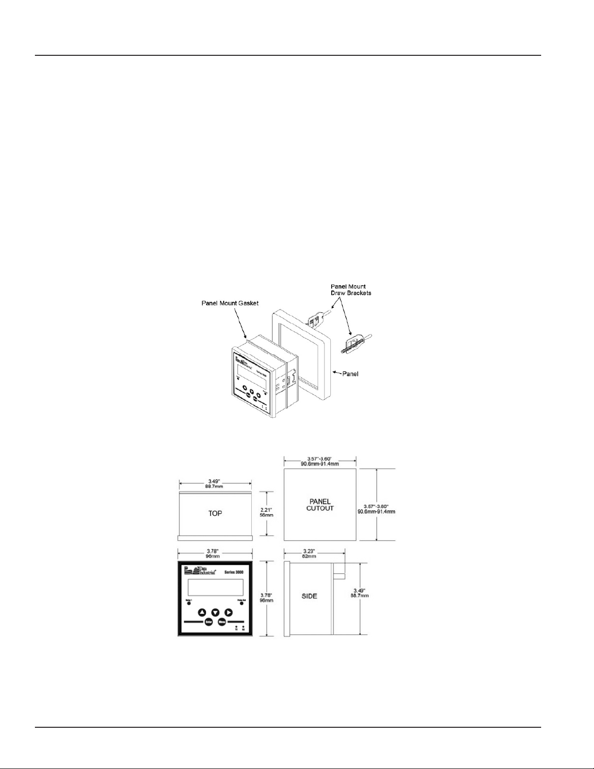
Panel Mount Installation
The Series 3050 panel mount is designed for through panel mounting, which allows access to the back of the unit. The Series
3050 Btu Monitor is secured to the panel by two draw brackets shown in Figure 1 below. Also refer to Figure 1 for monitor and
panel cutout dimensions.
6-11
Figure 1: Series 3050 Panel Mount and Mounting Dimensions
Page 7
Page 8
Series 3050 Btu Monitor
Figure 3 ( Power Supply Wiring)
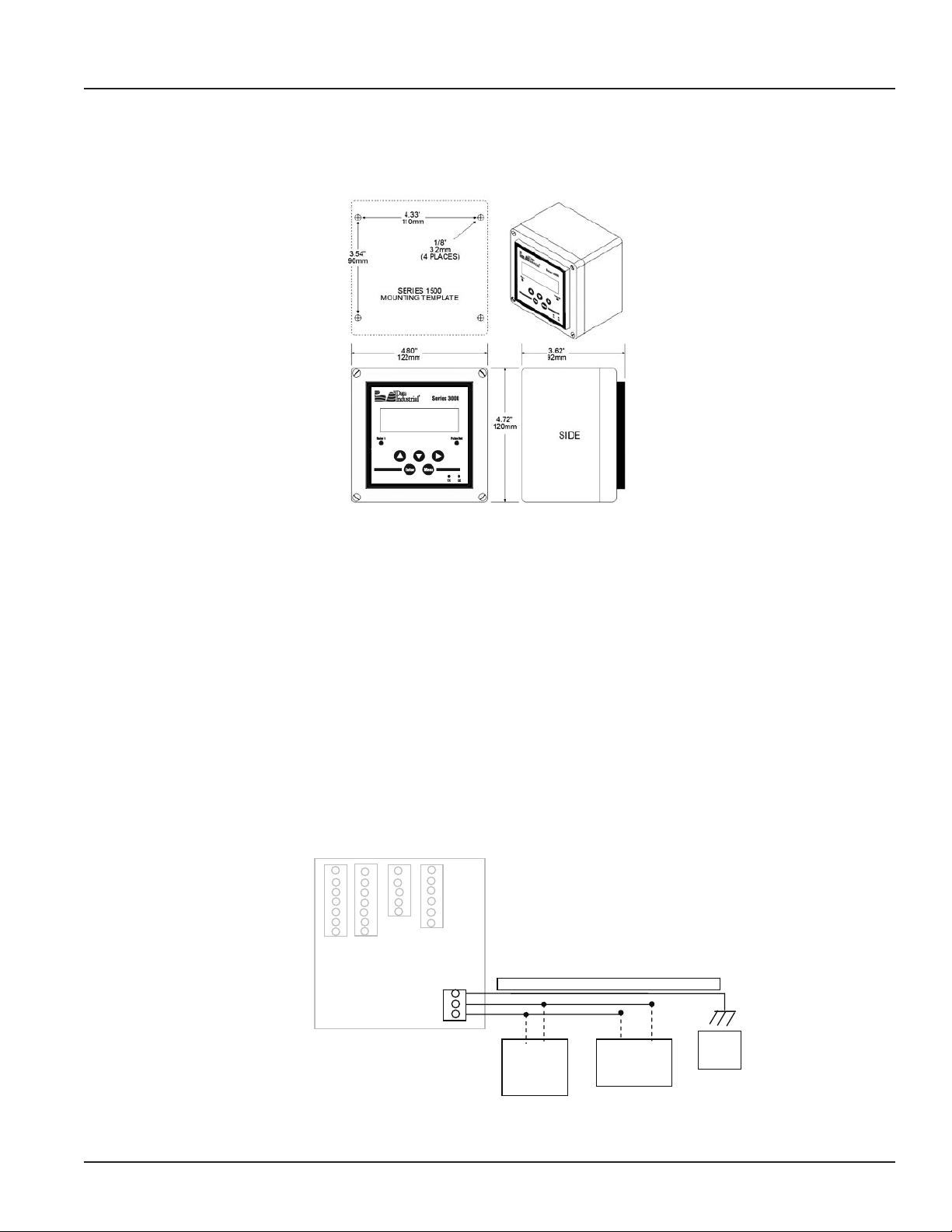
Wall Mount Installation
The Series 3050 wall mount is designed to mount onto a wall with four bolts or screws. The mounting hole pattern and box
dimensions for the Series 3050 NEMA4 waII mount are shown in Figure 2.
Figure 2: Wall Mount and Dimensions
Electrical Installation
Power Supply Wiring
The Series 3050 Btu Monitor requires 12-24 VDC/VAC to operate. Check the Specifications on page 29 for DC current draw
and AC Volt-Amp requirements.
A fused circuit is always recommended.
Connect the positive of the power supply to the Series 3050 terminal marked (ACL/DC+), and connect the negative of the
power supply to the Series 3050 terminal marked (ACC/DC-).
If a Badger Meter Data Industrial plug-in power supply (Model A1026, A-503) is being used, connect the black-white wire to
the terminal marked (ACL/DC+) and the black wire to the terminal marked (ACC/DC-).
Page 8
POWER
Earth 3
LV AC/DC(-) 2
LV AC/DC(+) 1
Ground wire should be heavy gauge and as short as possible
(+) (-)
12-24VDC
Power
Supply
Figure 3: Power Supply Wiring
OR
( Line) (Com)
12-24VAC
Power Supply
Earth
or
Panel
Ground
6-11
Page 9
Installation & Operation Manual
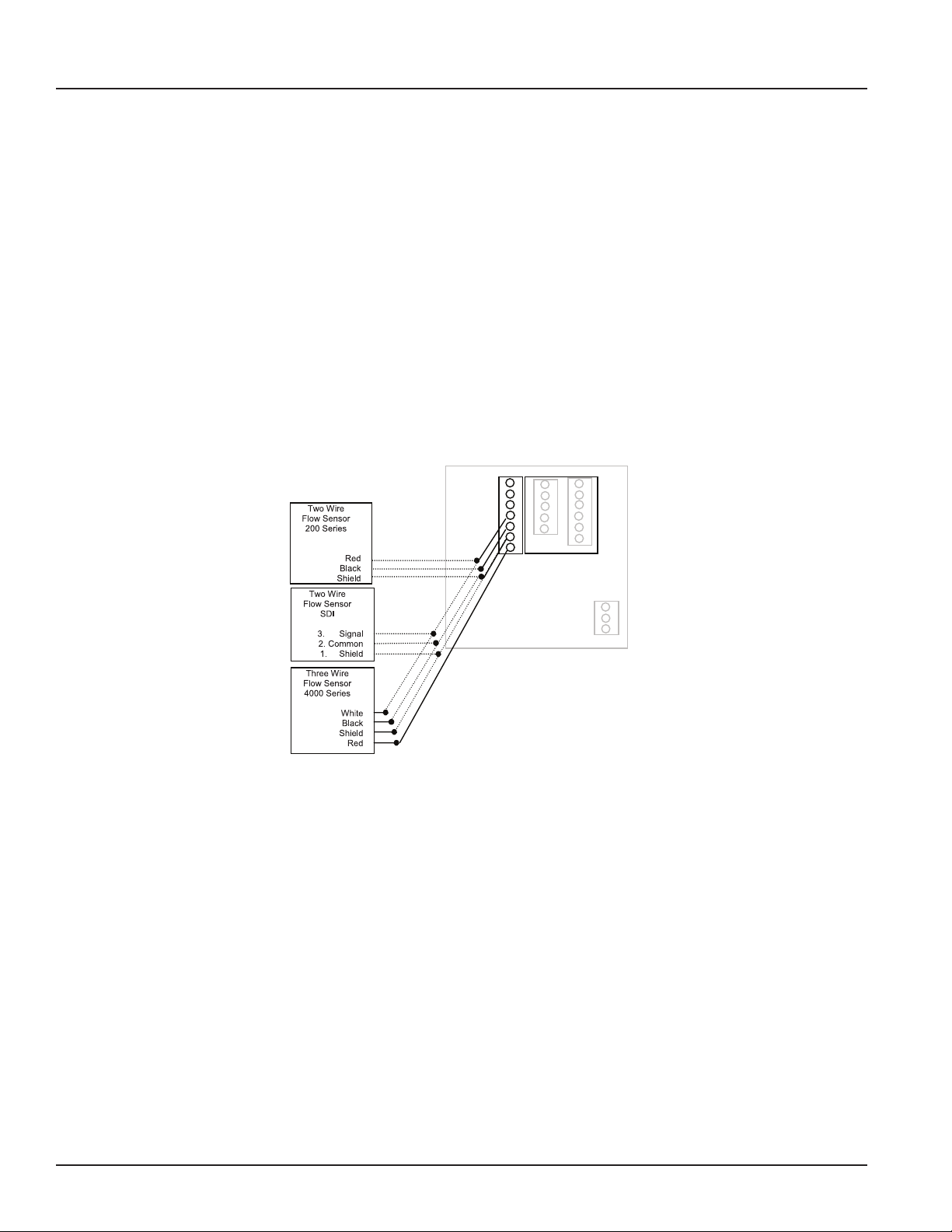
Flow Sensor Wiring
The Series 3050 flow sensor inputs are extremely versatile, designed to accept either two-wire or three-wire pulse inputs
(Data Industrial 200 Series, SDI or 4000 Series) or Analog inputs. Although different rear panel terminals are used, all
parameters are set with the LCD/keypad interface. There are no internal or external jumpers, switches or potentiometers to
move or adjust.
The following pulse input types are accommodated.
• Pulse-DI: Used for all Badger Meter Data Industrial Flow Sensors. Provides an internal pull-up resistor and uses “K”
and “Offset” values for calibration.
• Pulse–K Factor: Accepts non zero-crossing inputs but provides no internal pull-up, classical “K” ( pulses/gallon)
values for calibration.
• Pull-up-K Factor: Provides an internal pull-up resistor and uses classical “K” ( pulses/gallon) values for calibration.
NOTE: All the above pulse input types wire the same as shown in Figure 4. See the Programming Flow Chart on
page 18 for required input configuration.
1 ANALOG IN+
2 ANALOG IN3 SHIELD
4 SENSOR IN
5 GND
6 SHIELD
7 SENSOR PWR
6-11
Figure 4: Data Industrial Flow Sensor Wiring Examples (Two- and Three-Wire Pulse Types)
Page 9
Page 10
Series 3050 Btu Monitor
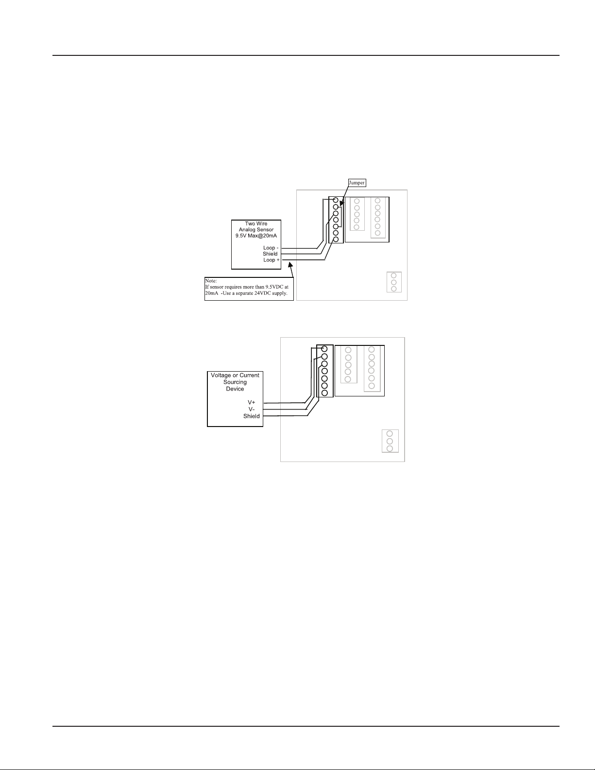
Analog Input
As an alternative to the pulse inputs, the Series 3050 can accept an Analog input. The input is non-isolated, but can accept
0-1VDC, 0-5VDC, 0-10VDC, 0-20mA and 4-20mA with both factory-defined and custom units of measure.
Low impedance 100 Ohm input for current inputs optimizes performance and flexibility or loop power supplies. Both the
low- and high-end scaling are independent and field configured by the installer.
NOTE: See the Programming Flow Chart on page 18 for required input configuration.
1 ANALOG IN+
2 ANALOG IN3 SHIELD
4 SENSOR IN
5 GND
6 SHIELD
7 SENSOR PWR
Figure 5: 4-20mA Analog Loop Powered Wiring
1 ANALOG IN+
2 ANALOG IN3 SHIELD
4 SENSOR IN
5 GND
6 SHIELD
7 SENSOR PWR
Figure 6: Voltage or Current Sourcing Analog Inputs
Page 10
6-11
Page 11

Installation & Operation Manual
Wiring Two Wire Thermistors and RTD’s
Wiring Two Wire Thermistors and RTD’s
Wiring Three Wire RTD’s
1 TEMP 1 IN +
2 TEMP 1 IN -
3 TEMP 1 GND
4 SHIELD
5 TEMP 2 GND
6 TEMP 2 IN -
7 TEMP 2 IN +
Jumpers
2 Wire
Thermistor
Located
in same
Supply
or
Return line
Flow Sensor
2 Wire
Thermistor
Temperature Input
The Series 3050 Btu Monitor can accept inputs from either a pair of thermistors or RTDs. The inputs are labeled T1 and T2.
Since the T1 sensor is used to convert the volumetric flow (Example: GPM) to the mass flow ( Example: Lbs/Hr) used in the Btu
calculations, the sensor connected to T1 should be in the same supply or return line as the Flow Sensor.
The temperature inputs of the Series 3050 are extremely versatile. In addition to the factory default two-wire10k @77°F Type
II Thermistors and three-wire 100 ohm Platinum RTDs, the unit can be programmed in the field for a wide variety of custom
RTDs and thermistors. Refer to the Programming Flow Chart. Contact the factory for assistance with any custom inputs.
2 Wire
Thermistor
Located
in same
Supply
or
Return line
Flow Sensor
3 Wire
RTD
T1
Located
in same
Supply
or
Return line
as
Flow Sensor
1 TEMP 1 IN +
2 TEMP 1 IN 3 TEMP 1 GND
Jumpers
2 Wire
Thermistor
4 SHIELD
5 TEMP 2 GND
6 TEMP 2 IN 7 TEMP 2 IN +
Figure 7: Wiring Two-Wire Thermistors and RTDs
Different Color Wire
Same Colored 2 Wires
3 Wire
RTD
1 TEMP 1 IN +
2 TEMP 1 IN 3 TEMP 1 GND
4 SHIELD
5 TEMP 2 GND
6 TEMP 2 IN 7 TEMP 2 IN +
Figure 8: Wiring Three -Wire RTDs
6-11
Page 11
Page 12
Series 3050 Btu Monitor
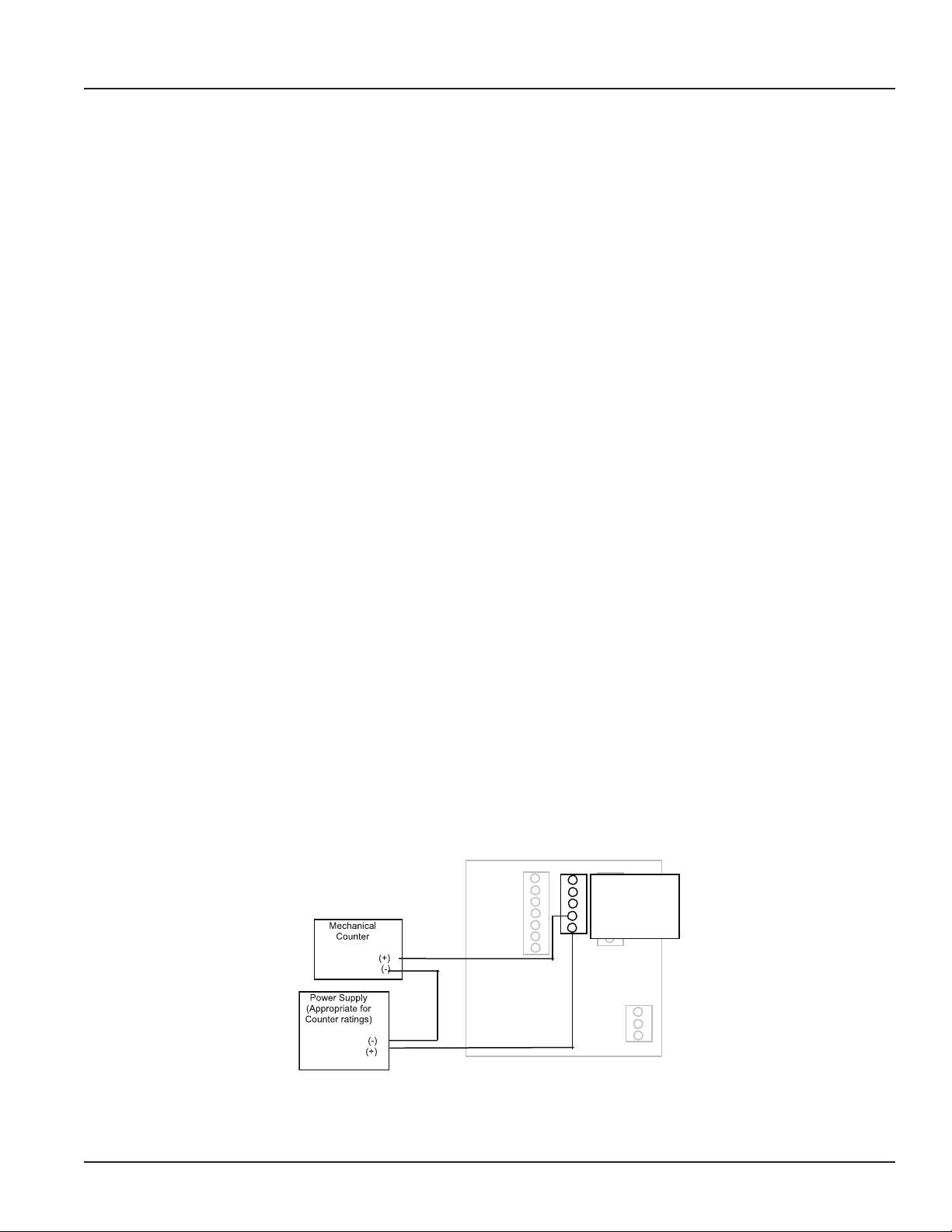
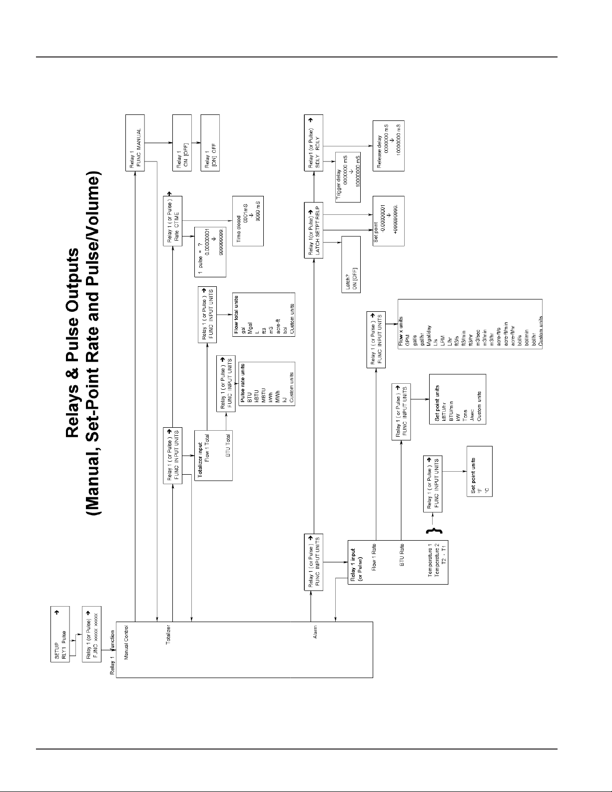
Solid State Switch and Form “C” Output Wiring
The Series 3050 Btu Monitor has one Normally Open (N.O.) solid state switch, and one solid state form “C” relay.
Check the Specifications on page 29 for maximum voltage and current ratings for each type output. These outputs are
completely independent, electrically isolated, and can be programmed as either Pulse or Set Point outputs.
When the “Totalizer” function is selected, the unit of measure and resolution are independent from the displayed units and
can be programmed where one pulse occurs once every 0000000.1 to 999999999. of units selected, with any pulse width
from 0001 to 9999mS.
When the “Alarm” is selected as the unit of measure and the resolution is independent from the displayed units, it allows the
unit to be programmed as either a high or low rate Set Point. Since the Set Point, Release Point and their associated time
delays are fully independent, this output can be either a classical high rate or low rate alarm, depending on the settings
selected. When design planning, keep in mind that although both of these outputs can be programmed as alarm points only,
the relay provides both N.O. and N.C. contacts. The switch is a simple N.O. contact.
Examples:
High Flow Set Point Control
The Set Point must be a value greater than the Release Point.
The relay output will have continuity between its N.C. terminal and “COM” until the flow has exceeded the Set Point (“SETPT”)
for a continuous period of time exceeding the Set Point Delay (“SDLY”), at which time the N.C. connection will open and the
N.O. contact will have continuity to the “COM” terminal. When the flow has dropped below the Release Point (“RELP") for a
continuous period of time exceeding the Release Point Delay (“RDLY”), the relay states will return to their original states. If the
latch has been set to “ON”, the relay will not release until manually reset once the Set Point and Set Delay have been satisfied.
Sources for the Set Point control can be Flow Rate, Energy Rate, T1, T2 or Delta T.
Low Flow Set Point Control
The Set Point must be a value less than the Release Point.
The relay output will have continuity between its N.C. terminal and “COM” until the flow drops below the Set Point (“SETPT”)
for a continuous period of time exceeding the Set Point Delay(“SDLY”), at which time the N.C. connection will open and the
N.O. contact will have continuity to the “COM” terminal. When the flow has again risen above the Release Point (“RELP”) for a
continuous period of time exceeding the Release Point Delay (“RDLY”), the relay states will return to their original states. If the
latch has been set to “ON”, the relay will not release until manually reset once the Set Point and Set Delay have been satisfied.
Sources for the Set Point control can be Flow Rate, Energy Rate, T1, T2 or Delta T.
1 RELAY 1 NO
2 RELAY 1 NC
3 RELAY 1 COM
4 PULSE 1 OUT
5 PULSE 2 OUT
Page 12
Figure 9: Relay and Switch Wiring Examples
6-11
Page 13
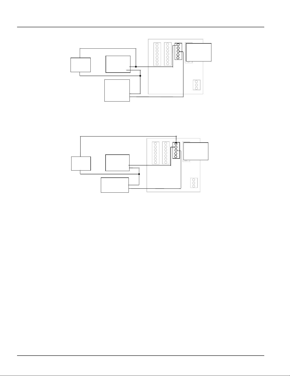
Figure 8
Relay and Switch Wiring Examples (continued)
( Chiller Control based on High Energy Usage with with indication
Chiller Motor
Figure 8
Relay and Switch Wiring Examples (continued)
( Chiller Control based on High Energy Usage with with indication
Figure 9
( Chiller Control based on Low Temperature Warning with indication
Chiller Motor
Starter
(1)
(2)
Power Supply
(Appropriate for
Motor Starter)
(COM)
(Line)
Indicator
Lamp
1 RELAY 1 NO
2 RELAY 1 NC
3 RELAY 1 COM
4 PULSE 1 OUT
5 PULSE 2 OUT
Indicator
Lamp
Starter
Power Supply
(Appropriate for
Motor Starter)
(COM)
(Line)
(1)
(2)
Figure 10: Relay and Switch Wiring Examples (continued)
Chiller Control Based on High Energy Usage with Indication
Chiller Relay
Indicator
Lamp
(1)
(2)
Installation & Operation Manual
1 RELAY 1 NO
2 RELAY 1 NC
3 RELAY 1 COM
4 PULSE 1 OUT
5 PULSE 2 OUT
1 RELAY 1 NO
2 RELAY 1 NC
3 RELAY 1 COM
4 PULSE 1 OUT
5 PULSE 2 OUT
Chiller Controller
(System Control Out)
Figure 11: Relay and Switch Wiring Examples (continued)
Chiller Control Based on Low Temperature Warning with Indication
(COM)
6-11
Page 13
Page 14

Series 3050 Btu Monitor
Figure 12
RS485 Communication
OUTPUT OPTION CARD
If the Series 3050 Btu Monitor was ordered with the Output Option card, it will have several additional outputs.
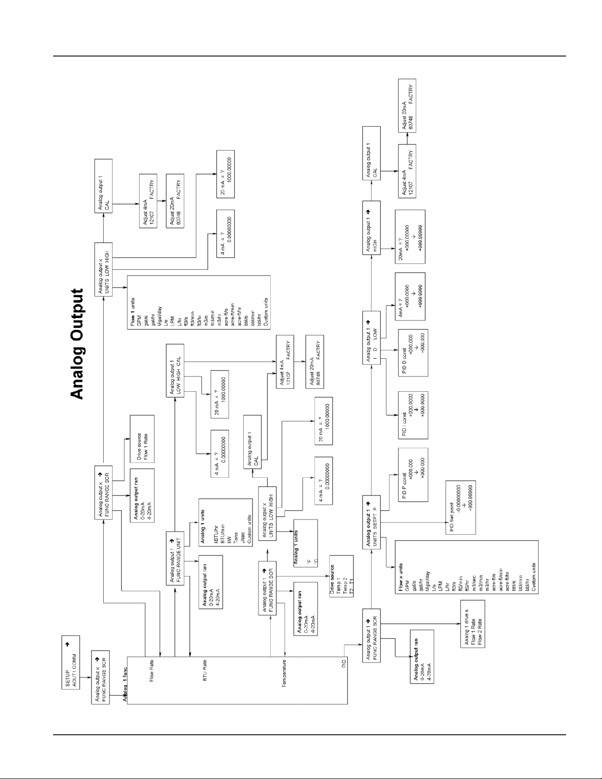
1. Analog Output ( 0-20mA; or 4-20mA ) which can be converted externally to 0-5VDC, 1-5VDC with a 250 Ohm resistor; or
0-10VDC or 2-10VDC with a500 Ohm resistor. A 15VDC power supply is provided to permit current sinking or sourcing. The
Series 3050 has special software that permits the Analog output.
2. USB for direct access to a computer using a standard mini-USB cable.
3. RS-485 for fully addressable Modbus or BACnet communication.
1 RS485 B
2 RS485 A
3 RS485 GND
4 LOOP +
5 LOOP 6 GND
Figure 12: Current Sourcing Analog Output
1 RS485 B
2 RS485 A
3 RS485 GND
4 LOOP +
5 LOOP 6 GND
Figure 13: Current Sinking Analog Output
1 RS485 B
2 RS485 A
3 RS485 GND
4 LOOP +
5 LOOP 6 GND
Shield
RS485 -
RS485 +
Model 3700
Model 345WT
or other
MODBUS
Master
Device
Page 14
Figure 14: RS485 Communication (Modbus and BACnet)
6-11
Page 15

Modbus points
Figure 12
RS485 Communication
Figure 13
Model 3700
Model 345WT
or other
MODBUS
Master
Device
Shield
RS485 -
RS485 +
1 RS485 B
2 RS485 A
3 RS485 GND
4 LOOP +
5 LOOP -
6 GND
All of the following are available as Input Registers.
Addr Function
1. Flow 1 Rate (GPM)
2. Flow 2 Rate
3. Flow 1 Total (gallons)
4. Flow 2 Total
5. BTU Rate (kBTU/hr)
6. BTU Total (kBTU)
7. Batch 1 Count
8. Batch 2 Count
9. Temp 1 (deg F)
10. Temp 2
Installation & Operation Manual
11. Temp Delta (T2-T1)
USB Port
1 RS485 B
2 RS485 A
3 RS485 GND
4 LOOP +
5 LOOP 6 GND
NOTE: To communicate using the USB port requires Windows HyperTerminal or other similar communications
software. This port is part of the Analog Output Option card. See the USB Communications section of
PROGRAMMING on page 16 for instructions on how to use this port.
Use
Standard Cable
USB Type A Male
To
Type Mini B 5 Pin Male
Connect to
Computer USB
Com Port
Figure 15: USB Analog Output
6-11
Page 15
Page 16
Series 3050 Btu Monitor
DISPLAY AND KEY PAD
The Series 3050 Btu Monitor has a two line by 16-character display with two modes of operation and 5 keys on the front panel
for programming. Two of the keys( Menu and Enter) serve a single function while the three remaining keys () serve dual
purposes.
When the Series 3050 is first powered up, it runs through internal self checks while displaying “Badger Meter DIC
Initializing." At the end of this cycle its normal mode display will appear.
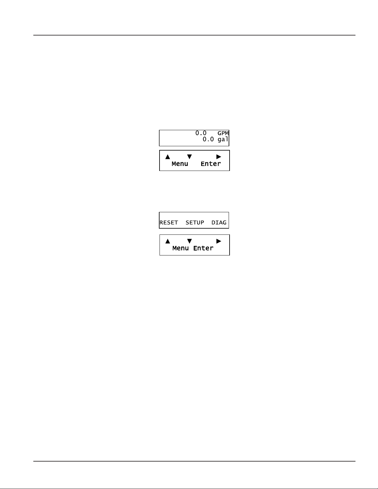
In the normal mode, if still using the factory defaults, Flow Rate will be displayed on the top line, and Flow Total displayed on
the bottom. Both lines can be custom-defined in the field as desired. In the normal mode the Enter key has no function.
Figure 16: Normal Mode Display
The other mode is the program mode, used to configure the unit. Enter and exit this mode by pressing the Menu key. See the
programming flow chart.
Figure 17: Program Mode Display
Page 16
6-11
Page 17
Installation & Operation Manual
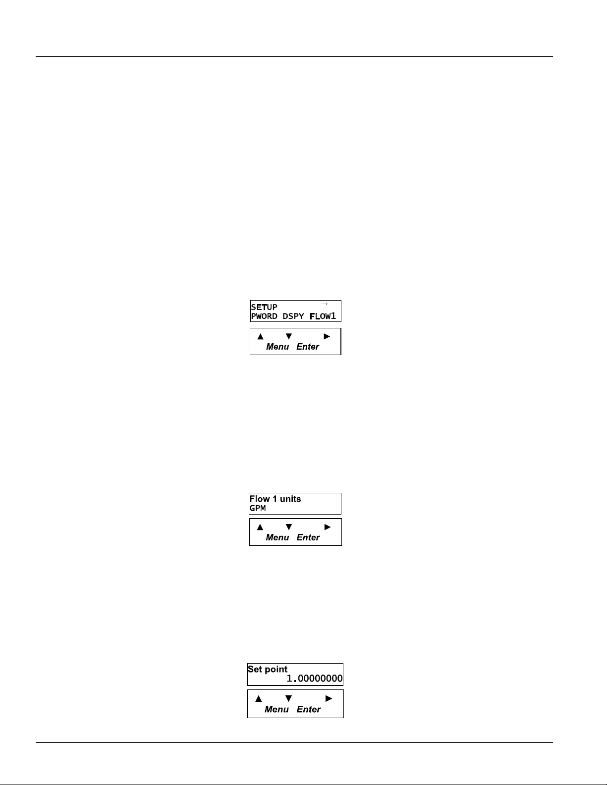
PROGRAMMING
With the normal mode display showing, pressing the Menu key will enter the programming mode. In this mode, the three
arrow keys () are used on the selection screens to select the option displayed above the key, and on the option list
screens to scroll up or down a list of choices, like a pull-down menu. It should be noted that most screens presenting choices
show three choices, one for each arrow key. When the number of choices exceeds three, a small arrow () appears on the
upper right side of the display indicating there are more choices on that level. Pressing Enter toggles to the next set of
choices. Once the selection has been made, the Enter key also is used to complete the selection. Pressing the Menu key
returns back to the normal mode display.
Selection Screens
Most selection screens show three choices, one for each arrow () key. When the number of choices exceeds three, a
small arrow ( ) appears on the upper right side of the display indicating there are more choices on that level. Press Enter to
view the next set of choices.
For example, pressing Menu from the normal mode screen shows the “RESET SETUP DIAG” screen. Pressing the key brings
up the reset screens. The key brings up the setup screens and the key brings up the diagnostic screens. If thekey is
pressed, the screen would appear as follows.
Figure 18: Selection Screen
Option List Screens
Units of measure is an example of an options list screen.
Pressing the key scrolls up the list while the key scrolls down through the list. In this case starting with GPM; gal/s; gal/
hr;…LPM;….ending in a selection of custom units.
Pressing Enter completes the selection. Pressing Menu leaves the selection unchanged. The key has no function on this
type of screen.
Figure 19: Options List Screen
Data Screens
Some screens are data entry screens. For example, Set Points or Custom Units screens.
When a data entry screen is first displayed, the current value will be displayed. The cursor will be flashing the most left hand
digit. Pressing the key will increase the value. The key will reduce it. If the cursor is flashing the decimal point pressing
thekey will move the decimal point to the right, pressing the key will move the decimal to the left.
6-11
Figure 20: Data Entry Screen
Page 17
Page 18

Series 3050 Btu Monitor
Page 13
Programming Flow Chart
Page 18
6-11
Page 19

Installation & Operation Manual
6-11
Page 19
Page 20

Series 3050 Btu Monitor
Page 15
Page 20
6-11
Page 21
Installation & Operation Manual
Page 16
6-11
Page 21
Page 22
Series 3050 Btu Monitor
Page 17
Page 22
6-11
Page 23

Installation & Operation Manual
6-11
Page 23
Page 24
Series 3050 Btu Monitor
USB Communication
If the Data Industrial Series 3050 Btu Monitor is ordered with an Analog Output Option card, a five-pin USB connector is also
included. As much as possible the commands mimic the use of the Front Panel controls.
To use this feature the following are required.
1. PC with USB ports and Windows HyperTerminal or other communications software
2. FTDI Virtual COM port drivers http://www.ftdichip.com/FTDrivers.htm
3. USB 2.0 A to Mini-B 5-pin cable
To communicate using HyperTerminal, use the following procedure.
1. Make sure that the Series 3050 has a Mini-B ve-pin connector on the back panel. (The Series 3050 must have an Analog
Output Option card installed and will be marked Series # 3050-1x.)
2. Be sure that the appropriate FTDI Virtual COM port drivers are installed on you computer.
3. Plug the USB 2.0 A end of the cable into an available USB port on your computer. Plug the Mini-B five-pin end into the
back of the Series 3050.
Page 24
6-11
Page 25
Installation & Operation Manual
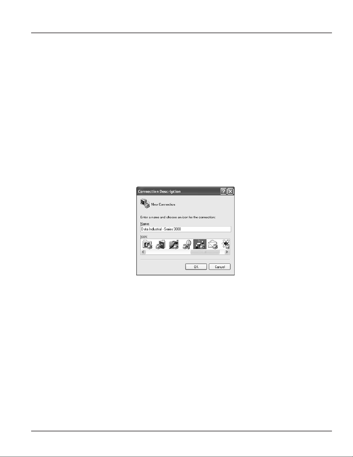
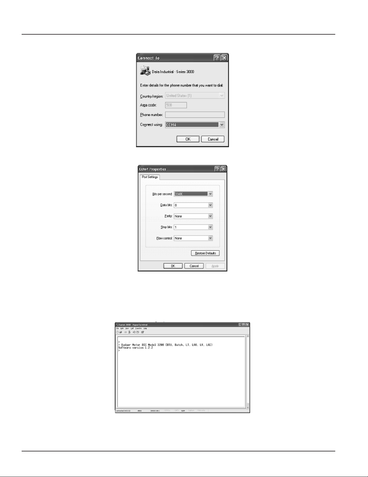
4. Run HyperTerminal (from the Windows Start Menu) and create a new connection with a name and icon.
5. Congure this Port with 38400 baud, 8 data bits, 1 stop bit, no parity and no ow control.
6. When connected, a ">" symbol will appear in the upper left corner of the main HyperTerminal display screen. Press the
“Enter Key.” Both the Rx and Tx LEDs on the front of the Series 3050 should ash once, and the “Badger Meter DIC …
Software Version…” text message should appear.
The Series 3050 Btu Monitor is now communicating, ready to take commands from the list below.
6-11
Page 25
Page 26

Series 3050 Btu Monitor
USB COMMAND LIST
In the list below, brackets indicate an argument, specifying
its type and value range. For instance [0-18] stands for any
number between 0 and 18 (inclusive).
Example: “display line1 = 1” sets Line 1 of the display to display
#1, which happens to be the totalizer for flow channel 1.
Diagnostics:
id – show model number & software version
echo [on/o] – turn on/o interactive command line:
with echo o, this interface is more
amenable to scripting; it still accepts the
same commands.
Any command entered without an “ = “ sign and
variable will display the current setting.
Example: Typing “display line1” returns “0” which is the
variable for Flow rate.
read ow [1-2] – read the current ow on channel 1 or 2
in GPM.
read ow [1-2] total – read the current total ow on
channel 1 or 2 in gallons.
DISPLAY CONFIGURATION
display line1 = [0-18] – set line 1 of the display
display line2 = [0-18] – set line 2 of the display
valid options are:
0: ow 1 rate
1: ow 1 total
2: ow 2 rate
3: ow 2 total
4: ow 1+2 rate
5: ow 1+2 total
6: ow 1-2 rate
7: ow 1-2 total
8: ow 2-1 rate
9: ow 2-1 total
14: BTU rate
15: BTU total
16: temperature 1&2
17: temperature 1-2
display urate = [0.1-10] – set the update rate of the display, in
seconds
FLOW INPUT CHANNEL CONFIGURATION
ow [1-2] sensor type = [0-4] – ow sensor type:
0: PulseDI,
1: PulseKFactor,
2: PullupKFactor
3: Analog
ow [1-2] sensor dical k = [x] – DI-type ow sensor k
ow [1-2] sensor dical o = [x] – DI-type ow sensor oset
ow [1-2] sensor kfact = [x] – K factor for non-DI sensors
ow [1-2] sensor analog units = [0-19] – ow units for analog
input
ow [1-2] sensor analog range = [0-4] – current range for
analog input
ow [1-2] sensor analog high = [x] – ow rate @max current
ow [1-2] sensor analog low = [x] – ow rate @min current
ow [1-2] sensor avg = [0-100] – averaging "time constant," in
seconds:
ow [1-2] rate units = [0-19] – ow (channel) rate units to
display.
0: GPM
1: gal/s
2: gal/hr
3: Mgal/day
4: L/s
5: LPM
6: L/hr
7: ft3/s
8: ft3/min
9: ft3/hr
10: m3/s
11: m3/min
12: m3/hr
13: acreft/s
14: acreft/min
15: acreft/hr
16: bbl/s
17: bbl/min
18: bbl/hr
19: Custom
ow [1-2] rate ndigits = [2-10] – number of decimal places to
show for ow rate
ow [1-2] rate custom label = [string] – set the label for custom
units
ow [1-2] rate custom conv = [0-100] – conversion factor for
custom units
ow [1-2] total units = [0-7] – set the totalizer units to display
0: gal
1: Mgal
2: L
3: ft3
4: m3
5: acreft
6: bbl
7: Custom
Page 26
6-11
Page 27

Installation & Operation Manual
BTU CONFIGURATION
Btu rate units = [0-5] – set the Btu rate units:
0: kBtu/hr
1: Btu/min
2: kW
3: TR
4: J/s
5: Custom
Btu rate ndigits = [2-10] – number of decimal digits to display
Btu rate custom label = [string] – Btu rate custom unit label
Btu rate custom conv = [0-100] – custom unit conversion
factor
Btu total units = [0-6] – Btu totalizer units:
0: BTU
1: kBTU
2: MBTU
3: kWh
4: MWh
5: kJ
6: Custom
Btu total ndigits = [2-10] – number of decimal digits to
display
Btu total custom label = [string] – Btu totalizer custom
unit label
Btu total custom conv = [0-100] – custom unit
conversion factor
Btu total mode = [0-2] – totalizer mode:
0: Heating
1: Cooling
2: Heating & Cooling
Btu sensor type = [0-4] – temperature sensor type:
0: DI Thermistor
1: DI RTD
2: Custom Thermistor
3: Custom RTD
4: No sensor
Btu sensor correct_k = [0-10] – correction factor
Btu sensor temp_unit = [0-1] – temperature units to
display
0: deg F
1: deg C
Btu sensor t2adj = [-10-10] – t2a
RELAY OUTPUT CONFIGURATION
relay [1-5] func = [0-9] – relay function; relay 5 is the pulse
output
0: Totalizer
1: Alarm
2: Manual Control
relay [1-5] input = [0-8] – relay input; depends on source
for totalizer:
0: Flow 1 Total
for alarms:
0: Flow 1 Rate
relay [1-5] units = [0-19] – units on setpoints/rates; depends on
src/input
ow units: same as 'ow [1-2] rate units' above
volume units: same as 'ow [1-2] total units'
relay [1-5] manual = [on/o] – manually set relay on or o, if in
manual mode
relay [1-5] rate = [x] – totalizer rate
relay [1-5] ctime = [0-10000] – pulse width in milliseconds
relay [1-4] latch = [on/o] – turn on/o relay latching
relay [1-4] setpoint = [x]
relay [1-4] releasepoint = [x]
ANALOG OUTPUT CONFIGURATION
analogout [1-2] func = [0-3]
0: Flow rate
1: BTU rate
2: Temperature
3: PID control
analogout [1-2] src = [0-4]
for ow rate:
0: Flow 1 rate
1: Flow 2 rate
2: Flow sum
3: Flow 1-2
4: Flow 2-1
for Btu rate: not used
for temperature:
0: Flow rate
1: Temp 2
2: Temp Delta
for PID control:
0: Flow 1 rate
1: Flow 2 rate
analogout [1-2] range – [0-1]
0: 0-20mA
1: 4-20mA
analogout [1-2] low = [x] – value corresponding to 0 (or 4) mA
analogout [1-2] high = [x] – value corresponding to 20mA
analogout [1-2] setpoint = [x] – PID setpoint
analogout [1-2] P = [x] – PID constants
analogout [1-2] I = [x] – PID constants
analogout [1-2] D = [x] – PID constants
6-11
Page 27
Page 28

Series 3050 Btu Monitor
RS485 COMM PORT CONFIGURATION
comm baudrate = [0-7]
0: Auto
1: 300
2: 1200
3: 2400
4: 9600
5: 19200
6: 38400
7: 76800
comm mstpaddr = [0-127] – BACnet/MSTP address
comm maxmaster = [0-127] – BACnet/MSTP max master
address
comm devinst = [x] – BACnet device instance ID
comm mbslaveaddr = [0-255] – Modbus slave address
MODBUS
Addr Function
1 Flow 1 rate (GPM)
2 Flow 2 rate
3 Flow 1 Total (gallons)
4 Flow 2 Total
5 BTU Rate (kBTU/hr)
6 BTU Total (kBTU)
7 Batch 1 Count
8 Batch 2 Count
9 Temp 1 (deg F)
10 Temp 2
11 Temp Delta (T2-T1)
TROUBLESHOOTING
Trouble Codes:
1 Relay 1 totalizer rate exceeded
2 Relay 2 rate exceeded
3 Relay 3 rate exceeded
4 Relay 4 rate exceeded
5 Pulse out rate exceeded
20 Error reading EEPROM on faceplate
21 Error writing EEPROM
22 Analog Input card missing
24 Temperature Input card missing
25 Invalid ow units congured
26 Invalid volume units congured
27 Bad input frequency
29 Internal error calculating ow rate
31 Error reading from analog input AD converter
channel 1
32 Error reading from analog input AD converter
channel 2
36 Error writing to analog input AD converter channel 1
37 Error writing to analog input AD converter channel 2
50 Error reading I2C address 0 (relays, buttons, and LEDs)
51 Error writing to I2C address 0
52 Error reading I2C address 1 (analog input card control lines)
53 Error writing I2C address 1
54 Error reading I2C address 2 (temperature input card control lines)
55 Error writing I2C address 2
71 Watchdog timer reset occurred
82 Fatal error initializing EEPROM
Page 28
6-11
Page 29

Installation & Operation Manual
FLOW SENSOR INPUTS
Type Threshold Signal Limit Frequency Pull-up Impedance Aux. Power Calibration
Pulse-Di 2.5 VDC 30VDC 0.4 Hz to
1K to12VDC — 12VDC@30mA K + Offset
10kHz
Pulse-K Factor 2.5 VDC 30VDC 0.4 Hz to
— — 12VDC@30mA Pulse/Gal
10kHz
Pull-up-K Factor 2.5 VDC 30VDC 0.4 Hz to
1K to12VDC — 12VDC@30mA Pulse/Gal
10kHz
Analog – 4-20mA — 50mA Fused — — 100 Ω 12VDC@30mA Pulse/Gal
Analog – 0-20mA — 50mA Fused — — 100 Ω 12VDC@30mA Linear
Analog – 0-1 VDC — 30VDC — — 100 Ω 12VDC@30mA Linear
Analog – 0-5 VDC — 30VDC — — 100 Ω 12VDC@30mA Linear
Analog – 0-10 VDC — 30VDC — — 100 Ω 12VDC@30mA Linear
Rate Units of Measure: GPM; gal/sec; gal/hr; Mgal/day; LPS; LPM; LPH; ft3/Sec; ft3/min; ft3/hr;m3/sec; m3/min; m3/hr; acre-ft/sec; acre-ft/min; acre-ft/hr; bbl/sec; bbl/min; bbl/hr;
and field programmed custom units 0.00 to 999999999
Total Units: gallons; Mgal; liters; ft3; m3; acre-ft; bbl; and field programmed custom units 0.00 to 999999999
SPECIFICATIONS
Voltage
12-24 VDC / VAC
(Limit: 8-35VDC)
(Limit: 8-28VAC)
DC current draw (~280mA)
AC power rating (~5 VA)
Display
16 character by two-line alphanumeric
dot matrix 7.95mm high backlit LCD
Operating Temperature
-20°C to +70°C
Storage Temperature
-30°C to +80°C
Dimensions
Panel Mount:
3.78"W x 3.78"H x 3.23"D
(96mm x 96mm x 63mm)
Wall Mount:
4.80"W x 4.72"H x 3.63"D
(120mm x 120mm x 92mm)
Weight:
panel mount 12 oz
Series
Option - Analog Output, RS485 (BACnet / Modbus), and USB
Option - Mounting
Pulse and Relays
Both pulse and relay are fully functional as either
totalizing, or Set Point outputs.
Pulse Electrical
1 Amp @ 35VDC/ 30VAC
Closed: 0.5Ω @ 1 AMP Open: >108Ω
Relay Electrical
Resistive load: 5Amp@120VAC/30VDC
Inductive load: 1Amp@120VAC/30VDC
Pulse/Unit Volume (Totalizer)
Driving Source: ow total; Btu total
Units: any predened or custom unit
Rate: 1 Pulse per 1.0000000 to 99999999 units
Contact Time: 1 to 9999 mS
Set Point (Alarm)
Driving Source: ow rate; Btu rate;
temperature 1; temperature 2, delta T
Units: Any predened or custom unit
Set Point : 1.0000000 to 999999999
Delay to Set: 1 to 9999 Seconds
Release Point: 1.0000000 to 999999999
Delay to Release: 1 to 9999 seconds
BTU 3050
No Option 0
Analog Output, RS485 with BACnet and Modbus, and USB 1
Panel Mount 0
Wall Mount 1
Example: 3050 - x x
Optional Analog Output
Driving Source: ow rate; PID control
Range: 4-20mA; 0-20mA (isolated current sinking
or sourcing)
Sinking: 30VDC @ 0mA maximum; 3 volts
@20mA minimum
Sourcing: 600 W maximum load
USB Communication
Provides complete access to all programming and
operation features.
Requirements:
USB 2.0 A to Mini-B 5-Pin Cable
(Example: SYSONIC model UAM56 GWT/B)
RS-485 Communication
Supports: Modbus and BACnet/MSTP
Accessories
Programming kit
Wall mount kit
6-11
Figure 21: Series 3050 Ordering Matrix
Page 29
Page 30

Series 3050 Btu Monitor
Intentionally blank page
Page 30
6-11
Page 31

Intentionally blank page
Installation & Operation Manual
6-11
Page 31
Page 32

Please see our website at www.badgermeter.com
for specic contacts.
Data Industrial is a registered trademark of Badger Meter, Inc.
Other trademarks appearing in this document are the property of their respective entities.
Copyright 2011, Badger Meter, Inc. All rights reserved.
Due to continuous research, product improvements and enhancements,
Badger Meter reserves the right to change product or system specications
without notice, except to the extent an outstanding contractual obligation exists.
Badger Meter | P.O. Box 245036, Milwaukee, Wisconsin 53224-9536
800-876-3837 | infocentral@badgermeter.com | www.badgermeter.com
 Loading...