

Page 1
Badger
Series 200
The Badger Meter Series 200 fl ow sensors feature a six bladed
impeller design with a proprietary non-magnetic sensing
mechanism. The forward swept impeller shape provides higher,
more consistent torque and is less prone to be fouled by water
borne debris. The forward curved shape coupled with the
absence of magnetic drag provides improved operation and
repeatability even at lower fl ow rates. This is especially true
where the impeller is exposed to metallic or rust particles found
in steel or iron pipes. As the liquid fl ow turns the impeller, a low
impedance square wave signal is transmitted with a frequency
proportional to the fl ow rate. The signal can travel up to 2000
feet between the fl ow sensor and the display unit without the
need for amplifi cation. All sensors except irrigation versions are
supplied with 20 feet of 2-conductor 20 A WG shielded U.L. type
PTLC 105°C cable.
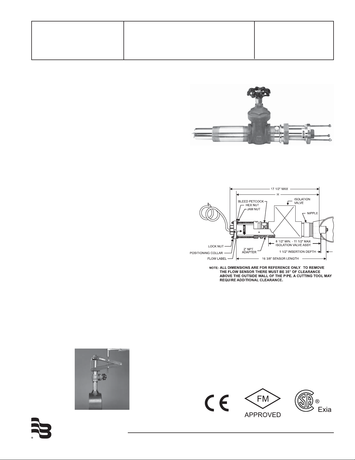
MODEL 225BR AND 226BR/226SS SENSORS
The Model 225BR and 226BR/226SS sensors are used for fl ow
measuring applications in most metallic or non-metallic pipes
where it would be diffi cult to shut down or drain the line for
installation or service. The Model 225 features a gate valve for
isolation. The Model 226 uses a ball valve. If the pipe is to be
hot tapped, the ball valve is recommended. The sensor mounts
in a 2” NPT pipe saddle or Threadolet® for installation in pipe
sizes from 3” to over 40”. Positioning nuts on the three threaded
retaining rods allow the sensor to be accurately positioned to
a standard insertion depth of 1½” into the pipe. When this
insertion depth is maintained, and there are at least 10 upstream
and 5 downstream diameters of straight uninterrupted fl ow, an
accuracy of +/-1% of full scale can be obtained between fl ow
velocities of 0.5 to 30 feet/second. Each sensor is equipped
with an isolation valve and pipe nipple to allow the sensor to
be installed in a pressurized pipe. This is accomplished by fi rst
attaching a saddle or Threadolet® to the pipe and screwing the
nipple and isolation valve into the saddle or Threadolet fi tting. A
hole is then drilled through the pipe using a commercial tapping
machine. When completed, the tapping apparatus is removed,
the isolation valve is closed, and the sensor is installed using a
Model HTT Hot Tap Tool.
®
Models 225/226
Hot Tap Flow Sensor
Technical
Brief
Dimensions Models 225/226
NOTE: that the overall length of the sensor tube is 18 inches
(457mm), however, a clearance height of 35 inches (127mm)
should be allowed for the fully extended length of the sensor
tube outside the isolation valve.
Model HTT - Hot Tap Tool
BadgerMeter, Inc.
DTB-011-01
4-09
Page 2
SPECIFICATIONS
SIZE
ELECTRONICS HOUSING
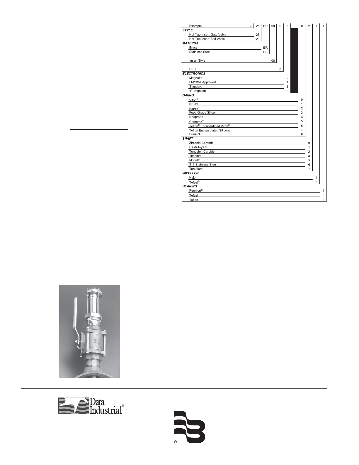
Series 200 Hot Tap Matrix (sizes 3” and up)
Wetted Materials for all sensors
–(see ordering matrix)
Sensor Sleeve and Hex Adapter for 225BR and 226BR
– Sleeve: Admiralty Brass, UNS C44300
– Hex Adapter: Valve Bronze, UNS C83600
Sensor Sleeve and Hex Adapter for 226SS
– 316 Series Stainless Steel
Temperature Ratings
– Standard Version:
221°F (105°C) continuous service
– Irrigation Electronics
150°F (66°C)
Pressure Ratings
At 100°F
225BR 300 psi
226BR 400 psi
226SS 400 psi
Recommended Design Flow Range
– 0.5 to 30 ft/sec
– Initial detection below 0.3 ft/sec
Accuracy
– ± 1.0% of full scale over recommended design fl ow range
– ± 4.0% of reading within calibration range
Repeatability
– ± 0.3% of full scale over recommended design fl ow range
Linearity
– ± 0.2% of full scale over recommended design fl ow range
Transducer Excitation
– Quiescent current 600uA@8VDC to 35VDC max.
– Quiescent voltage (V
Supply Voltage -(600uA*Supply impedance)
– ON State (V
Max. 1.2VDC@40mA current limit (15W+0.7VDC)
Low
Output Frequency
– 3.2 Hz to 200 Hz
Output Pulse Width
)
high
)
– 5 msec ±25%
Electrical Cable for Standard Sensor Electronics
– 20 feet of 2-conductor 20 AWG shielded U.L. type PTLC wire
provided for connection to display or analog transmitter unit.
Rated to 105°C. May be extended to a maximum of 2000 feet
with similar cable and insulation appropriate for application.
Electrical Cable for IR Sensor Electronics
– 48 inches of U.L. Style 116666 copper solid AWG 18 wire with
direct burial insulation. Rated to 105°C.
Badger® and Data Industrial® is a registered trademark of Badger
Meter, Inc.
Pennlon® is a registered trademark of the Dixon Corporation.
Hastalloy ® is a registered trademark of The Haynes Stellite Company.
Monel® is a registered trademark of Inco Alloys International, Inc.
Tefl on®, Tefzel® and Viton® are registered trademarks of DePont Dow
Elastomers.
Chemraz® is a registered trademark of Green Tweed.
226SS
Threadolet® is a registered trademark of Bonney Forge & Tool Works
Coorporation.
Due to continuous research, product improvements and enhancements, Badger
Meter reserves the right to change product or system specifications without notice,
except to the extent an outstanding contractual obligation exists.
Please see our website at www.badgermeter.com
for specific contacts.
Copyright © Badger Meter, Inc. 2009. All rights reserved.
BadgerMeter, Inc.
P.O. Box 581390, Tulsa, Oklahoma 74158
(918) 836-8411 / Fax: (918) 832-9962
www.badgermeter.com
 Loading...