

Page 1
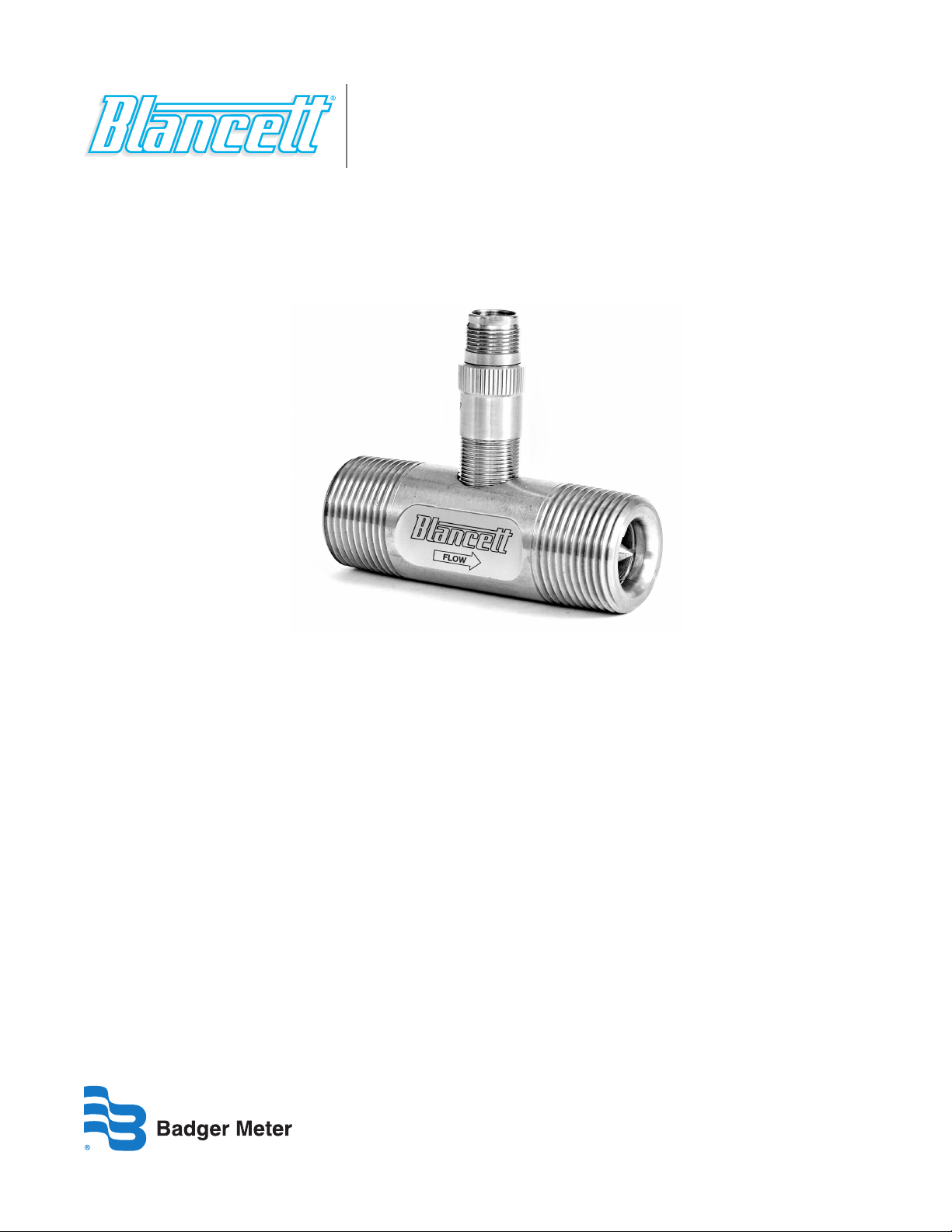
Turbine Flow Meter
Model 1200 Flow Meter
TUR-UM-00290-EN-01 (November 2013)
User Manual
Page 2

Turbine Flow Meter, Model 1200 Turbine Flow Meter
Page ii November 2013
Page 3

User Manual
CONTENTS
INTRODUCTION . . . . . . . . . . . . . . . . . . . . . . . . . . . . . . . . . . . . . . . . . . . . . . . . . . . . . . . . . . . . . . . . . . . . . . 5
OPERATING PRINCIPLE . . . . . . . . . . . . . . . . . . . . . . . . . . . . . . . . . . . . . . . . . . . . . . . . . . . . . . . . . . . . . . . . . . 5
SPECIFICATIONS . . . . . . . . . . . . . . . . . . . . . . . . . . . . . . . . . . . . . . . . . . . . . . . . . . . . . . . . . . . . . . . . . . . . . . 6
INSTALLATION . . . . . . . . . . . . . . . . . . . . . . . . . . . . . . . . . . . . . . . . . . . . . . . . . . . . . . . . . . . . . . . . . . . . . . . 7
WIRING DIAGRAM . . . . . . . . . . . . . . . . . . . . . . . . . . . . . . . . . . . . . . . . . . . . . . . . . . . . . . . . . . . . . . . . . . . . . 9
OPERATIONAL STARTUP . . . . . . . . . . . . . . . . . . . . . . . . . . . . . . . . . . . . . . . . . . . . . . . . . . . . . . . . . . . . . . . . 10
PART NUMBER INFORMATION . . . . . . . . . . . . . . . . . . . . . . . . . . . . . . . . . . . . . . . . . . . . . . . . . . . . . . . . . . . . 10
TROUBLESHOOTING GUIDE . . . . . . . . . . . . . . . . . . . . . . . . . . . . . . . . . . . . . . . . . . . . . . . . . . . . . . . . . . . . . . 11
Page iii November 2013
Page 4

Turbine Flow Meter, Model 1200 Turbine Flow Meter
Page iv November 2013
Page 5

Turbine Rotor
Magnetic Pickup
Signal
User Manual
INTRODUCTION
The Blancett Model 1200 in-line turbine flow meter was engineered for applications in high corrosive environments.
Developed for use in petrochemical and other process industries with liquid chemical flows, the Model 1200 turbine provides
accuracy and durability in aggressive industrial environments. The meter features a 303 stainless steel body and internal
wetted parts, with two type 440 stainless steel ball bearings.
OPERATING PRINCIPLE
Fluid entering the meter passes through the inlet flow straightener, which reduces its turbulent flow pattern and improves
the fluid’s velocity profile. Fluid then passes through the turbine, causing it to rotate at a speed proportional to the fluid
velocity. As each turbine blade passes through the magnetic field, the blade generates an AC voltage pulse in the pickup coil
at the base of the magnetic pickup (see Figure 1). These pulses produce an output frequency proportional to the volumetric
flow through the meter. The output frequency represents flow rate and/or totalization of fluid passing through the turbine
flow meter.
or
Other Frequency
Output Device
Output
Figure 1: Schematic illustration of electric signal generated by rotor movement
Page 5 November 2013
Page 6

Turbine Flow Meter, Model 1200 Turbine Flow Meter
SPECIFICATIONS
Materials of Construction
Body 303 stainless steel.
Rotor CD4MCU stainless steel.
Bearings Two (2) type 440 stainless steel ball bearings.
Rotor Support and Shaft 303 stainless steel.
Operating Parameters
Temperature
Meter –60…350° F (–51…177° C).
RF Pickup –150…325° F (–101…162° C).
Pressure 4000 psi (276 bar) maximum.
Accuracy ±0.5% of reading.
Repeatability ±0.1%.
Calibration Water (NIST traceable calibration).
All Blancett Model 1200 turbine meters are constructed of stainless steel. The operator must
Corrosion
Pulsation and Vibration
Filtration
RF Preamplifier
Input Signal 1 millihenry carrier pickup.
Output Signal 10V peak to peak square wave.
Temperature
Module –20…160° F (–7…71° C).
Pick-up –150…325° F (–101…162° C).
Power 7…30V DC.
Distance Specification
Electrical Connection Terminal strip.
Housing Epoxy encapsulated module.
ensure that the operating fluid is compatible with these materials. Incompatible fluids can
cause deterioration of internal components and cause a reduction in meter accuracy.
Severe pulsation and mechanical vibration will affect accuracy and shorten the
life of the meter.
If small particles are present in the fluid, Blancett recommends installation of a strainer
upstream of the meter (see Table 1 for filtration recommendations).
50 ft maximum between pickup and RF preamplifier.
1000 ft maximum between preamplifier and receiving unit.
Page 6 November 2013
Page 7

User Manual
INSTALLATION
PRESSURE IN EXCESS OF ALLOWABLE RATING MAY CAUSE THE HOUSING TO BURST AND CAUSE SERIOUS PERSONAL
INJURY.
Check the internals of the flow meter for any foreign material. Ensure the turbine rotor spins freely prior to installation. Also,
check fluid lines and remove any debris found.
Install the flow meter with the flow arrow, etched on the exterior of the meter body, pointing in the direction of fluid flow.
Though the meter is designed to function in any position it is recommended, where possible, to install horizontally with the
conduit adapter facing upward. Thread a magnetic pickup into the conduit adapter completely finger tight without forcing.
Secure with a lock nut if supplied. Install conduit or other fittings suitable for the installation area onto the conduit adapter
hub on the flow meter.
All Blancett Model 1200 turbine meters use stainless steel construction materials. The user must ensure that the operating
fluid is compatible with these materials. Incompatible fluids can cause deterioration of internal components and cause a
reduction in meter accuracy.
The measured liquid should be free of any large particles that may inhibit rotation of the turbine blades. If particles are
present, install a mesh strainer upstream before operating the flow meter. See Table 1 for strainer recommendations.
Part Number Size Strainer Mesh Clearance
B121-225 1/4 in. 60 × 60 0.0092
B121-250 1/2 in. 60 × 60 0.0092
B121-275 3/4 in. 60 × 60 0.0092
Table 1: Filtration recommendations
The preferred plumbing setup is one containing a bypass line (Figure 2) that allows meter inspection and repair without
interrupting flow. If a bypass line is not utilized, it is important that all control valves be located downstream of the flow
meter (Figure 3).
STRIKING AN EMPTY METER WITH HIGH VELOCITY FLOW STREAM CAN CAUSES DAMAGE.
This is true with any restriction in the flow line that may cause the liquid to flash. If necessary, install air eliminators to ensure
that the meter is not incorrectly measuring entrained air or gas.
Blancett recommends installation of a minimum length, equal to ten (10) pipe diameters of straight pipe on the upstream side
and five (5) diameters on the downstream side of the flow meter. Otherwise, meter accuracy may be affected. Piping should
be the same size as the meter bore or threaded port size.
Do not locate the flow meter or connection cable close to electric motors, transformers, sparking devices, high voltage lines,
or place connecting cable in conduit with wires furnishing power for such devices. These devices can induce false signals in
the flow meter coil or cable, causing the meter to read inaccurately.
If problems arise with the flow meter, consult the TROUBLESHOOTING GUIDE on page 11. If further problems arise, consult
the factory.
Page 7 November 2013
Page 8

Bypass Valve
Isolation Valve
Isolation and
Control Valve
Diameters
Flow Meter
Diameters
Turbine Flow Meter, Model 1200 Turbine Flow Meter
Flow Rate
Control Valve
Diameters
10 Pipe
10 Pipe
Turbine
Flow Meter
Figure 2: Meter installation utilizing a bypass line
Turbine
5 Pipe
Diameters
5 Pipe
Figure 3: Meter installation without utilizing a bypass line
Page 8 November 2013
Page 9

WIRING DIAGRAM
RF Preamplier
Part #222228
User Manual
RF Pickup
Part #111117
BLANCETT
817/920-9998
MODEL 1225T
S.N. XXXX
>>-------->
Cable Assembly
Part #120003
Illustration Using
Model 121-225 Meter
Figure 4: Wiring diagram with RF pickup, cable assembly and preamplifier
Terminal Description Notes
1 Power 7…30V DC
2 Common Power return
3 Output signal 10V Square wave
4 Input RF pickup (1 millihenry)
5 Input RF pickup (1 millihenry)
7...30V DC
Green
Black
White
1 2 43 5
10V Pulse Output
Common
Page 9 November 2013
Page 10

Turbine Flow Meter, Model 1200 Turbine Flow Meter
OPERATIONAL STARTUP
Follow these steps when installing and starting the meter.
MAKE SURE TO SHUT OFF FLUID FLOW AND RELEASE THE PRESSURE IN THE LINE BEFORE ATTEMPTING TO INSTALL THE
METER IN AN EXISTING SYSTEM.
1. After meter installation, close the isolation valves and open the bypass valve. Allow liquid to ow through the bypass valve
for sucient time to eliminate any air or gas in the ow line.
STRIKING AN EMPTY METER WITH HIGH VELOCITY FLOW STREAM CAN CAUSES DAMAGE.
2. Open upstream isolating valve slowly to eliminate hydraulic shock while charging the meter with the liquid. Open the
valve to full open.
3. Open downstream isolating valve to permit meter to operate.
4. Close the bypass valve to a full closed position.
5. Adjust the downstream valve to provide the required ow rate through the meter.
OTE:N The downstream valve may be used as a control valve.
PART NUMBER INFORMATION
Part Number End Connection
B121-225 1/2 in. Male NPT 0.25…2.5 0.57…9.46 29,000…33,000
B121-250 1/2 in. Female NPT 0.75…7.5 0.95…28.39 8500…9500
B121-275 1 in. Male NPT 2.5…25 1.89…94.64 2800…3000
Flow Ranges
gpm lpm
Approximate K factor
Pulses/Gal
Page 10 November 2013
Page 11

TROUBLESHOOTING GUIDE
Problem Possible Cause Remedy
User Manual
Meter indicates higher than
actual flow rate.
Meter indicates lower than
actual flow rate.
Erratic system indication,
meter alone works well.
Indicator shows flow when
shut off.
No flow indication, full or
partial open position.
Erratic indication at low flow,
good indication at high flow.
No flow indication. Faulty pickup. Replace pickup, recalibrate as necessary.
System works perfect, except
indicates lower flow over
entire range.
Cavitation.
Debris on rotor support.
Debris on rotor.
Worn bearing.
Viscosity higher than calibrated.
Ground loop in shielding. Ground shield one place only.
Mechanical vibration causes rotor to oscillate
without turning.
Fluid shock, full flow into dry meter or impact
caused bearing separation.
Low instrument sensitivity. 10 mV rms turbine
signal is being lowered by loading of electronics
or instrumentation can’t sense low level signals.
Bypass flow, leak.
Increase back pressure
Clean meter.
Clean meter and add filter.
Replace meter.
Change temperature; change fluid;
recalibrate meter.
Isolate meter.
New bearing required. Move to location
where meter is full of fluid on startup.
Amplify signal.
Eliminate bypass valves, leak. Repair or
replace faulty solenoid valves.
Meter indicating high flow,
upstream piping at meter
smaller than meter bore.
Opposite effects of above. Viscosity lower than calibrated.
Mass flow indication wrong. Wrong fluid density, critical in gas. Check fluid, electronics.
Erratic or wrong indication
of flow.
Does not repeat at low flows.
Repeats at high flow.
Fluid jet impingement on rotor, critical in gas. Change piping.
Change temperature, change fluid or
recalibrate meter.
Loose pickup. Tighten pickup.
System resolution readability.
Increase resolution, that is,
1 out of 100 = 1%.
Page 11 November 2013
Page 12

Blancett is a registered trademark of Badger Meter, Inc. Other trademarks appearing in this document are the property of their respective entities. Due to continuous res earch,
product improvements and enhancements, Badger Meter reserves the right to change product or system specications without notice, except to the extent an outstanding
contractual obligation exists. © 2013 Badger Meter, Inc. All rights reserved.
www.badgermeter.com
The Americas | Badger Meter | 4545 West Brown Deer Rd | PO Box 245036 | Milwaukee, WI 53224-9536 | 800-876-3837 | 414-355-0400
México | Badger Meter de las Americas, S.A. de C.V. | Pedro Luis Ogazón N°32 | Esq. Angelina N°24 | Colonia Guadalupe Inn | CP 01050 | México, DF | México | +52-55-5662-0882
Europe, Middle East and Africa | Badger Meter Europa GmbH | Nurtinger Str 76 | 72639 Neuen | Germany | +49-7025-9208-0
Czech Republic | Badger Meter Czech Republic s.r.o. | Maříkova 2082/26 | 621 00 Brno, Czech Republic | +420-5-41420411
Slovakia | Badger Meter Slovakia s.r.o. | Racianska 109/B | 831 02 Bratislava, Slovakia | +421-2-44 63 83 01
Asia Pacic | Badger Meter | 80 Marine Parade Rd | 21-04 Parkway Parade | Singapore 449269 | +65-63464836
China | Badger Meter | 7-1202 | 99 Hangzhong Road | Minhang District | Shanghai | China 201101 | +86-21-5763 5412 Legacy Document Number: 02-TUR-UM-00131
 Loading...