

Page 1

SOMERVILLE 10x14 PERGOLA
Model # 2006546
Owner's Manual & Assembly Instructions
MANUFACTURED BY:
Backyard Discovery
3305 Airport Drive
Pittsburg, KS 66762
800-856-4445
average 2 person assembly time
assembly time may vary based on skill level
For the most up to date assembly manual,
to register your set, or to order replacement parts please visit
www.backyarddiscovery.com
SAVE THIS ASSEMBLY MANUAL FOR FUTURE REFERENCE IN THE EVENT THAT
YOU NEED TO ORDER REPLACEMENT PARTS.
Made in China | INS-2006546-A-SOMERVILLE 10X14 PERGOLA-ENG 10/28/2019
Page 2
• 18+ Years of Experience Servicing Big Box Retailers and Direct Consumers
• Highly Skilled, Specialized, Courteous, Professional Service Technicians
• Over 140,000 Installations Annually
• Satisfaction Guarantee
• Flexible Appointments, including weekends
• Coverage across the nation
• White Glove Service
Visit www.
gocongure.com for more info!
*Installation services are only available to U.S. customers.
With Go Congure, we bring you 18 years of experience right to your doorstep.
We service a wide array of indoor and outdoor recreation products that most consumers
don’t have the time or ability to deliver & install themselves.
We do the heavy lifting, so you don’t have to!
*Installation services are only available
to U.S. customers.
INSTALLATION
SERVICES
AVAILABLE!
*
Need a helping hand?
Let our team of professionals handle the installation for you!
2
Page 3
MISSING A PART?
CALL US BEFORE GOING
BACK TO THE STORE
Owner’s Manual
3
The store where you made your purchase
Please Read This Before Starting Assembly
does not stock parts for this item.
If you have assembly questions or you are missing or
have damaged parts
, please call
1-800-856-4445
you can also visit www.backyarddiscovery.com
or e-mail [email protected]
Please ha
• Model Number of the product located on the front of the assembly manual
• The item description and number from the parts list from the manual that was included in your box
• Read entire assembly manual, paying special attention to the important tips and safety information.
• To ensure there are no missing pieces do a complete inventory by rst separating and identifying all parts.
• Make sure to check packing material for small parts that may have fallen out during shipment.
ve the following information ready when you make your call:
• Structures are not intended for public use. The Company does not warranty any of its residential structures
subjected to commercial use.
• This manual contains helpful information concerning assembly preparation, installation procedure and
required maintenance.
• Always keep safety in mind as your structure is being built.
• Keep these instructions for future reference.
Page 4
Product Age
Customer Pays
All Parts
0-30 days from date of purchase $0 and free shipping
31 days to 1 year $0 + S&H
Wood Rot and Decay Only
1 year $0 and free shipping
2 year 20% + S&H
3 year 40% + S&H
4 year 60% + S&H
5 year 80% + S&H
Over 5 years 100% + S&H
Owner’s Manual
4
Limited Warranty
Please read entire booklet completely before beginning the assembly process
Please retain
In order to provide you with the most e cient service, it is required that you provide us with the part numbers when ordering parts.
these instructions and your receipt for future reference. Keep them in a safe place where you can refer to them as needed.
For Your Records:
Please take time and ll out the information below. This information will be needed f
or warranty issues.
Where Purchased:
Date of Purchase:
Installation Date:
Installed by:
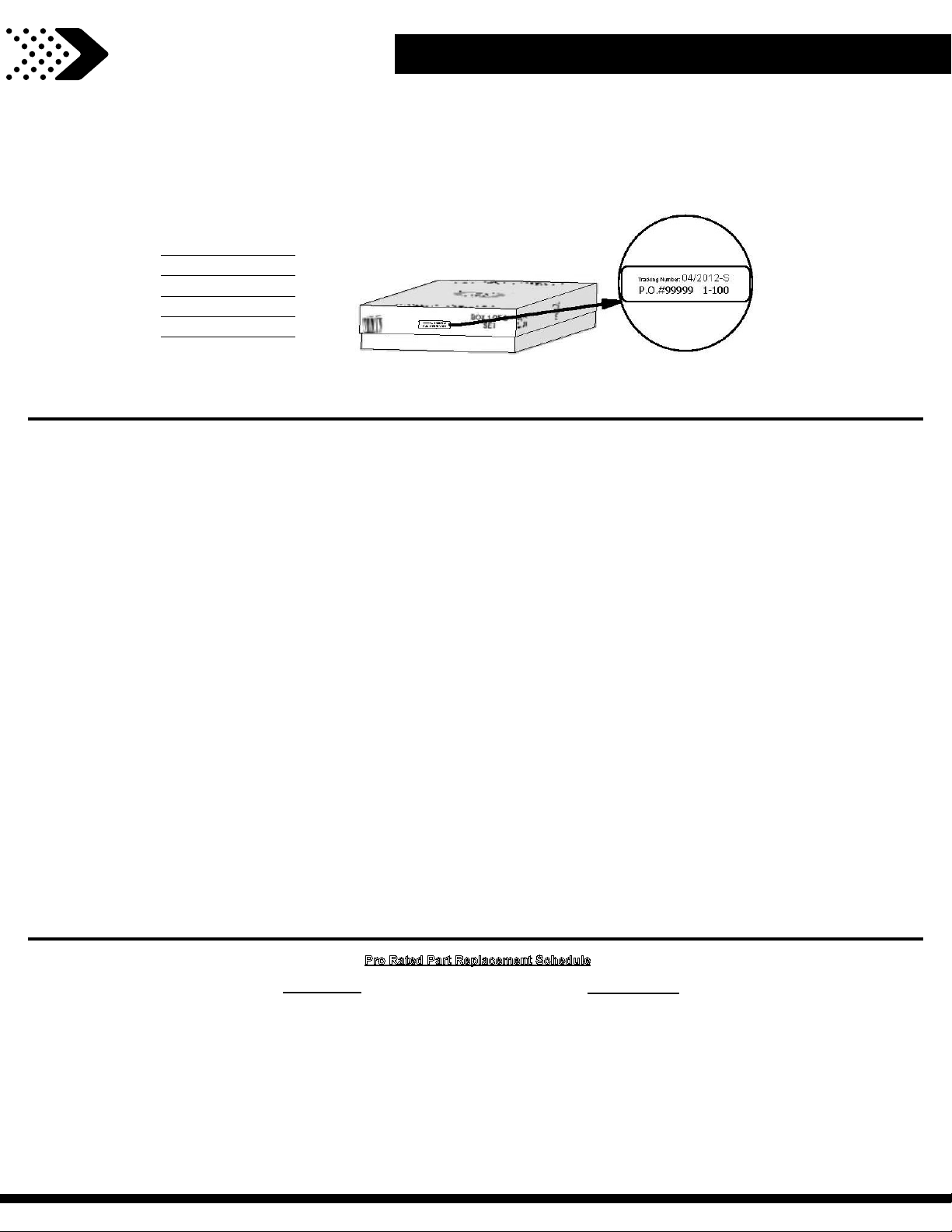
Track
ing Number:
Tracking Number Reference Label
Tracking ID nu
This Limited Warranty by Backyard Discovery applies to products manufactured under the Backyard Discovery brand or its other brands including but not limited to Backyard
Botanical, Adventure Playsets, and Leisure Time Products.
Backyard Discovery warrants that this product is free from defect in materials and workmanship for a period of one (1) year from the original date of purchase. This one (1) year
warranty covers all parts including wood, hardware, and accessories. All wood carries a ve (5) year pro-rated warranty against rot and decay. Refer to the schedule below for
charges associated with replacement of parts under this Limited Warranty. In addition, Backyard Discovery will replace any parts within the rst 30 days from date of purchase
found to be missing from or damaged in the original packaging.
mber on the carton and on the bottom of the vertical ID plate are included for tracking purposes associated with warranty claims.
This warranty applies to the original owner and registrant and is non-transferable. Regular maintenance is required to assure maximum life and performance of this product.
Failure by the owner to maintain the product according to the maintenance requirements may void this warranty. Maintenance guidelines are provided in the Owner’s Manual.
This Limited Warranty does not cover:
• Labor for any inspection
• Labor for replacement of any defective item(s)
• Incidental or consequential damages
• Cosmetic defects which do not a ect performance or integrity of a part or the entire product
• Vandalism, improper use, failure due to loading or use beyond the capacities stated in the applicable Assembly Manual.
• Acts of nature including but not limited to wind, storms, hail, oods, excessive water exposure
• Improper installation including but not limited to installation on uneven, unlevel, or soft ground
• Minor twisting, warping, checking, or any other natural occurring properties of wood that do not a ect performance or integrity
Backyard Discovery products have been designed for safety and quality. Any modi cations made to the original product could damage the structural integrity of the unit
leading to failure and possible injury. Modi cation voids any and all warranties and Backyard Discovery assumes no liability for any modi ed products or consequences
resulting from failure of a modi ed product.
This product is warranted for RESIDENTIAL USE ONLY. Under no circumstance should a Backyard Discovery product be used in public settings. Such use may lead to product
failure and potential injury. Any and all public use will void this warranty. Backyard Discovery disclaims all other representations and warranties of any kind, express or implied.
Pro Rated Part Replacement Schedule
Page 5

Owner’s Manual
5
Safety Warnings and Maintenance Instructions
WARNING
IT IS IMPORTANT TO CHECK AND TIGHTEN ALL HARDWARE AT THE BEGINNING AND DURING
THE SEASON AS THEY MAY LOOSEN DUE TO WOOD EXPANSION AND CONTRACTION.
• DO NOT climb or walk on the roof for any reason
• Requires two or more people to assemble safely
• Check for undergr
driving stakes into the ground.
• Check carefully for overhead lines and ensure there is
at least 6ft (2m) clearance from any overhead electrical
wires.
• Permanent structures may require a building permit.
As the purchaser and or installer of this product you are
advised to consult local planning, zoning and building
inspection departments for guidance on applicable
building codes and/or zoning requirements.
• Wood is NOT ame retardant and will burn. Grills, re pits
and chimineas are a re hazard if place too close to your
ound utilities before digging or
• Oil all metallic moving parts monthly during the usage
period.
• Check all coverings for bolts and sharp edges twice
monthly during usage season to be certain they are in
place. Replace when necessary. It is especially important
to do this at the beginning of each new season.
• For rusted areas on metallic members such as hinges,
brackets, etc. sand and repaint, using a non lead-based
paint meeting the requirements of Title 16 CRF Part 1303.
• Inspect wood parts monthly. The grain of the wood
sometimes will lift in the dry season causing splinters to
appear. Light sanding may be necessary to maintain a
safe environment. Treating your Product with protection
(sealant) after sanding will help prevent severe checking/
structure.
• Wear gloves to avoid injury during installation.
• During installation, follow all safety warnings provided
with your tools and use safety glasses.
• Check all nuts and bolts twice monthly during the usage
season and tighten as required.(But not so tight that you
crack the wood) It is particularly important that this
procedure be followed at the beginning of each season.
splitting and other weather damage.
• We have applied a waterborne translucent stain to your
unit. This is done for color only. Once or twice a year,
depending on your climate conditions, you must apply
some type of protection (sealant) to the wood of your unit.
Prior to the application of sealant, lightly sand any “rough”
spots on your set. Please note this is a requirement of
your warranty.
OWNERS SHALL BE RESPONSIBLE FOR MAINTAINING THE LEGIBILITY OF THE
WARNING LABELS
Page 6

Owner’s Manual
6
Instructions for Proper Maintenance
Your Backyard Discovery structure is designed and constructed of quality
materials. As with all outdoor products it
will weather and wear. To maximize
the enjoyment, safety and life of your structure it is important that you properly
maintain it.
About Our Wood
Backyard Discovery uses 100% Cedar (C. Lanceolata) wood. A
selecting the best quality lumber available, wood is still a product of nature and susceptible
to weathering which can change the appearance of your set.
What causes weathering? Does it a ect
the strength of my product?
One of the main reasons for weathering is the
e ects of water (moisture); the moisture content
of the wood at the surface is di erent than the
How can I reduce the amount of
weathering to wood product?
1. Your wood product is c
water-based stain. Sunlight will break down
the coating, so we recommend applying
lthough we take great care in
oated with a
interior of the wood. As the climate changes,
moisture moves in or out of the wood, causing
tension which can result in checking and or
warping. You can expect the following due to
weathering. These changes will not a ect the
strength of the product:
1. Checking is surface cracks in the wood along
the grain. A post (4” x 4”) will experience more
checking than a board (1” x 4”) because the surface
and interior moisture content will vary more widely
than in thinner wood.
2. Warping results from any distortion (twisting,
cupping) from the original plane of the board and
often happens from rapid wetting and drying of
the wood.
a water repellent or stain on a yearly basis
(see your local stain and paint supplier for a
recommended product). You must apply some
type of protection (sealant) to the wood of your
product. Please note this is a requirement
of your warranty. Most weathering is just
the normal result of nature and will not a ect
safety. However if you are concerned that a part
has experienced a severe weathering problem
please call our customer service department for
further assistance.
2. Inspect wood parts monthly. The grain of
the wood sometimes will lift in the dry season
causing splinters to appear. Light sanding may
be necessary to maintain a safe environment.
Treating your Product with protection (sealant)
after sanding will help prevent severe checking/
3. Fading happens as a natural change in the
wood color as it is exposed to sun-light and will
turn grey over time.
splitting and other weather damage.
Page 7
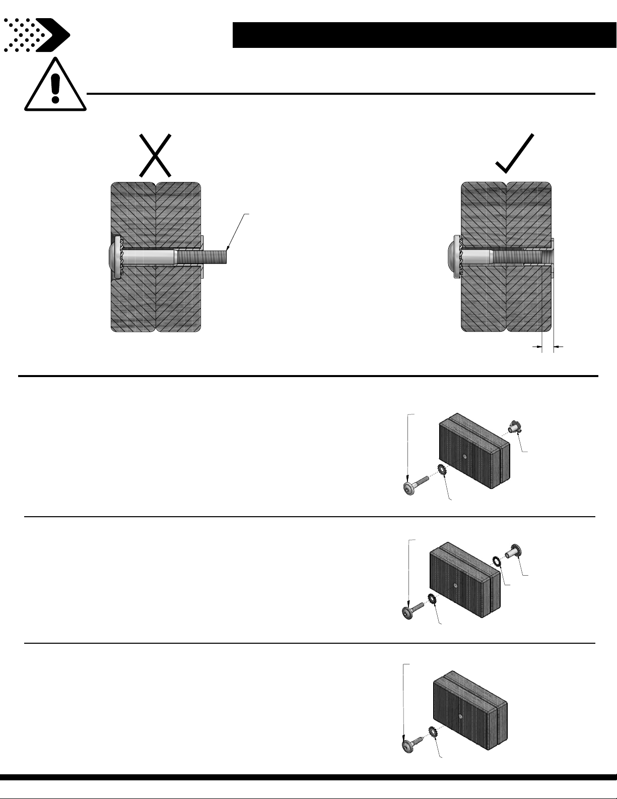
Protrusion Hazard
Proper Hardware Assembly
1/8”
CorrectIncorrect
Bolt and Barrel Nut Assembly
Insert barrel nut through the lock washer and press the pair
through the provided hole. Insert your bolt through the
second lock washer and insert the pair into the provided hole
opposite from the barrel nut. Turn clockwise to thread into the
barrel nut. Do not completely tighten until instructed.
LOCK WASHER
BOLT
BARREL NUT
Bolt and T-Nut Assembly
Tap T-nut into the provided hole. Insert your bolt through
the lock washer and insert into the provided hole opposite
from the T-Nut. Turn clockwise to thread into T-nut. Do not
completely tighten until instructed.
7187
LOCK WASHER
BOLT
Lag Assembly
Normally there will be a pre-drilled pilot hole on assemblies
that require a Lag Screw. If there is no pilot hole, line up the
two boards as they are to be attached and use the factory
drilled hole as a guide to drill another pilot hole into the
adjoining board. This will keep the wood from splitting. Only a
lock washer is required for steps with Lag Screws.
LOCK WASHER
LAG SCREW
If you see exposed
threads and your bolt
protrudes beyond the
T-Nut you may have over
tightened the bolt or
used incorrect hardware.
If you’ve overtightened,
remove the bolt and add
washers to eliminate the
protrusion.
Assembly Tips
Owner’s Manual
LOCK WASHER
7
Page 8
G2
G1
F2
F1
E1
E2
Owner’s Manual
8
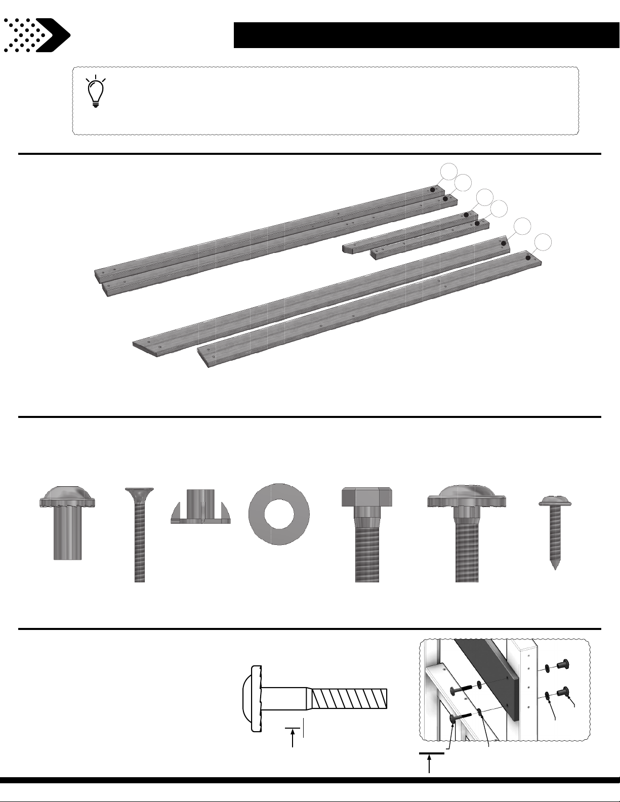
ASSEMBLY TIP:
Keep and eye out for these boxes which will contain helpful pictures and information making
the assembly process as quick and painless as possible
Assembly Tips
.
Sorting Wood
When removing the wood from the boxes we r
ecommend arranging them by part number before you begin
assembly. This will allow for faster assembly and easily identify any parts that may be missing or damaged.
Sorting Hardware
NUT BARREL
H100545
To help with assembly we recommend sorting your hardware bags with the seven digit alpha-numeric number
printed on the bags or by hardware type (i.e. bolts, nuts, etc.). Organizing your hardware will make assembly easier.
Hardware bags are printed with
a seven digit alpha-numeric part
number. During assembly you only
need to reference the last three
digits of the part number as noted
in each step. This will make nding
the correct hardware easier.
SCREW
H100695
T-NUT
H100699
WAS
HER FLAT
H100706
BOLT HEX
H100716
Hardware Identi cation
H100378
(x2)
BOLT WH
5/16 x 1-3/4
378
(x2)
BOLT
H100718
(x2)
198
SCREW PWH
H100742
192
(x2)
199
(x2)
Page 9
Owner's Manual
9
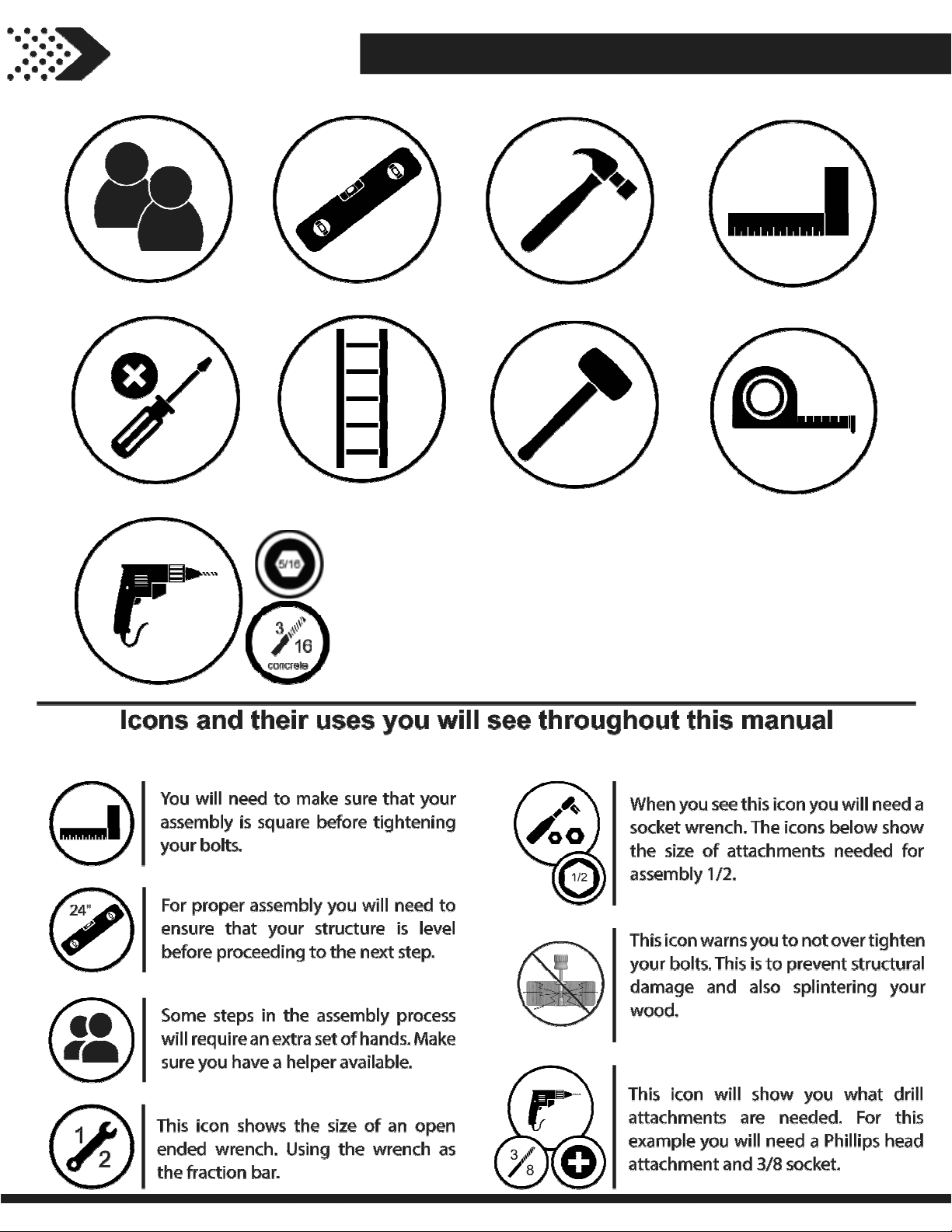
Tools Required for Installation
Page 10
Owner's Manual
10
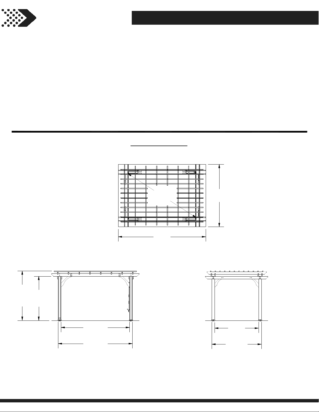
Basic Setup Dimensions & Assembly Notes
It is critically important that you start with square and level footings, concrete pad or deck to attach
your structure
• Pay close attention to the items needed for each step. Make sure you are using the correct hardware for each step.
Using incorrect hardware may result in improper assembly.
• Remember to double check for underground utilities and overhead electrical lines.
Post mounts are provided with your structure which allows you to permanently install your structure to a pre-existing
or new wood or concrete surface.
• The hardware to attach the post mounts to the structure is included.
• The hardware to mount the structure permanently to a concrete surface is included.
• The hardware to mount the structure permanently to a wood deck is NOT included and will need to be purchased
ately. You must ensure there is ample structural support under the deck before permanently attaching.
seper
Ground Dimension
EXAMPLE: 14' (4.3m) x 10' (3m) x 7' 11-1/8" (2.4m)
1
3
'
-
[
3
4
/
8
m
"
]
14'
m]
[4.3
7'-11 1/8"
[2.4 m]
7'- 3/4"
[2.2 m]
10'-11 1/2"
[3.3 m]
10'
[3 m]
7'- 1/2"
[2.1 m]
11'-10 5/8"
[3.6 m]
7'-11 1/2"
[2.4 m]
Page 11
Owner's Manual
11
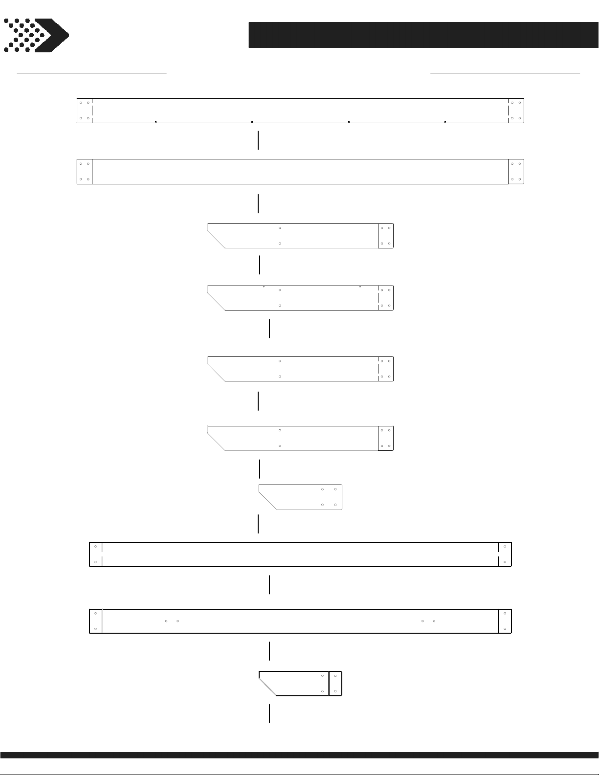
Wood Components (Not to Scale)
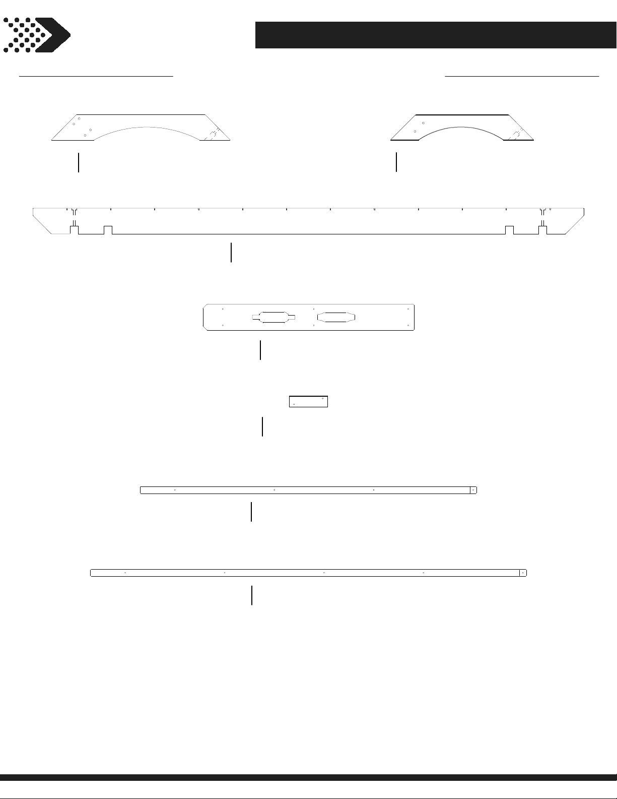
JOIST - W4L13476
D01
1 3/8"x5 1/4"x95 1/4" (36x134x2420)
(x2)
JOIST - W4L13485
D02
1 3/8"x5 1/4"x95 1/4" (36x134x2420)
(x2)
JOIST END - W4L13492
D03
1 3/8"x5 1/4"x39 3/4" (36x134x1008)
(x2)
Parts Identification
JOIST END - W4L13475
D04
1 3/8"x5 1/4"x39 3/4" (36x134x1008)
(x2)
JOIST END - W4L13484
D05
1 3/8"x5 1/4"x39 3/4" (36x134x1008)
(x2)
JOIST END - W4L13491
D06
1 3/8"x5 1/4"x39 3/4" (36x134x1008)
(x2)
JOIST END - W4L13494
D07
1 7/16"x5 1/4"x17 3/4" (36x134x451)
(x4)
JOIST - W4L13479
D08
1 3/8"x5 1/4"x90" (36x134x2286)
(x2)
JOIST - W4L13477
D09
1 3/8"x5 1/4"x90" (36x134x2286)
(x2)
JOIST END - W4L13474
D10
1 3/8"x5 1/4"x17 3/4" (36x134x451)
(x4)
Page 12
Owner's Manual
12
Wood Components (Not to Scale)
Parts Identification
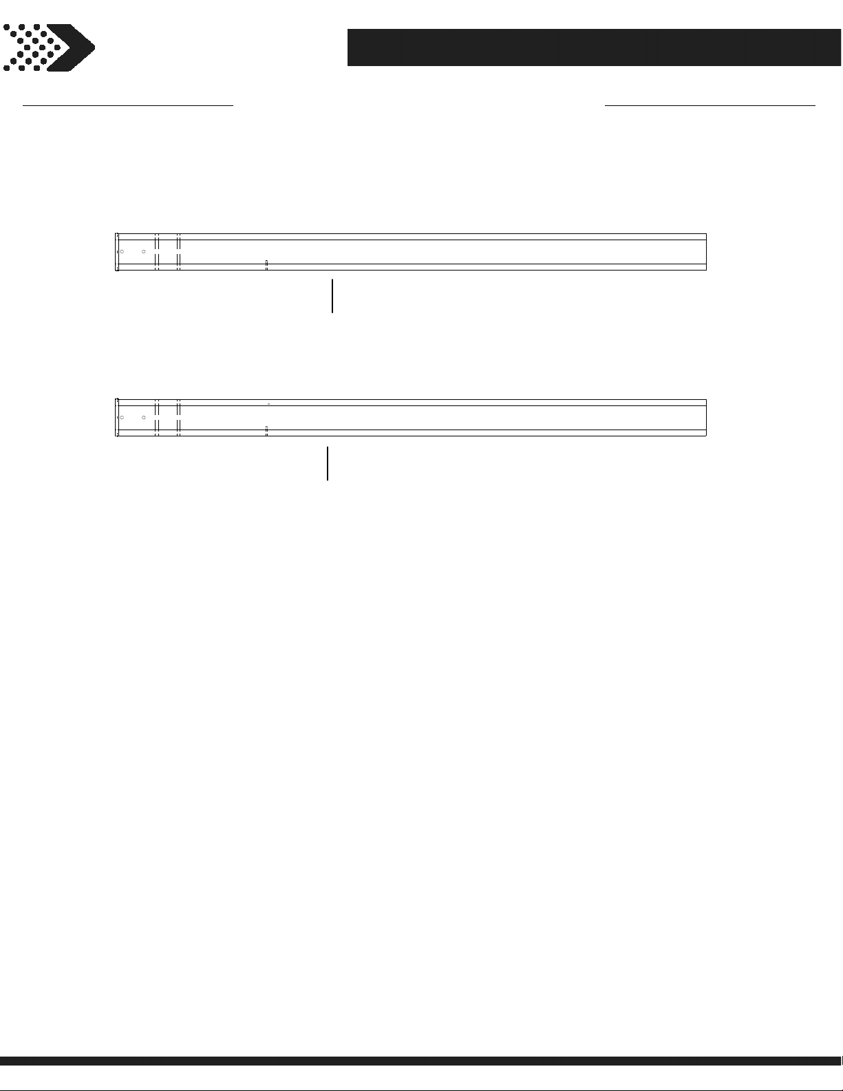
LONG ANGLE BRACE - W4L13482
D11
1 3/8"x5 1/4"x37 1/8" (36x134x942)
(x8)
SLOTTED JOIST - W4L13478
D13
1 3/8"x5 1/4"x114" (36x134x2896)
(x8)
CORD COVER - W4L13486
D14
1"x5 1/4"x43 5/8" (24x134x1109)
(x1)
CORD COVER - W4L13487
J01
1"x2 3/8"x7 7/8" (24x60x201)
(x1)
SHORT ANGLE BRACE - W4L13483
D12
1 3/8"x5 1/4"x29 3/4" (36x134x755)
(x4)
PURLIN - W4L13480
P01
1 3/8"x1 3/8"x69 5/8" (36x36x1768)
(x12)
PURLIN - W4L13481
P02
1 3/8"x1 3/8"x90 1/4" (36x36x2291)
(x12)
Page 13
Owner's Manual
13
Wood Components (Not to Scale)
Parts Identification
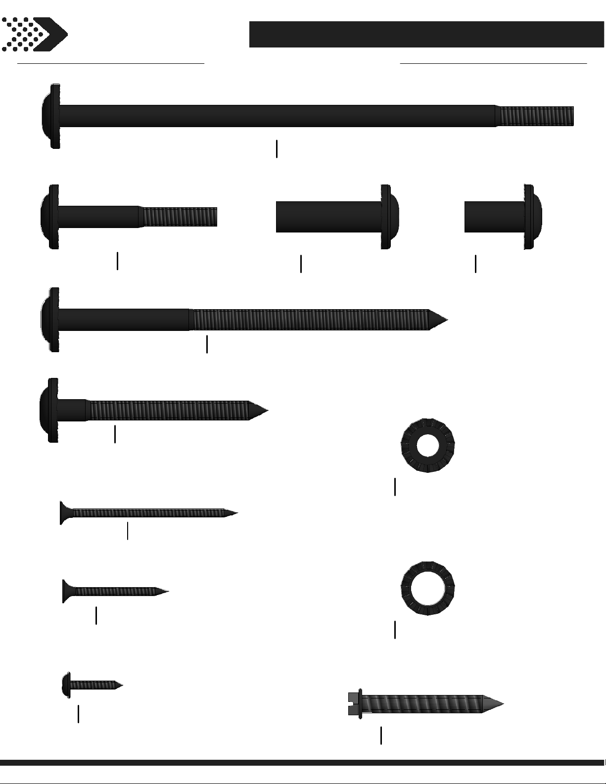
UP1
(x2)
UP2
(x2)
PERGOLA POST - W2A03006
5 1/2"x5 1/2"x89 1/2" (140x140x2273)
PERGOLA POST - W2A03008
5 1/2"x5 1/2"x89 1/2" (140x140x2273)
Page 14
Parts IdentificationOwner's Manual
14
Hardware Components
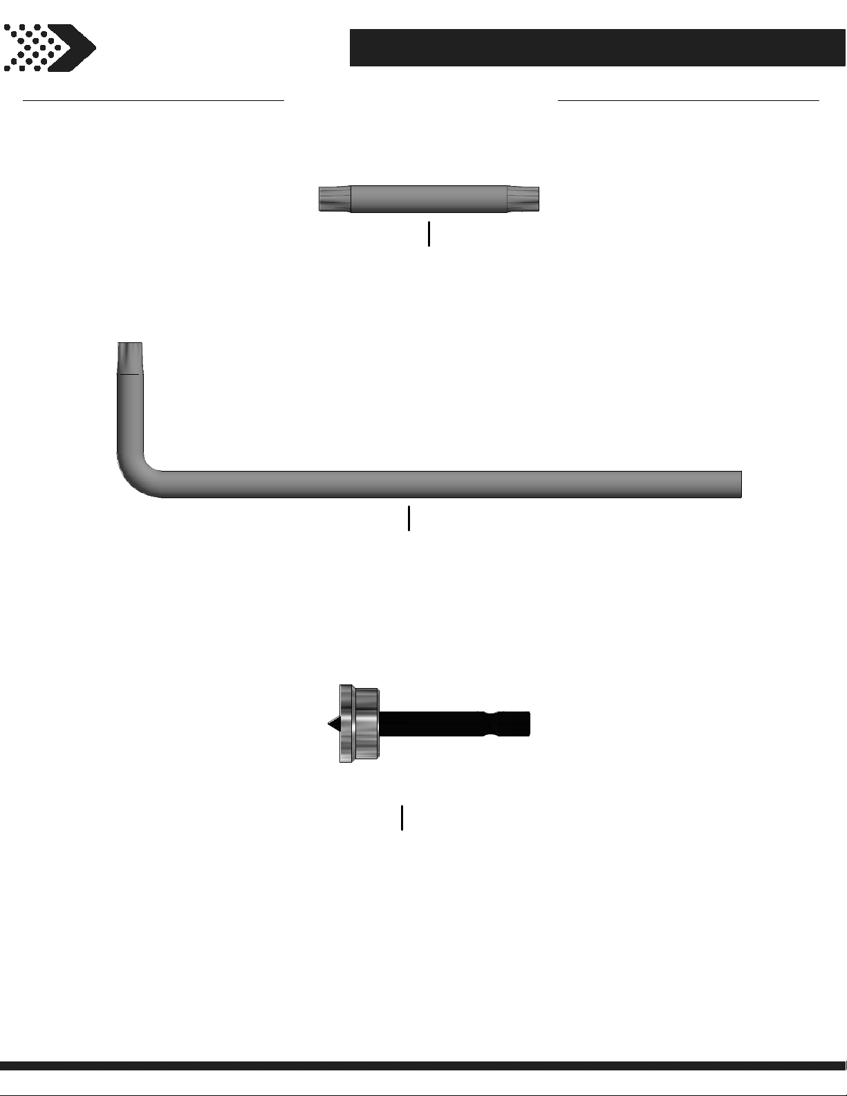
H100205
(x42)
H100206
(x13)
BOLT WH BLK
5/16x2-1/4
H100204
(x18)
LAG SCREW WH BLK
5/16x3
H100196
(x26)
LAG SCREW WH BLK
5/16x5 1/2
BOLT WH BLK
5/16x7-1/4
H100193
(x26)
NUT BARREL WH BLK
5/16x1-1/2
H100192
(x42)
NUT BARREL WH BLK
5/16x7/8
H100200
(x17)
H100392
(x4)
H100201
(x110)
SCREW PFH BLK
8x1 1/2
SCREW PWH BLK
8x3/4
SCREW PFH BLK
8x2-1/2
H100198
(x96)
H100199
(x68)
H100120
(x18)
WASHER LOCK EXT BLK
8x19
WASHER LOCK EXT BLK
12x19
SCREW CONCRETE ANCHOR
1/4x2
Page 15
Owner's Manual Parts Identification
15
Hardware Components
A100042
(x2)
A100041
(x2)
TORX BIT
T-40
TORX WRENCH
T-40
H100764
(x1)
SCREW SETTER
Page 16
Owner's Manual
16
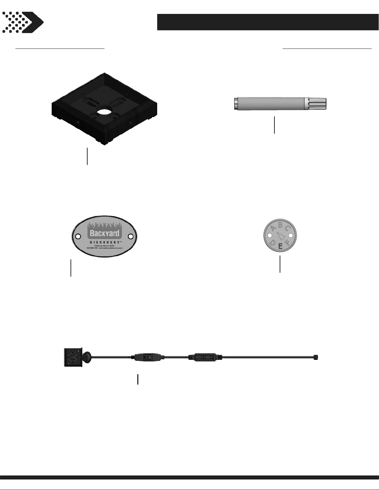
Accessory Components (Not to Scale)
Parts Identification
A100029
A100241
(x1)
FOOT 142 SQUARE POST
(x4)
BYD ID TAG (SMALL) WITHOUT AGES
A6P00173
(x1)
A100314
(x1)
STAIN MARKER
"A" REVISION TAG
A6P00265
(x1)
5' PERGOLA ELECTRICAL OUTLET ASSEMBLY
Page 17
STEP 1
17
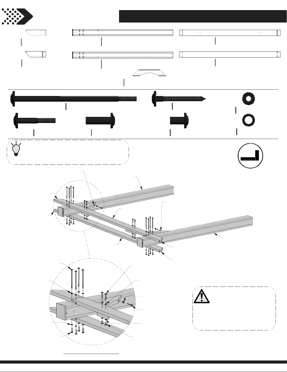
JOIST END - W4L13494
D07
1 7/16"x5 1/4"x17 3/4" (36x134x451)
(x4)
JOIST END - W4L13474
D10
1 3/8"x5 1/4"x17 3/4" (36x134x451)
(x4)
H100205
(x8)
BOLT WH BLK
5/16x2-1/4
TIP:
LAY PARTS ON GROUND OR SAW HORSES
FOR EASE OF ASSEMBLY.
SHORT ANGLE BRACE
H100196
(x16)
D12
BOLT WH BLK
5/16x7-1/4
H100193
(x16)
(x1)
PERGOLA POST - W2A03006
UP1
5 1/2"x5 1/2"x89 1/2" (140x140x2273)
(x2)
PERGOLA POST - W2A03008
UP2
5 1/2"x5 1/2"x89 1/2" (140x140x2273)
(x2)
SHORT ANGLE BRACE - W4L13483
D12
1 3/8"x5 1/4"x29 3/4" (36x134x755)
(x4)
NUT BARREL WH BLK
5/16x1-1/2
UP2
(x1)
PERGOLA POST
H100206
(x4)
H100192
(x8)
LAG SCREW WH BLK
5/16x3
NUT BARREL WH BLK
5/16x7/8
JOIST - W4L13477
D09
1 3/8"x5 1/4"x90" (36x134x2286)
(x2)
JOIST - W4L13479
D08
1 3/8"x5 1/4"x90" (36x134x2286)
(x2)
H100198
(x28)
H100199
(x24)
WASHER LOCK EXT BLK
8x19
WASHER LOCK EXT BLK
12x19
D07
(x1)
JOIST END
D10
(x1)
JOIST END
196
(x4)
BOLT - 7-1/4
198
(x4)
WASHER - 8x19
199
(x4)
WASHER - 12x19
193
(x4)
NUT BARREL - 1 1/2"
D08
JOIST
(x1)
D09
(x1)
JOIST
205
(x2)
BOLT - 2 1/4"
198
(x2)
WASHER - 8x19
198
WASHER - 8x19
206
LAG SCREW - 3"
199
WASHER - 12x19
192
(x2)
NUT BARREL - 7/8"
D12
(x1)
SHORT ANGLE BRACE
D10
JOIST END
D07
JOIST END
(x1)
(x1)
(x2)
(x1)
(x1)
UP1
(x1)
PERGOLA POST
NOTES:
1. REPEAT THIS STEP
ICE FOR OTHER SIDE.
TW
2. ASSEMBLE AS SHOWN
USING THE PRE-DRILLED
PILOT HOLES IN POSTS.
REPEAT ON OPPOSITE END
Page 18
STEP 2
18
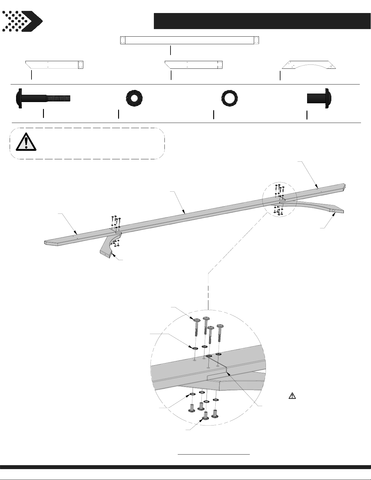
JOIST - W4L13485
D02
1 3/8"x5 1/4"x95 1/4" (36x134x2420)
(x2)
JOIST END - W4L13492
D03
1 3/8"x5 1/4"x39 3/4" (36x134x1008)
(x2)
H100205
(x16)
BOLT WH BLK
5/16x2-1/4
NOTES:
REPEAT STEP TO COMPLETE TWO
INNER JOIST ASSEMBLIES.
D03
(x1)
JOIST END
H100198
(x16)
D05
(x2)
WASHER LOCK EXT BLK
8x19
D02
(x1)
JOIST
JOIST END - W4L13484
1 3/8"x5 1/4"x39 3/4" (36x134x1008)
H100199
(x16)
WASHER LOCK EXT BLK
12x19
LONG ANGLE BRACE - W4L13482
D11
1 3/8"x5 1/4"x37 1/8" (36x134x942)
(x4)
D05
H100192
(x16)
(x1)
NUT BARREL WH BLK
5/16x7/8
JOIST END
D11
(x1)
LONG ANGLE BRACE
D11
(x1)
LONG ANGLE BRACE
BOLT - 2 1/4"
198
(x4)
WASHER - 8x19
199
WASHER - 12x19
NUT BARREL - 7/8"
205
(x4)
(x4)
192
NOTE OVERLAP AND
BOARD ORIENTATION.
(x4)
REPEAT ON OPPOSITE END
Page 19
STEP 3
19
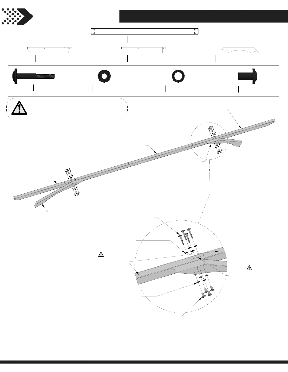
JOIST - W4L13476
D01
1 3/8"x5 1/4"x95 1/4" (36x134x2420)
(x2)
JOIST END - W4L13475
D04
1 3/8"x5 1/4"x39 3/4" (36x134x1008)
(x2)
H100205
(x16)
BOLT WH BLK
5/16x2-1/4
NOTES:
REPEAT STEP TO COMPLETE TWO
OUTER JOIST ASSEMBLIES.
D04
(x1)
JOIST END
H100198
(x16)
JOIST END - W4L13491
D06
1 3/8"x5 1/4"x39 3/4" (36x134x1008)
(x2)
WASHER LOCK EXT BLK
8x19
D01
(x1)
JOIST
H100199
(x16)
WASHER LOCK EXT BLK
12x19
D11
LONG ANGLE BRACE
D11
(x4)
D06
JOIST END
(x1)
LONG ANGLE BRACE - W4L13482
1 3/8"x5 1/4"x37 1/8" (36x134x942)
(x1)
H100192
(x16)
NUT BARREL WH BLK
5/16x7/8
D11
(x1)
LONG ANGLE BRACE
NOTE PILOT HOLES
ON TOP OF JOIST.
BOLT - 2 1/4"
198
(x4)
WASHER - 8x19
199
WASHER - 12x19
205
(x4)
(x4)
192
(x4)
NUT BARREL - 7/8"
REPEAT ON OPPOSITE END
NOTE OVERLAP AND
BOARD ORIENTATION.
Page 20
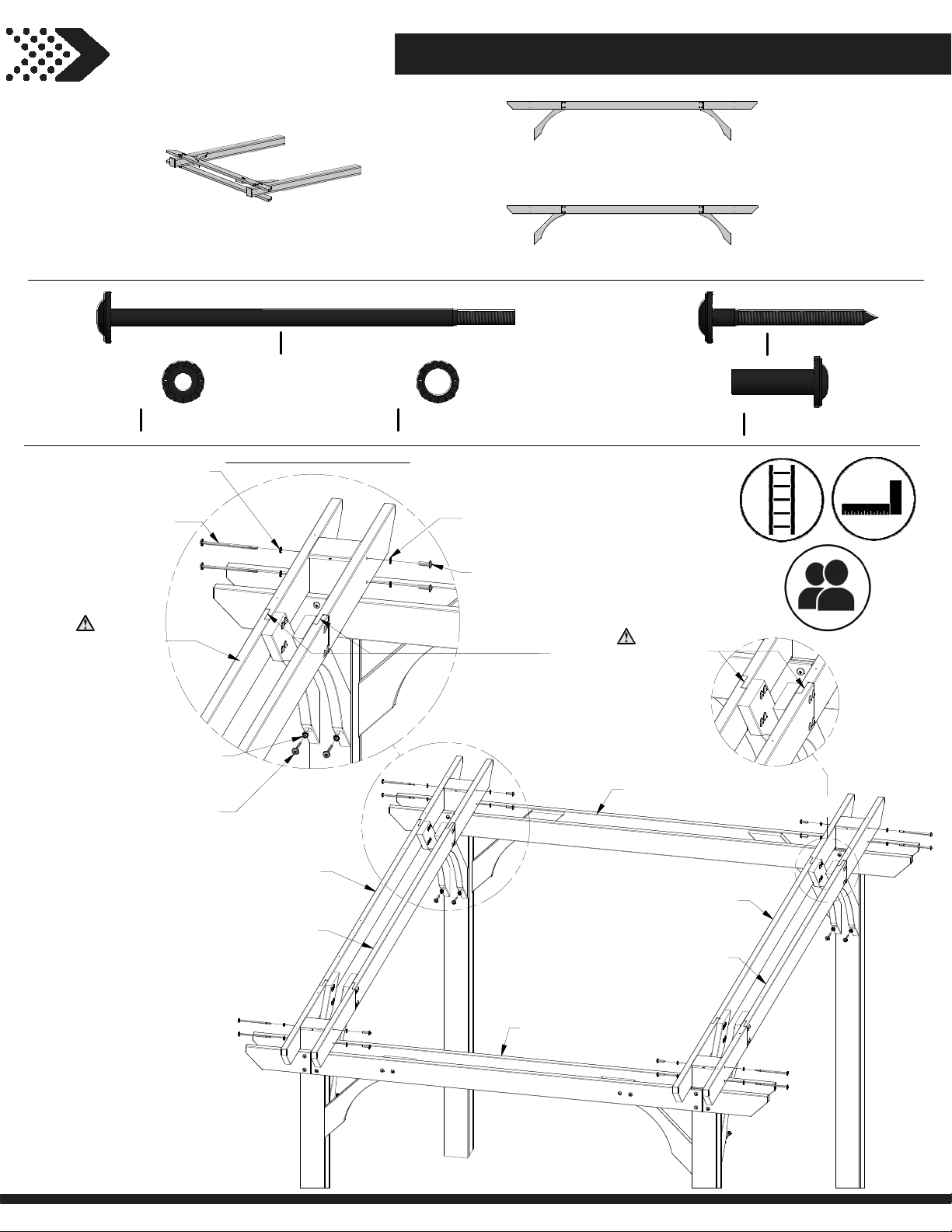
STEP 4
20
UPRIGHT ASSEMBLY
(x2)
FROM
PREVIOUS STEPS
OUTER JOIST ASSEMBLY
(x2)
FROM PREVIOUS STEPS
INNER JOIST ASSEMBLY
(x2)
FROM PREVIOUS STEPS
H100198
(x16)
WASHER LOCK EXT BLK
8x19
198
WASHER - 8x19
196
(x2)
BOLT - 7-1/4
NOTE PILOT HOLES
ON TOP OF THE
OUTER JOIST
ASSEMBLY
WASHER - 8x19
LAG SCREW - 3"
198
206
H100196
REPEAT ON EACH CORNER
(x2)
(x2)
(x2)
(x8)
BOLT WH BLK
5/16x7-1/4
H100199
(x8)
WASHER LOCK EXT BLK
12x19
199
(x2)
WASHER - 12x19
193
(x2)
NUT BARREL - 1 1/2"
H100193
NOTE JOIST OVERLAP
DIRECTION FOR
PROPER ASSEMBLY.
UPRIGHT
ASSEMBLY
H100206
(x8)
NUT BARREL WH BLK
(x8)
5/16x1-1/2
LAG SCREW WH BLK
5/16x3
OUTER JOIST
ASSEMBLY
INNER JOIST
ASSEMBLY
INNER JOIST
ASSEMBLY
OUTER JOIST
ASSEMBLY
UPRIGHT
ASSEMBLY
Page 21
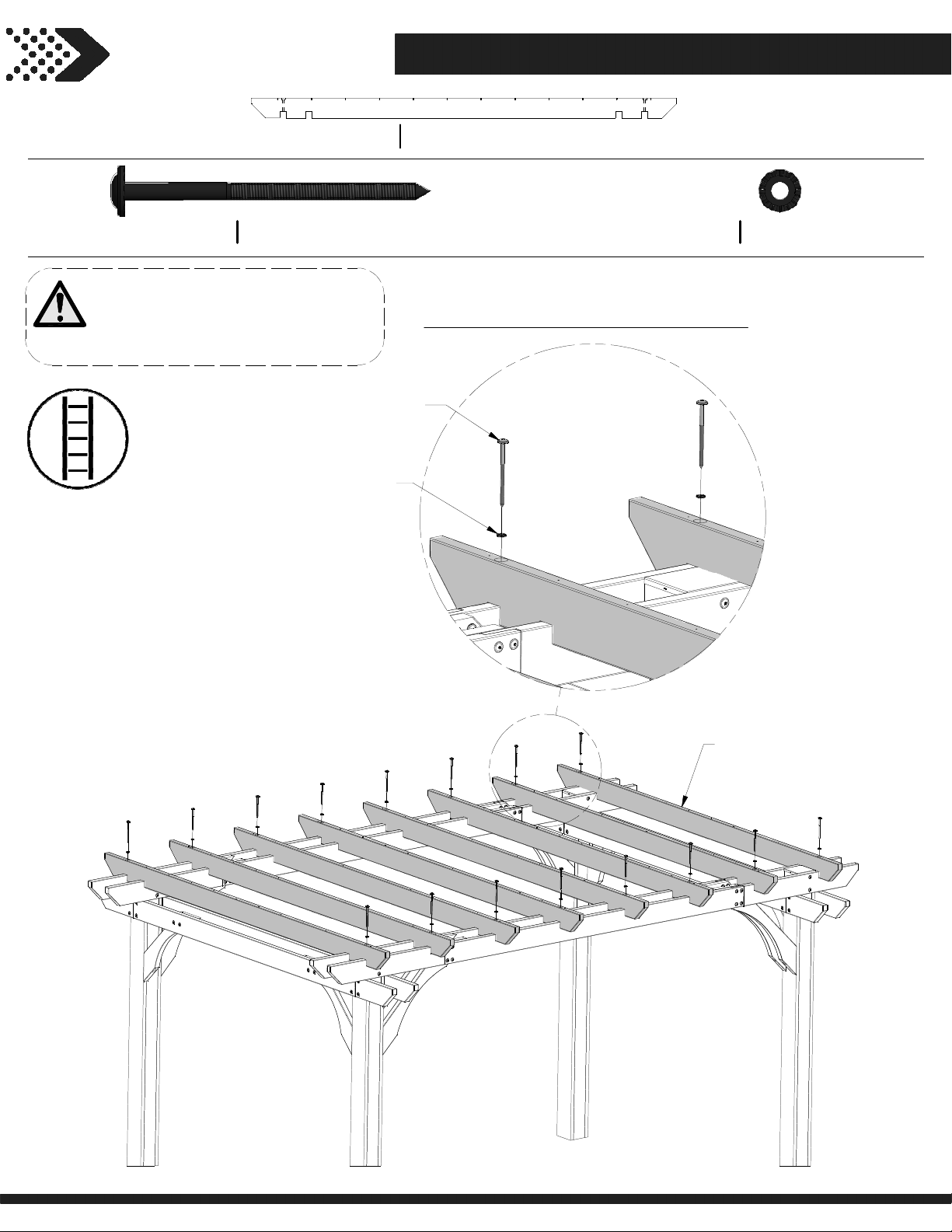
STEP 5
21
SLOTTED JOIST - W4L13478
D13
1 3/8"x5 1/4"x114" (36x134x2896)
(x8)
H100204
(x16)
LAG SCREW WH BLK
5/16x5 1/2
NOTES:
LOCATE AND USE PILOT HOLES IN
THE OUTER JOISTS TO MOUNT D13
BOARDS AS SHOWN.
LAG SCREW - 5 1/2"
198
WASHER - 8x19
204
(x1)
REPEAT ON OPPOSITE END AND ON ALL JOISTS
(x1)
H100198
(x16)
WASHER LOCK EXT BLK
8x19
D13
(x8)
SLOTTED JOIST
Page 22
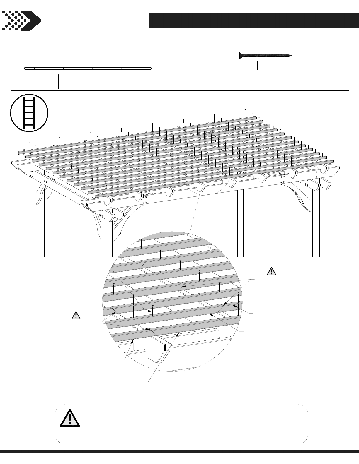
STEP 6
22
P01
(x12)
P02
(x12)
PURLIN - W4L13480
1 3/8"x1 3/8"x69 5/8" (36x36x1768)
PURLIN - W4L13481
1 3/8"x1 3/8"x90 1/4" (36x36x2291)
H100201
(x96)
SCREW PFH BLK
8x2-1/2
201
(x96)
SCREW - 2 1/2"
ANGLE CUT
P01
PURLIN
NOTES:
ASSEMBLE P01 & P02 BOARDS BY ALTERNATING THEM AS YOU WORK
ACROSS THE JOIST BOARDS. AS SHOWN THE ANGLE CUT IN THE P01 &
P02 BOARDS SHOULD ALTERNATE WHICH JOIST THEY LAND ON WHEN
ASSEMBLED.
(x12)
P02
PURLIN
ANGLE CUT
P01
PURLIN
P02
PURLIN
(x12)
Page 23
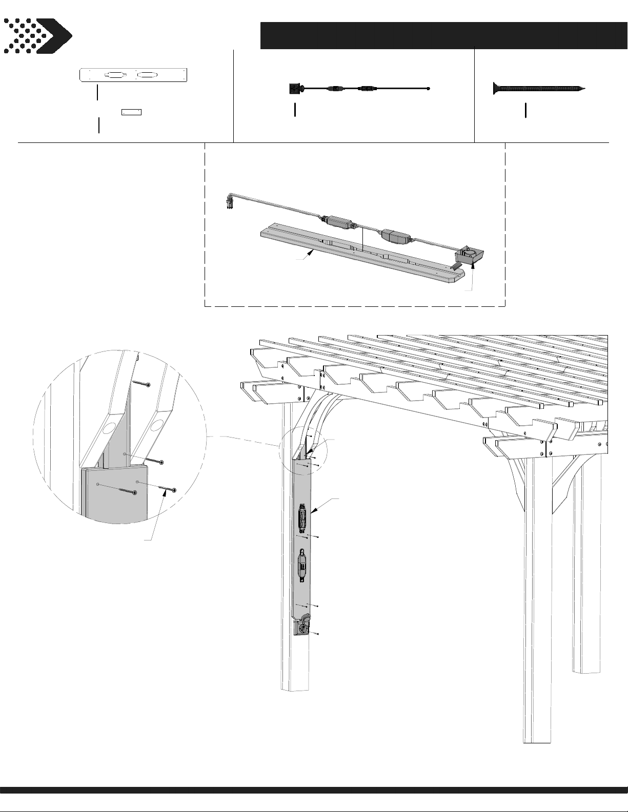
STEP 7
23
CORD COVER - W4L13486
D14
1"x5 1/4"x43 5/8" (24x134x1109)
(x1)
CORD COVER - W4L13487
J01
1"x2 3/8"x7 7/8" (24x60x201)
(x1)
A6P00265
5' PERGOLA ELECTRICAL OUTLET ASSEMBLY
(x1)
PRESS THE ELECTRICAL CORD ASSEMBLY
INTO THE CUT OUTS ON THE D14 CORD
COVER, AS SHOWN.
D14
(x1)
CORD COVER
265
5' PERGOLA ELECTRICAL OUTLET ASSEMBLY
(x1)
H100201
(x10)
SCREW PFH BLK
8x2-1/2
201
(x10)
SCREW - 2 1/2"
J01
(x1)
CORD COVER
D14
CORD COVER
Page 24
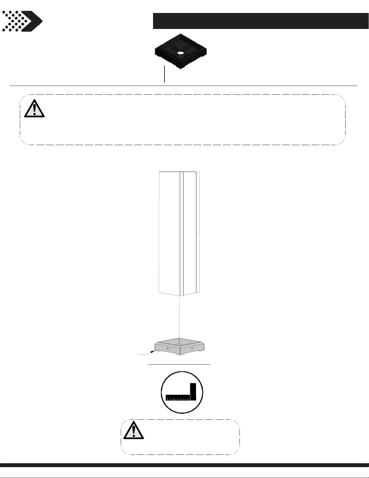
STEP 8
24
A100029
(x4)
FOOT 142 SQUARE POST
NOTES:
DECIDE WHERE TO PLACE THE PERGOLA. NOTE THIS MOUNTING PROCEDURE IS MEANT TO BE
USED
ON CONCRETE ONLY.
PLACE THE PERGOLA EXACTLY WHERE IT WILL BE ANCHORED WHEN COMPLETED AND SLIDE A
FOOT UNDER EACH POST.
029
(x1)
FOOT 142 SQUARE POST
REPEAT ON ALL POSTS
NOTES:
SQUARE POSTS AND
TEN ALL BOLTS AND
TIGH
SCREWS AT THIS TIME.
Page 25
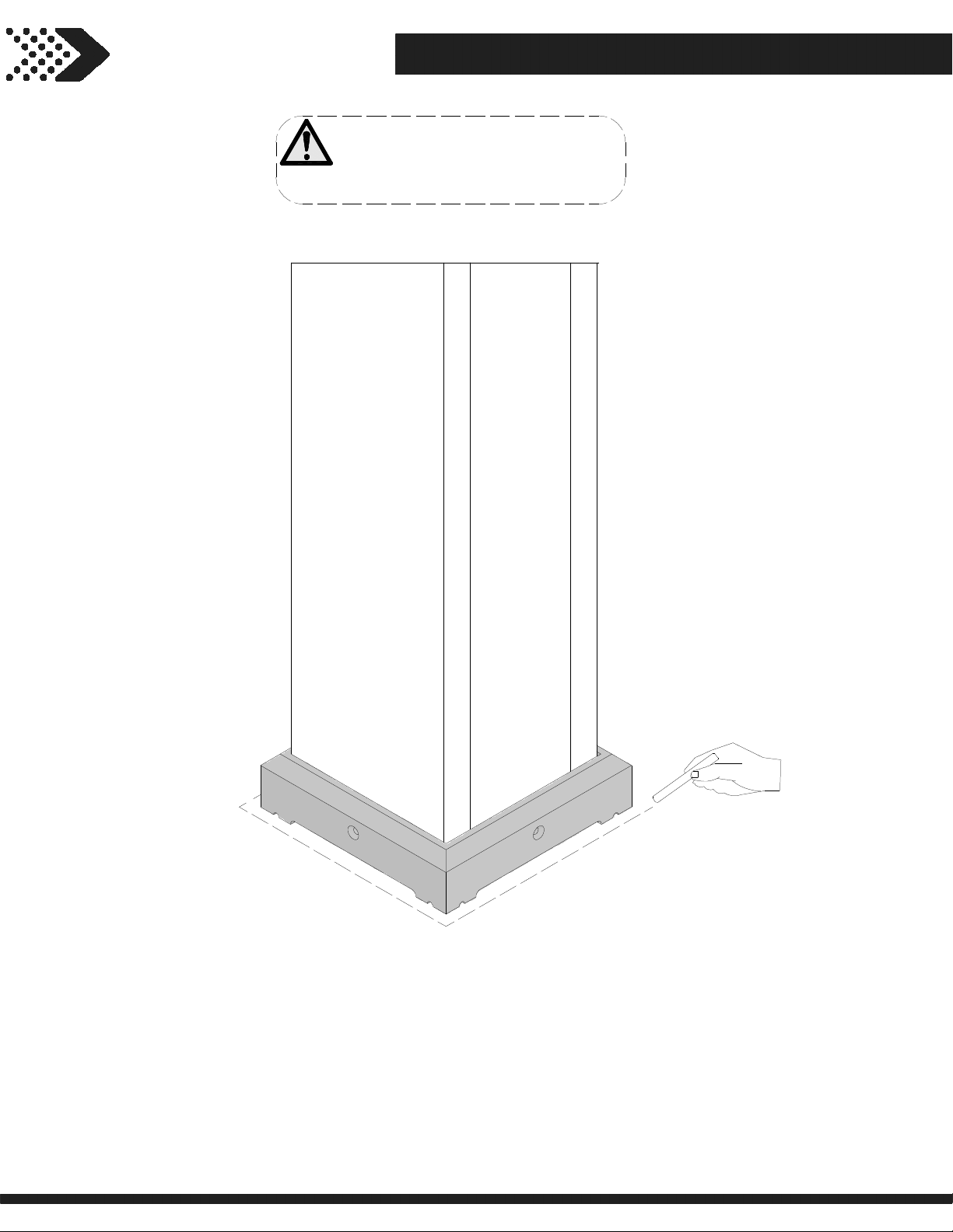
STEP 9
25
NOTES:
USE CHALK TO TRACE AROUND
THE EDGES OF EACH FOOT TO
MARK THE FEET LOCATIONS.
Page 26
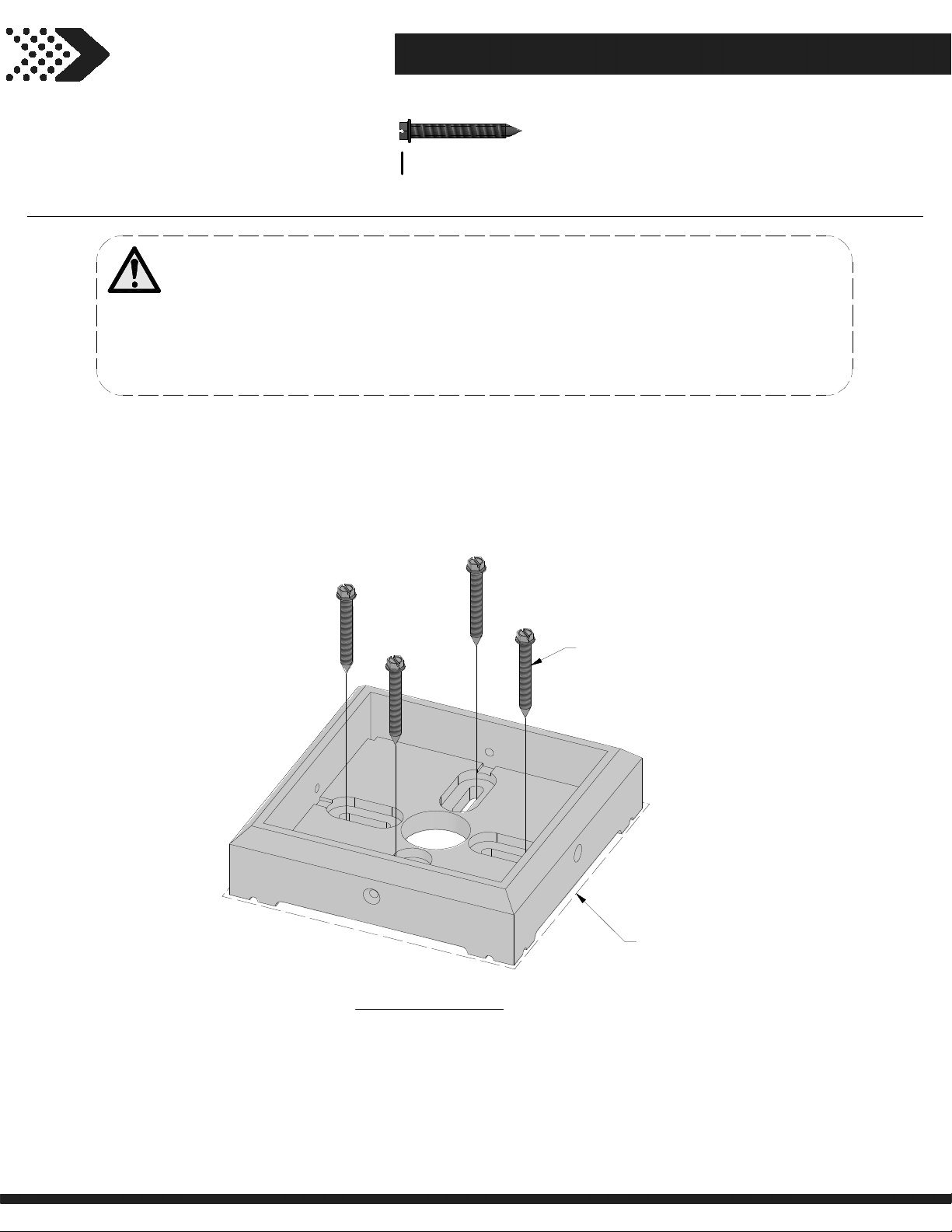
STEP 10
26
H100120
(x16)
SCREW CONCRETE ANCHOR
1/4x2
NOTES:
MOVE THE PERGOLA ASIDE AND PLACE EACH FOOT INSIDE THE LINES DRAWN IN THE
PREV
IOUS STEP. NOW, USE A 3/16" CONCRETE DRILL BIT TO DRILL PILOT HOLES INTO
THE CONCRETE PAD.
NEXT, USE THE PROVIDED CONCRETE ANCHORS TO ATTACH EACH FOOT TO THE
CONCRETE SURFACE.
REPEAT ON ALL FEET
120
(x4)
SCREW - 2"
CHALK LINE
Page 27
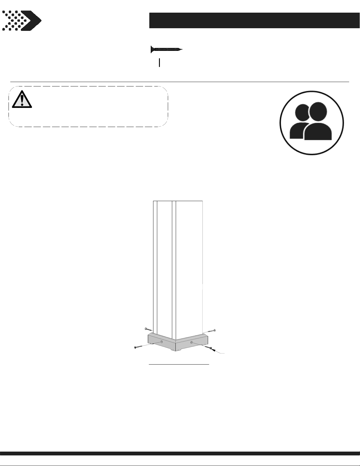
STEP 11
27
H100200
(x16)
NOTES:
MOVE THE PERGOLA BACK INTO PLACE,
TING EACH POST INSIDE A FOOT AND
SET
MOUNT AS SHOWN USING THE PROVIDED
HARDWARE.
SCREW PFH BLK
8x1 1/2
REPEAT ON ALL POSTS
200
(x4)
SCREW - 1 1/2"
Page 28
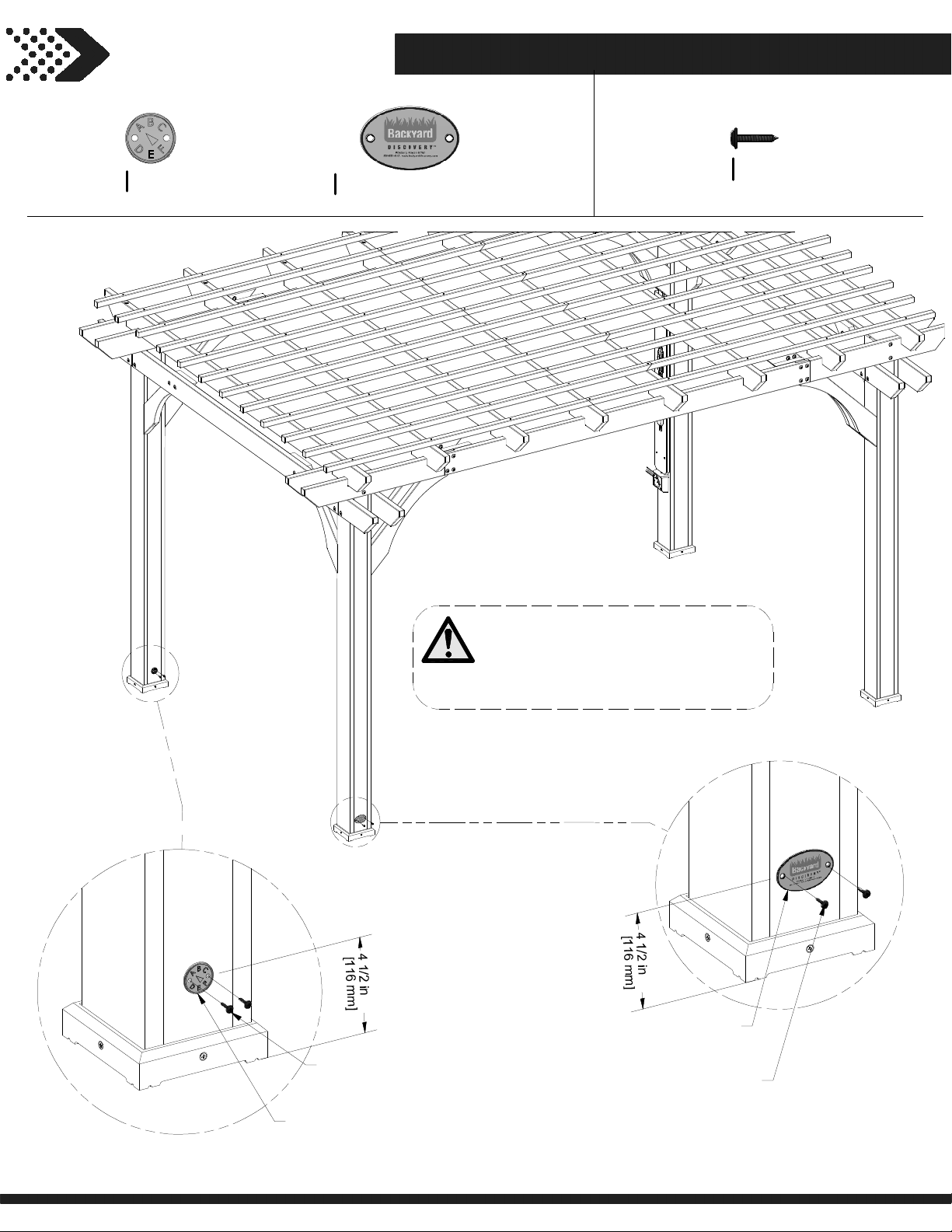
STEP 12
28
A100314
(x1)
"A" REVISION TAG
A100241
(x1)
BYD ID TAG (SMALL) WITHOUT AGES
H100392
(x4)
SCREW PWH BLK
8x3/4
392
(x2)
SCREW - 3/4"
314
(x1)
"A" REVISION TAG
NOTES:
CENTER THE REVISION TAG AND ID
TAG ON THE POST AND CENTER
VERTICALLY APPROX. 4-1/2" FROM
THE GROUND.
241
(x1)
BYD ID TAG (SMALL) WITHOUT AGES
392
SCREW - 3/4"
(x2)
 Loading...