

Page 1
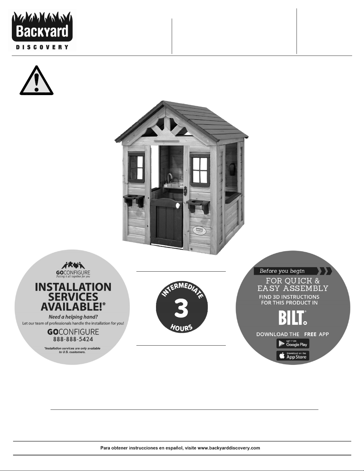
Sweetwater
Model # 2001312
WARNING
Adult Assembly Required.
Not suitable for children under
two years, due to sharp points
and small parts.
Playhouse
Owner's Manual & Assembly Instructions
MANUFACTURED BY:
Backyard Discovery
3305 Airport Drive
Pittsburg, KS 66762
800-856-4445
average 2 person assembly time
assembly time may vary based on skill level
For the most up to date assembly manual,
to register your set, or to order replacement parts please visit
www.backyarddiscovery.com
SAVE THIS ASSEMBLY MANUAL FOR FUTURE REFERENCE IN THE EVENT THAT
YOU NEED TO ORDER REPLACEMENT PARTS.
Made in China | INS-2001312-A-SWEETWATER-ENG 10/08/19
Page 2
• 18+ Years of Experience Servicing Big Box Retailers and Direct Consumers
• Highly Skilled, Specialized, Courteous, Professional Service Technicians
• Over 140,000 Installations Annually
• Satisfaction Guarantee
•
Flexible Appointments, including weekends
• Coverage across the nation
• White Glove Service
Visit www.gocongure.com for more info!
*Installation services are only available to U.S. customers.
With Go Con! gure, we bring you 18 years of experience right to your doorstep.
We service a wide array of indoor and outdoor recreation products that most consumers
don’t have the time or ability to deliver & install themselves.
We do the heavy lifting, so you don’t have to!
*Installation services are only available
to U.S. customers.
INSTALLATION
SERVICES
AVAILABLE!
*
Need a helping hand?
Let our team of professionals handle the installation for you!
2
Page 3
MISSING A PART?
CALL US BEFORE GOING
BACK TO THE STORE
Own
3
er’s Manual
Please Read This Before Starting Assembly
The store where you made your purchase
does not stock parts f
or this item.
If you have assembly questions or you are missing or
have damaged parts, please call
1-800-856-4445
you can also visit www.backyarddiscovery.com
or e-mail customerser
Please have the following information ready when you make your call:
• Model Number of the product located on the front of the assembly manual
• The item description and number from the parts list from the manual that was included in your box
• Read entire assembly manual, paying special attention to the important tips and safety information.
• To ensure there are no missing pieces do a complete inventory by rst separating and identifying all parts.
• Make sure to check packing material for small parts that may have fallen out during shipment.
• Structures are not intended for public use. The Company does not warranty any of its residential structures
subjected to commercial use.
• This manual contains helpful information concerning assembly preparation, installation procedure and
required maintenance.
• Always keep safety in mind as your structure is being built.
• Keep these instructions for future reference.
Page 4
Product Age
Customer Pays
All Parts
0-30 days from date of purchase $0 and free shipping
31 days to 1 year $0 + S&H
Wood Rot and Decay Only
1 year $0 and free shipping
2 year 20% + S&H
3 year 40% + S&H
4 year 60% + S&H
5 year 80% + S&H
Over 5 years 100% + S&H
Owner’s Manual
4
Limited
Warranty
Please read entire booklet completely before beginning the assembly process
Pl
ease retain these instructions and your receipt for future reference. Keep them in a safe place where you can refer to them as needed.
In order to provide you with the most e cient service, it is required that you provide us with the part numbers when ordering parts.
For Your Records:
Please take time and
ll out the information below. This information will be needed for warranty issues.
Where Purchased:
Dat
e of Purchase:
Installation Date:
Installed by:
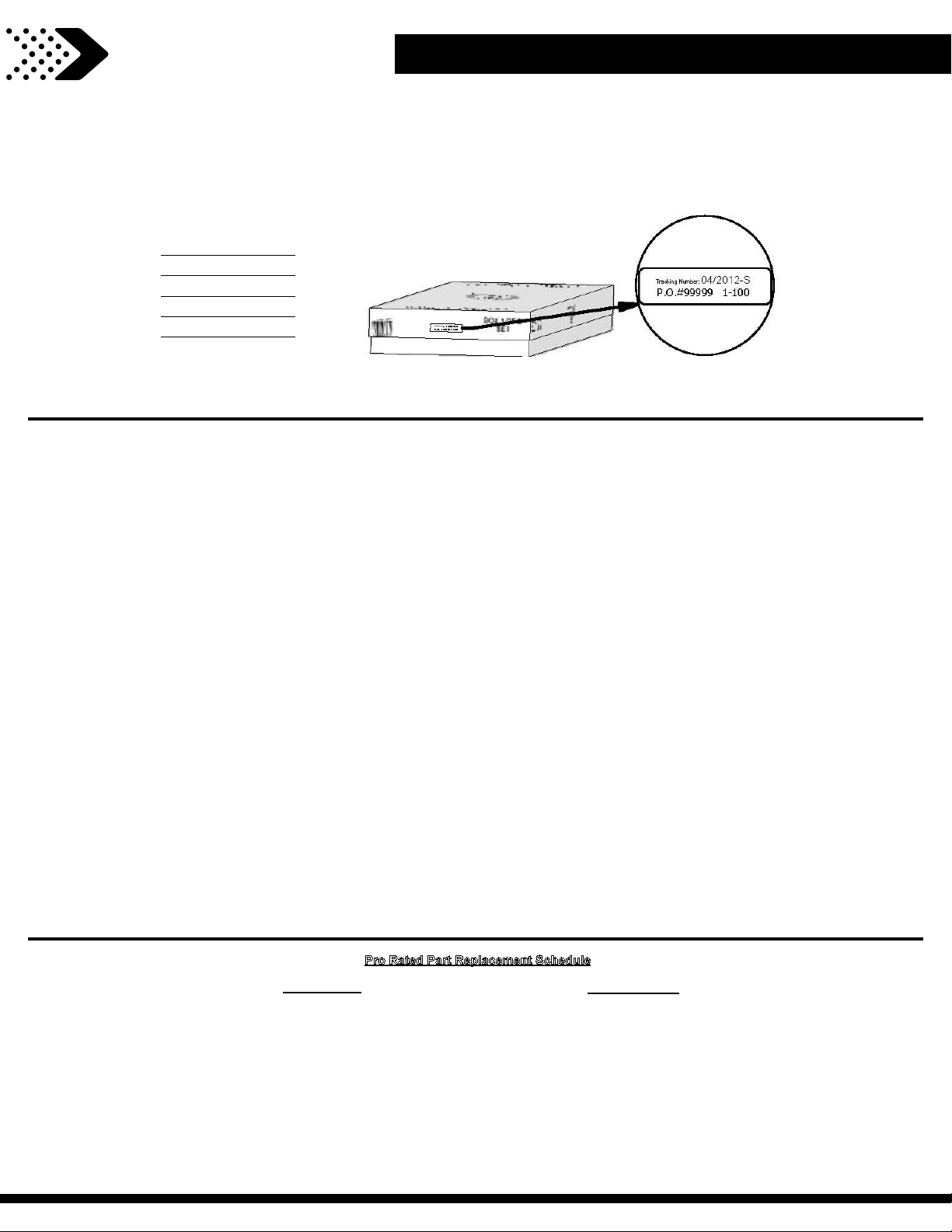
Tracking Number:
Tracking Number Reference Label
Tr
acking ID number on the carton and on the bottom of the vertical ID plate are included for tracking purposes associated with warranty claims.
This Limited Warranty by Backyard Discovery applies to products manufactured under the Backyard Discovery brand or its other brands including but not limited t
Botanical, Adventure Playsets, and Leisure Time Products.
Backyard Discovery warrants that this product is free from defect in materials and workmanship for a period of one (1) year from the original date of purchase. This one (1) year
warranty covers all parts including wood, hardware, and accessories. All wood carries a ! ve (5) year pro-rated warranty against rot and decay. Refer to the schedule below for
charges associated with replacement of parts under this Limited Warranty. In addition, Backyard Discovery will replace any parts within the ! rst 30 days from date of purchase
found to be missing from or damaged in the original packaging.
This warranty applies to the original owner and registrant and is non-transferable. Regular maintenance is required to assure maximum life and performance of this product.
Failure by the owner to maintain the product according to the maintenance requirements may void this warranty. Maintenance guidelines are provided in the Owner’s Manual.
This Limited Warranty does not cover:
• Installation
• Labor for any inspection
• Labor for replacement of any defective item(s)
• Incidental or consequential damages
• Cosmetic defects which do not a ect performance or integrity of a part or the entire product
• Vandalism, improper use, failure due to loading or use beyond the capacities stated in the applicable Assembly Manual.
• Acts of nature including but not limited to wind, storms, hail, oods, excessive water exposure
• Improper installation including but not limited to installation on uneven, unlevel, or soft ground
• Minor twisting, warping, checking, or any other natural occurring properties of wood that do not a ect performance or integrity
Backyard Discovery products have been designed for safety and quality. Any modi cations made to the original product could damage the structural integrity of the unit
leading to failure and possible injury. Modi cation voids any and all warranties and Backyard Discovery assumes no liability for any modi ed products or consequences
resulting from failure of a modi ed product.
o Backyard
This product is warranted for RESIDENTIAL USE ONLY. Under no circumstance should a Backyard Discovery product be used in public settings. Such use may lead to product
failure and potential injury. Any and all public use will void this warranty. Backyard Discovery disclaims all other representations and warranties of any kind, express or implied.
Pro Rated Part Replacement Schedule
Page 5
Owner’s Manual
5
Operating Instructions and Safety Warnings
NOTE:
Your Children
Observe the following statements and warnings to reduce
of serious or fatal injury. Please review these safety rules regularly with
’s Safety Is Our #1 Concern!
the likelihood
your children.
WARNING:
BUR
N HAZARD
• Pay special attention to plastic and metal surfaces as
they may be hot enough to cause burns.
• Always check the temperature of the product before
letting your children play on it.
• Remember that the product may cause burns if left
in direct sunlight.
• Always be aware of the sun and weather conditions,
and do not assume that the equipment is safe
because the air temperature is not very high.
• Equipment is recommended for use by
children 2 to 10 years of age.
• On-site adult supervision is required.
• Instruct children not to climb when the
equipment is wet.
• Instruct children to never crawl on top of
a play house roof.
• The parents should have the children
dress appropriately with well-fi tting
shoes. Loose clothing such as scarves
and ponchos should not be worn.
Always take off , tie up or tuck in cords
and drawstrings on children’s clothing.
These things can get caught on
playground equipment and strangle a
• Instruct children not to attach items to
the equipment that are not specifi cally
designed for use with that equipment
(such as ropes, clothesline, pet leashes,
etc.).
• Instruct children to remove their bike or
other sports helmet before playing on
the playground equipment.
• Instruct children to always go down
slides feet fi rst. Never slide head fi
rst.
• Instruct children to look before they slide
to make sure no one is at the bottom.
• Do not allow children to run up a slide,
as this increases their chances of falling.
child.
Page 6
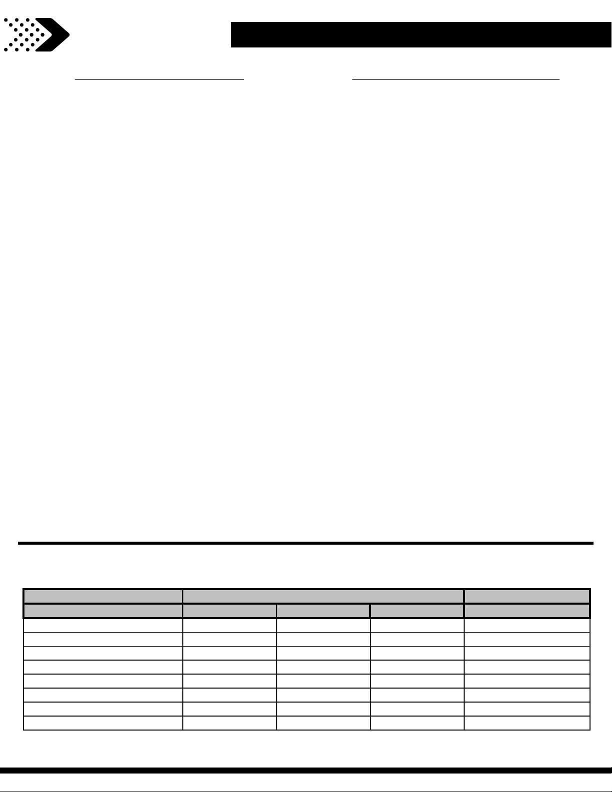
Material Compressed Depth
6" (152mm) 9" (228mm) 12" (304mm) to 9" (228mm)
Wood Chips
7' (2.13m) 10-12' (3.0-3.6m) 11' (3.35m) 10' (3.05m)
Double-Shredded Bark Mulch
6' (1.83m) 10-12' (3.0-3.6m) 11' (3.35m) 7' (2.13m)
Engineered Wood Fibers
6' (1.83m) 7' (2.13m) >12' (3.66m) 6' (1.83m)
Fine Sand
5' (1.52m) 5' (1.52m) 9' (2.74m) 5' (1.52m)
Coarse Sand
5' (1.52m) 5' (1.52m) 6' (1.83m) 4' (1.22m)
Fine Gravel
5' (1.52m) 7' (2.13m) 10' (3.05m) 6' (1.83m)
Medium Gravel
5' (1.52m) 5' (1.52m) 6' (1.83m) 5' (1.52m)
Shredded Tires*
10-12' (3.0-3.6m) N/A N/A N/A
Uncompressed Depth
Own
6
er’s Manual
Please Read This Before Starting Assembly
Positioning Your Playhouse
• The playhouse is designed to be installed on a
level surface by an Adult with an Adult helper.
Place in a fl at area of your yard to minimize
ground preparation.
• Choose a level location for the equipment. This
can reduce the likelihood of the playhouse
tipping over and loose-fi ll surfacing material
washing away during heavy rains.
• Place the equipment not less than 6'-7" (2.0 m)
from any structure or obstruction such as a
fence, garage, house, overhanging branches,
laundry lines, or electrical wires.
• It is a good idea to place your playhouse in
an area that is convenient for adults to watch
children at play.
• Create a site free of obstacles that could cause
injuries – such as low overhanging tree
branches, overhead wires, tree stumps and/or
roots, large rocks, bricks and concrete. We
have additional suggestions in the Suggested
Playground Surfacing Section.
• Do not build your playhouse on top of surfacing
material.
Suggested Playground Surfacing
• Do not install home playground equipment over
concrete, asphalt, packed earth, grass, carpet,
or any other hard surface. A fall onto a hard surface can result in serious injury to the equipment
user.
•
Do not install loose fi ll surfacing over hard
surfaces such as concrete or asphalt.
• Shredded bark mulch, wood chips, fi ne sand
and fi ne gravel, are added as shock absorbing
materials after assembly. If used properly these
materials can absorb some of the impact of a
child’s fall.
• All surface material should extend a minimum of
6 feet in all directions around the play area.
• Do not apply playground surfacing until after
the unit is completely constructed. Play house
should not be built on top of surfacing.
Use containment, such as digging out around
•
the perimeter and/or lining the perimeter with
landscape edging.
• Installations of rubber tiles or poured-inplace surfaces (other than loose-fi ll materials)
generally require a professional and are not “doit-yourself” projects.
• Shall use Playground Surfacing Materials
(other than loose-fi ll material) which comply
with the safety standard ASTM F1292 Standard
Specifi
Materials within the Use Zone of Playground
Equipment.
cation of Impact Attenuation of Surfacing
The following chart explains the fall height in feet from which a life threatening head injury would not be expected
Critical Heights in feet (m) of Tested Materials
*This data is from tests conducted by independent testing laboratories on a 6-inch depth of uncompressed shredded tire samples produced by four manufacturers. The tests reported
critical heights, which varied from 10 feet to greater than 12 feet. It is recommended that persons seeking to install shredded tires as a protective surface request test
data from the supplier showing the critical height of the material when it was tested in accordance with ASTM F1292.
Page 7

Own
7
er’s Manual
Please Read This Before Starting Assembly
APPENDIX A
The following information is from the United States
Consumer P
roduct Safety Commission’s Information
Sheet for playground surfacing material; also see
the following website for additional information:
www.cpsc.gov
X3. SECTION 4 OF THE CONSUMER PRODUCT SAFETY
COMMISSION’S
HANDBOOK
X3.1 Select Protective Surfacing—One of the most
important things you can do to reduce the likelihood of serious
head injuries is to install shock-absorbing protective surfacing
under and around your play equipment. The protective surfacing
should be applied to a depth that is suitable for the equipment
height in accordance with ASTM Speci cation F 1292. There are
di erent types of surfacing to choose from; whichever product
you select, follow these guidelines:
X3.1.1 Loose-Fill Materials:
X3.1.1.1 Maintain a minimum depth of 9 inches of loose! ll materials such as wood mulch/chips, engineered wood ! ber
(EWF), or shredded/recycled rubber mulch for equipment up to
8 feet high; and 9 inches of sand or pea gravel for equipment up
to 5 feet high. NOTE: An initial ! ll level of 12 inches will compress
to about a 9-inch depth of surfacing overtime. The surfacing will
also compact, displace, and settle, and should be periodically
re lled to maintain at least a 9-inch depth.
X3.1.2 Use a minimum of 6 inches of protective surfacing
for play equipment less than 4 feet in height. If maintained
properly, this should be adequate. (At depths less than 6 inches,
the protective material is too easily displaced or compacted.)
NOTE: Do not install home playground equipment over
concrete, asphalt, or any other hard surface. A fall onto a hard
surface can result in serious injury to the equipment user. Grass
and dirt are not considered protective surfacing because wear
and environmental factors can reduce their shock absorbing
e ectiveness. Carpeting and thin mats are generally not adequate
protective surfacing. Ground level equipment such as a sandbox,
activity wall, playhouse or other equipment that has no elevated
play surface – does not need any protective surfacing.
X3.1.3 Use containment, such as digging out around the
perimeter and/or lining the perimeter with landscape edging.
Don’t forget to account for water drainage.
X3.1.3.1 Check and maintain the depth of the loose! ll surfacing material. To maintain the right amount of loose- ll
materials, mark the correct level on play equipment support
posts. That way you can easily see when to replenish and/or
redistribute the surfacing.
OUTDOOR HOME PLAYGROUND SAFETY
9
X3.1.3.2 Do not install loose- ll surfacing over hard
surfaces such as concrete or asphalt.
X3.1.4 Poured-In-Place Surfaces or Pre-Manufactured
Rubber Tiles — You may be interested in using surfacing other
than loose- ll materials – like rubber tiles or poured-in-place
surfaces.
X3.1.4.1 Installations of these surfaces generally require
a professional and are not “do-it-yourself” projects.
X3.1.4.2 Review surface speci cation before purchasing
this type of surfacing. Ask the installer/manufacturer for a report
showing that the product has been tested to the following
safety standard: ASTM F 1292 Standard Speci cation for Impact
Attenuation of Surfacing Materials within the Use Zone of
Playground Equipment. This report should show the speci c
height for which the surface is intended to protect against serious
head injury. This height should be equal to or greater than the
fall height – vertical distance between a designated play surface
(elevated surface for standing, sitting, or climbing) and the
protective surfacing below – of your play equipment
X3.1.4.3 Check the protective surfacing frequently for
wear.
X3.1.5 Placement — Proper placement and maintenance
of protective surfacing is essential. Be sure to:
X3.1.5.1 Extend surfacing at least 6 feet from the
equipment in all directions.
X3.1.5.2 For to-fro swings, extend protective surfacing in
front of and behind the swing to a distance equal to twice the
height of the top bar from which the swing is suspended.
9
This information has been extracted from the CPSC
publications “P
“Handbook for Public Playground Safety.” Copies of these reports can
be obtained by sending a postcard to the: O$ ce of Public A" airs, U.S.
Consumer Product Safety Commission, Washington, D.C., 20207 or call
the toll-free hotline: 1-800-638-2772.
The American Society for Testing and Materials takes no position
respecting the validity of any parent right asserted in connection
with any item mentioned in this standard. Users of this standard are
expressly advised that determination of the validity of any such parent
rights, and the risk of infringement of such rights, are entirely their own
responsibility.
The standard is subject to revision at any time by the responsible
technical committee and must be reviewed every ! ve years and if not
revised, either approved or withdrawn. Your comments are invited either
for revision of this standard or for additional standards and should be
addressed to ASTM Headquarters. Your comments will receive careful
consideration at a meeting of the responsible technical committee, which
you may attend. If you feel that your comments have not received a fair
hearing you should make your views known to the ASTM Committee on
Standards. 100 Barr Harbor Drive, West Conshohocken, PA 19428.
layground Surfacing — Technical Information Guide” and
Page 8

Owne
8
r’s Manual
Instructions for Proper Maintenance
IT IS IMPORTANT TO CHECK AND TIGHTEN ALL HARDWARE AT THE BEGINNING AND DURING
THE SEASON AS THEY MAY LOOSEN DUE TO WOOD EXPANSION AND CONTRACTION.
At the beginning of each play season
• Tighten all har
• Lubricate all metallic moving parts per
manufacturer’s instructions.
• Check all protective coverings on bolts, pipes,
edges, and corners. Replace if they are loose,
cracked, or missing.
• Check all moving parts including swing seats,
ropes, cables, and chains for wear, rust, or other
deterioration. Replace as needed.
• Check metal parts for rust. If found, sand and
repaint using a non lead-based paint meeting the
requirements of 16 CFR 1303.
• Check all wood members for deterioration
and splinters. Sand down splinters and replace
deteriorating wood members.
• Reinstall any plastic parts, such as swing seats or any
other items that were removed for the cold season.
• Rake and check depth of loose ll protective
surfacing materials to prevent compaction and to
maintain appropriate depth. Replace as necessary.
dware.
Twice a month during play season
• Tighten all hardware.
• Check all protective coverings on bolts, pipes, edges, &
corners. Replace if they are loose, cracked, or missing.
• Rake and check depth of loose ll protective
surfacing materials to prevent compaction and to
maintain appropriate depth. Replace as necessary.
Additional Maintenance
• Check the swing beam and hardware every two
weeks due to wood expansion and contraction.
It is particularly important that this procedure be
followed at the beginning of each season.
• Inspect wood parts monthly. The grain of the wood
sometimes will lift in the dry season causing splinters
to appear. Light sand may be necessary to maintain
a safe playing environment. Treat your playset with
stain regularly, to help prevent severe checking/
splitting and other weather damage.
• A waterborne transparent stain has been applied to
your playset. This is done for color only. Once or twice
a year, depending on your climate conditions, you
must apply some type of protection (sealant) to the
wood of your unit. Prior to the application of sealant,
lightly sand any “rough” spots on your playset. Please
note this is a requirement of your warranty.
• Assembling and maintaining the playset on a level
location is very important. As your children play,
your playset will slowly dig its way into the soil, and
it is very important that it settles evenly. Make sure
the playset is level and true one each year or at the
beginning of each play season.
Disposal Instructions
When the Playcenter use is no longer desired, it should
be disassembled and disposed of in such a way that no
unreasonable hazards will exist at the time the unit is
discarded.
Once a month during play season.
• Lubricate all metallic moving parts per
manufacturer’s instructions.
• Check all moving parts including swing seats,
ropes, cables, and chains for wear, rust, or other
deterioration. Replace as needed.
At the end of each play season or when
the temperature drops below 32° F
• Remove plastic swing seats and other items as speci! ed
by the manufacturer and take indoors or do not use.
• Rake and check depth of loose ll protective
surfacing materials to prevent compaction and to
maintain appropriate depth. Replace as necessary.
Third Party Assembly
• Customer may, in their sole discretion, elect to use a
third party person or service to assemble this product.
Backyard Discovery assumes no responsibility or
liability for any charge incurred by the Customer for
any assembly services’. Please see our warranty for
more information about damaged and missing part
replacement coverage. Backyard Discovery will not
reimburse Customer for the price of parts purchased
• Modifi cations made by the consumer to the original
activity toy shall be carried out according to the
instructions of the manufacturer. In particular, instructions shall be provided with kit/accessory about the
installation of rope/nets concerning the minimum
diameter, the need for fi xation ends, overall length,
and positioning in relation to other at both structures.
OWNERS SHALL BE RESPONSIBLE FOR MAINTAINING THE LEGIBILITY OF THE WARNING LABELS
Page 9

Own
9
er’s Manual
Instructions for Proper Maintenance
Your Backyard Discovery structure is designed and constructed of quality
materials.
As with all outdoor products it will weather and wear. To maximize
the enjoyment, safety and life of your structure it is important that you properly
maintain it.
About Our Wood
Backyar
selecting the best quality lumber available, wood is still a product of nature and susceptible
to weathering which can change the appearance of your set.
What causes weathering? Does it a ect
the strength of my product?
One of the main reasons for weathering is the
e ects of water (moisture); the moisture content
of the wood at the surface is di erent than the
d Discovery uses 100% Cedar (C. Lanceolata) wood. Although we take great care in
How can I reduce the amount of
weathering t
1. Your wood product is coated with a
water-based stain. Sunlight will break down
the coating, so we recommend applying
o wood product?
interior of the wood. As the climate changes,
moisture moves in or out of the wood, causing
tension which can result in checking and or
warping. You can expect the following due to
weathering. These changes will not a ect the
strength of the product:
1. Checking is surface cracks in the wood along
the grain. A post (4” x 4”) will experience more
checking than a board (1” x 4”) because the surface
and interior moisture content will vary more widely
than in thinner wood.
2. Warping results from any distortion (twisting,
cupping) from the original plane of the board and
often happens from rapid wetting and drying of
the wood.
a water repellent or stain on a yearly basis
(see your local stain and paint supplier for a
recommended product). You must apply some
type of protection (sealant) to the wood of your
product. Please note this is a requirement
of your warranty. Most weathering is just
the normal result of nature and will not a ect
safety. However if you are concerned that a part
has experienced a severe weathering problem
please call our customer service department for
further assistance.
2. Inspect wood parts monthly. The grain of
the wood sometimes will lift in the dry season
causing splinters to appear. Light sanding may
be necessary to maintain a safe environment.
Treating your Product with protection (sealant)
after sanding will help prevent severe checking/
3. Fading happens as a natural change in the
wood color as it is exposed to sun-light and will
turn grey over time.
splitting and other weather damage.
Page 10
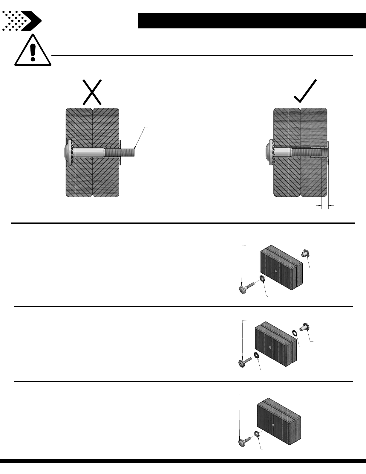
Protrusion Hazard
Proper Hardware Assembly
1/8”
CorrectIncorr
ect
Bolt and Barrel Nut Assembly
Insert barrel nut through the lock washer and press the pair
through the provided hole. Insert your bolt through the
second lock washer and insert the pair into the provided hole
opposite from the barrel nut. Turn clockwise to thread into the
barrel nut. Do not completely tighten until instructed.
LOCK WASHER
BOLT
BARREL NUT
Bolt and T-Nut Assembly
Tap T-nut into the provided hole. Insert your bolt through
the lock washer and insert into the provided hole opposite
from the T-Nut. Turn clockwise to thread into T-nut. Do not
completely tighten until instructed.
7187
LOCK WASHER
BOLT
Lag Assembly
Normally there will be a pre-drilled pilot hole on assemblies
that require a Lag Screw. If there is no pilot hole, line up the
two boards as they are to be attached and use the factory
drilled hole as a guide to drill another pilot hole into the
adjoining board. This will keep the wood from splitting. Only a
lock washer is required for steps with Lag Screws.
LOCK WASHER
LAG SCREW
If you see exposed
threads and your bolt
protrudes beyond the
T-Nut you may have over
tightened the bolt or
used incorrect hardware.
If you’ve overtightened,
remove the bolt and add
washers to eliminate the
protrusion.
Assembly Tips
Owner’s Manual
LOCK WASHER
10
Page 11
G2
G1
F2
F1
E1
E2
Ow
11
ner’s Manual
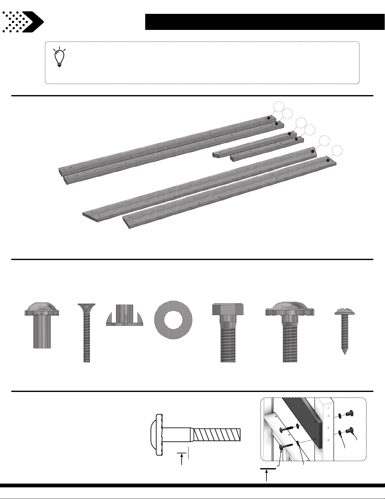
ASSEMBLY TIP:
Keep and ey
the assembly process as quick and painless as possible.
Assembly Tips
e out for these boxes which will contain helpful pictures and information making
Sorting Wood
When removing the wood from the boxes we recommend arranging them by part number before you begin
assembly. This will allow for faster assembly and easily identify any parts that may be missing or damaged.
Sor
ting Hardware
NUT BARREL
H100545
S
CREW
H100695
T-NUT
H100699
WASHER FLAT
H100706
BOLT HEX
H100716
BOLT
H100718
SCREW PWH
H100742
To help with assembly we recommend sorting your hardware bags with the seven digit alpha-numeric number
printed on the bags or by hardware type (i.e. bolts, nuts, etc.). Organizing your hardware will make assembly easier.
Hardware Identi cation
Hardware bags are printed with
a seven digit alpha-numeric part
number. During assembly you only
199
192
(x2)
need to reference the last three
digits of the part number as noted
in each step. This will make nding
the correct hardware easier.
H100378
(x2)
BOLT WH
5/
16 x 1-3/4
378
(x2)
198
(x2)
(x2)
Page 12
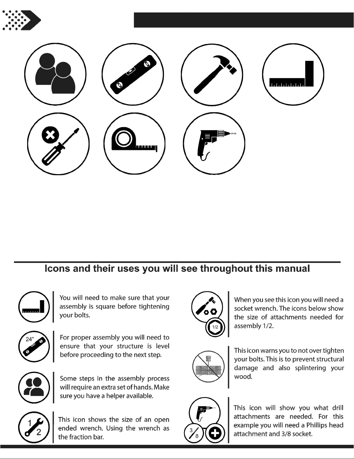
Owner's Manual
12
Tools Required for Installation
Page 13
Owner's Manual
13
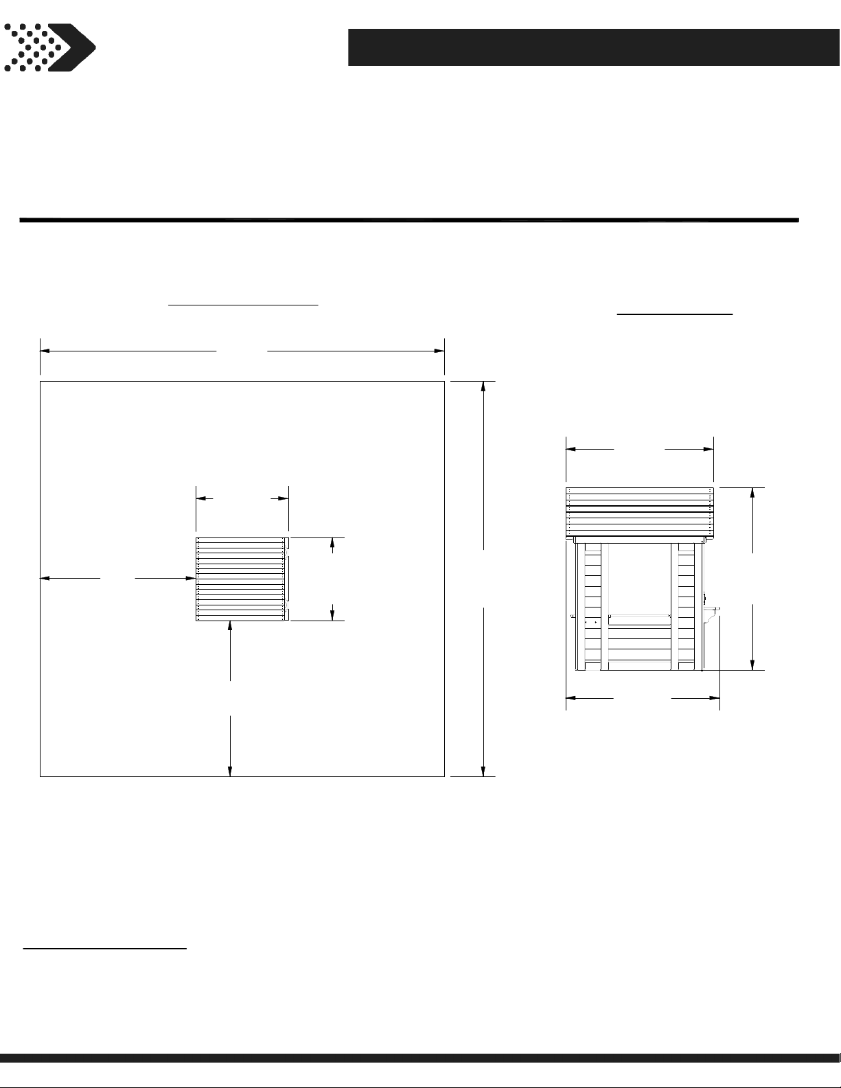
Basic Setup Dimensions & Assembly Notes
Selecting the correct location for your play product is important for your children’s
safety and the product’s longevity
• The safe play area refers to a zone extending 6'-7" (2m) beyond the play product on all sides, including the space
above the play product.
SAFE PLAY AREA DIAGRAM
Ground Dimension
3'-5 7/8" (1.1 m) x 3'-10 5/8" x (1.2 m) x 4' 7-3/8" (1.4 m)
17'- 5/8"
[5.2 m]
3'-10 5/8"
[1.2 m]
6'-7"
[2 m]
6'-7"
[2 m]
3'-5 7/8"
[1.1 m]
Safe Play Area
16'-7 7/8" (5.1 m) x 17'- 5/8" (5.2 m)
3'-8 7/8"
[1.1 m]
4'-7 3/8"
16'-7 7/8"
[5.1 m]
3'-10 5/8"
[1.2 m]
[1.4 m]
SAFE PLAY HEIGHT: 11'-2 3/8" [3.4 m]
MAXIMUM FALL HEIGHT: 4' 7-3/8" [1.4 m]
General Information:
Your set has been designed and engineered for children only and for residential use only.
A maximum of 150 lbs. per child is recommended for play activities designed for individual use.
A maximum of 120 lbs. per child is recommended for play activities designed for multiple child use.
A maximum of 9 children is recommended for this swing set.
Page 14
Owner's Manual
14
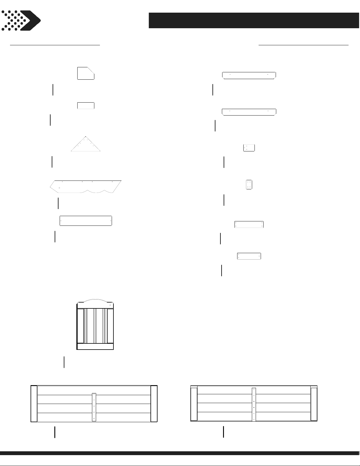
Wood Components (Not to Scale)
Parts Identification
COUNTER TOP SUPPORT - W4L13444
D1
1 3/8”x4 3/8”x5 7/8” (36x112x150)
(x1)
COUNTER TOP SUPPORT - W4L13445
J1
1”x2 3/8”x5 7/8” (24x60x150)
(x2)
TRIANGLE SUNBURST - W4L13450
K1
5/8”x5 1/4”x10 3/8” (16x134x265)
(x2)
GABLE BOARD - W4L13447
L1
5/8”x4 3/8”x25 3/8” (16x112x643)
(x4)
COUNTER TOP - W4L13446
M1
5/8”x3 3/8”x18 1/2” (16x86x469)
(x4)
SIDE WINDOW SHELF - W4L13453
N1
5/8”x2 3/8”x18 7/8” (16x60x479)
(x2)
REAR WINDOW SHELF - W4L13448
N2
5/8”x2 3/8”x19 1/8” (16x60x485)
(x1)
DOOR STOP - W4L13449
N3
5/8”x2 3/8”x3 7/8” (16x60x100)
(x1)
TIE STRAP - W4L13443
N4
5/8”x2”x3 1/8” (16x50x80)
(x8)
SUNBURST LEG - W4L13451
N5
5/8”x2 3/8”x10 1/4” (16x60x260)
(x2)
DOOR ASSEMBLY - W2A02980
DP1
1 1/4""x17 15/16""x13 1/8"" (32x456x334)
(x1)
LOWER ROOF PANEL - W2A02982
RP1
1 3/8"x13"x44 7/8" (35x329x1140)
(x2)
SUNBURST LEG - W4L13452
N6
5/8”x2 3/8”x8 1/4” (16x60x210)
(x4)
UPPER ROOF PANEL - W2A02983
RP2
1 3/8"x12 3/4"x44 7/8" (35x324x1140)
(x2)
Page 15
Owner's Manual
15
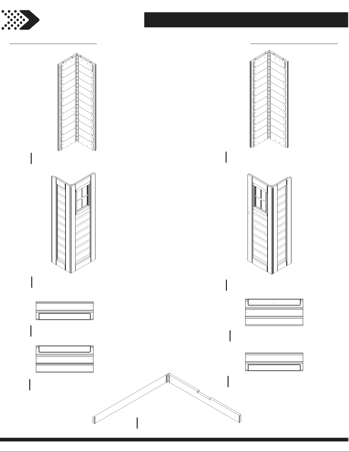
Wood Components (Not to Scale)
Parts Identification
WP3
(x1)
WP1
(x1)
LEFT REAR CORNER PANEL - W2A02993
LEFT FRONT CORNER PANEL - W2A02991
WP4
(x1)
WP2
(x1)
RIGHT REAR CORNER PANEL - W2A02994
RIGHT FRONT CORNER PANEL - W2A02992
WP5
WP6
LOWER CENTER WALL - W2A02978
1 1/2"x6 5/8"x20 7/8" (38x167x530)
(x2)
UPPER CENTER WALL - W2A02979
1 1/2"x9 3/4"x20 7/8"(38x248x530)
(x2)
WP9
(x2)
WP7
WP8
(x1)
HEADER ASSEMBLY - W2A02981
3 3/8"x37 7/8"x38 7/8" (86x962x986)
UPPER REAR CENTER WALL - W2A02989
1 1/2"x21 1/8"x9 3/4" (38x536x248)
(x1)
LOWER REAR CENTER WALL - W2A02990
1 1/2"x6 5/8"x21 1/8" (38x167x536)
Page 16
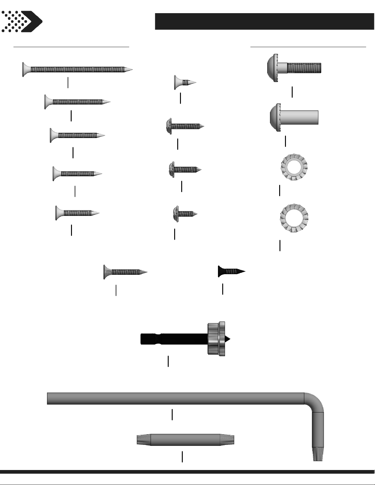
Owner's Manual Parts Identification
16
Hardware Components
H100090
(x7)
H100086
(x24)
H100087
(x57)
H100088
(x33)
H100085
(x41)
SCREW PFH
8x2 1/2"
SCREW PFH
8x1 1/2
SCREW PFH
8x1 1/4
SCREW PFH
8x1 1/8
SCREW PFH
8x1
H100124
(x2)
H100070
(x9)
H100128
(x4)
H100361
(x2)
SCREW PFH
8 x 1/2
SCREW PWH
8x3/4
SCREW PWH
8x5/8
SCREW PWH BLK
8x7/16
H100137
(x5)
H100140
(x5)
H100138
(x5)
H100139
(x5)
BOLT WH
1/4x1
NUT BARREL WH
1/4x7/8
WASHER LOCK EXT
6x15
WASHER LOCK EXT
8x15
H100537
(x2)
SCREW PFH SD
8x1
H100764
(x1)
H100114
(x2)
SCREW SETTER
TORX WRENCH
T-30
H100147
(x2)
TORX BIT
T-30
H100624
(x2)
SCREW PFH BLK
6x5/8
Page 17
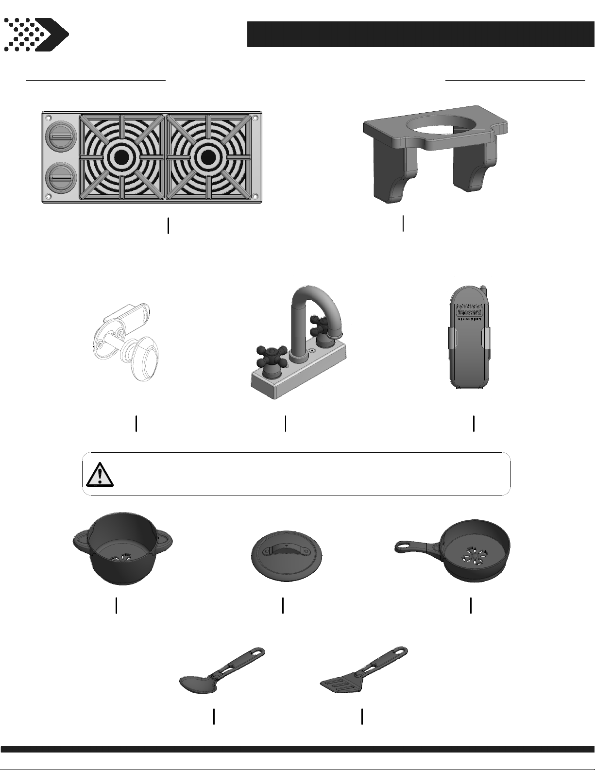
Owner's Manual
17
Accessory Components (Not to Scale)
Parts Identification
A6P00025
A6P00020
(x1)
(x1)
KNOB KIT
STOVE KIT
A6P00024
(x1)
FAUCET KIT
A6P00387
(x2)
FLOWER POT HOLDER - BLK
A100132
(x1)
BE SURE TO WASH ALL PLASTIC TOYS BEFORE USE.
PHONE KIT
A6P00338
(x1)
FRY PAN
LADLE
A6P00337
(x1)
POT/PAN LID
A6P00339
(x1)
SPATULA
A6P00336
(x1)
BOIL POT
A6P00340
(x1)
Page 18
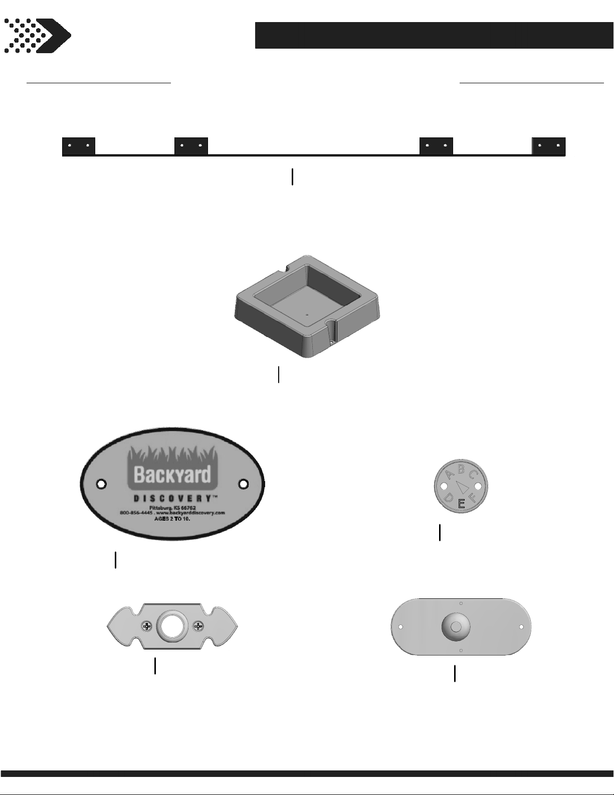
Owner's Manual
18
Accessory Components (Not to Scale)
Parts Identification
A4M00517
(x1)
A6P00032
(x1)
METAL TIE STRAP
SURFACE MOUNT BASIN
A100314
(x1)
A4M00528
(x1)
BYD ID TAG (MEDIUM) AGES 2 TO 10
A6P00290
(x1)
DOOR BELL PLATE
"A" REVISION TAG
A100174
(x1)
DOOR BELL
Page 19
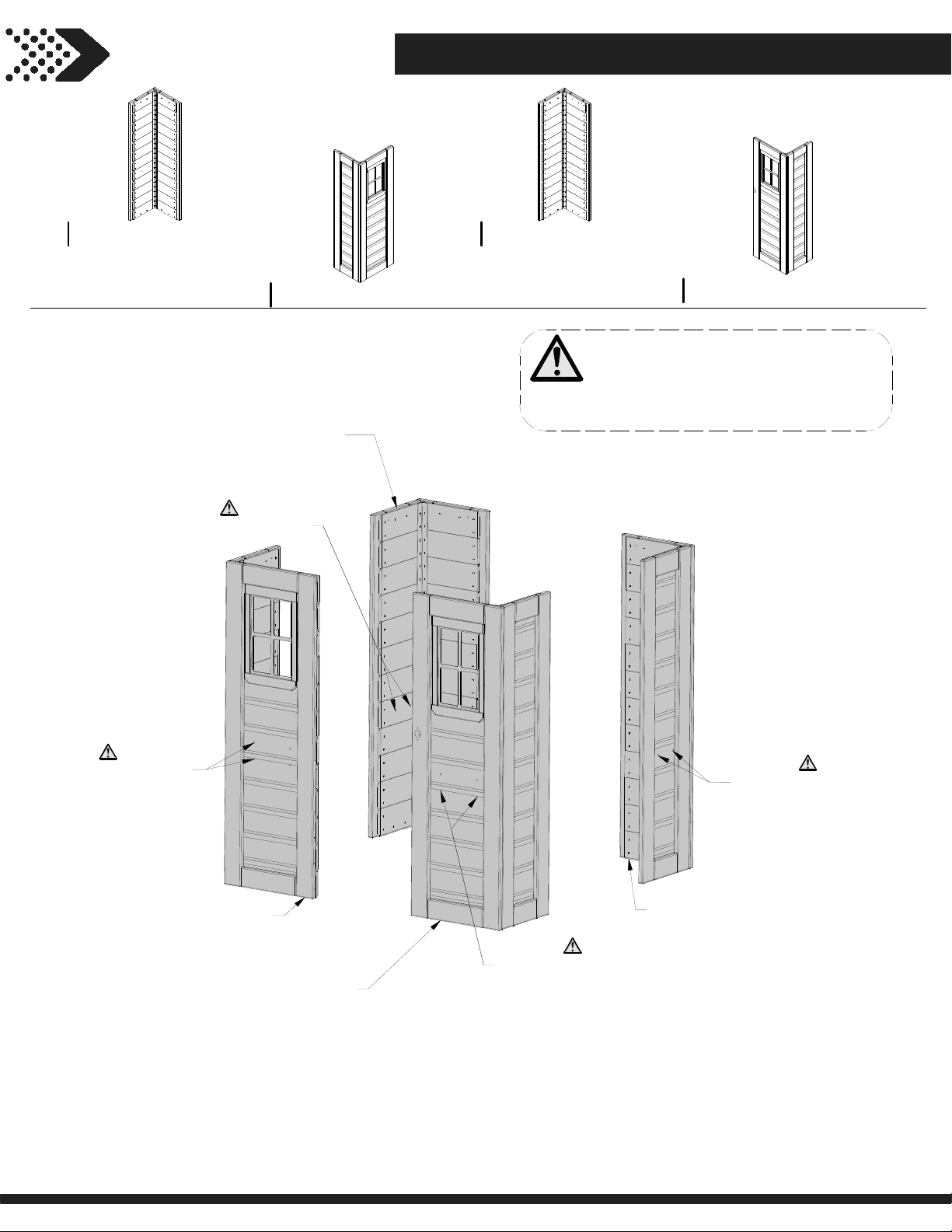
STEP 1
19
WP3
LEFT REAR CORNER PANEL - W2A02993
(x1)
LEFT REAR CORNER PANEL
NOTE HOLE LOCATIONS
WP1
LEFT FRONT CORNER PANEL - W2A02991
(x1)
WP3
(x1)
WP4
RIGHT REAR CORNER PANEL - W2A02994
(x1)
NOTE:
POSITION WALL PANELS AS SHOWN
BELOW. VERIFY THE CORRECT PANEL
PLACEMENT BY CHECKING THE HOLE
LOCATIONS AS SHOWN BELOW.
WP2
RIGHT FRONT CORNER PANEL - W2A02992
(x1)
NOTE HOLE LOCATIONS
LEFT FRONT CORNER PANEL
RIGHT FRONT CORNER PANEL
WP1
(x1)
WP2
(x1)
NOTE HOLE LOCATIONS
NOTE HOLE LOCATIONS
WP4
(x1)
RIGHT REAR CORNER PANEL
Page 20
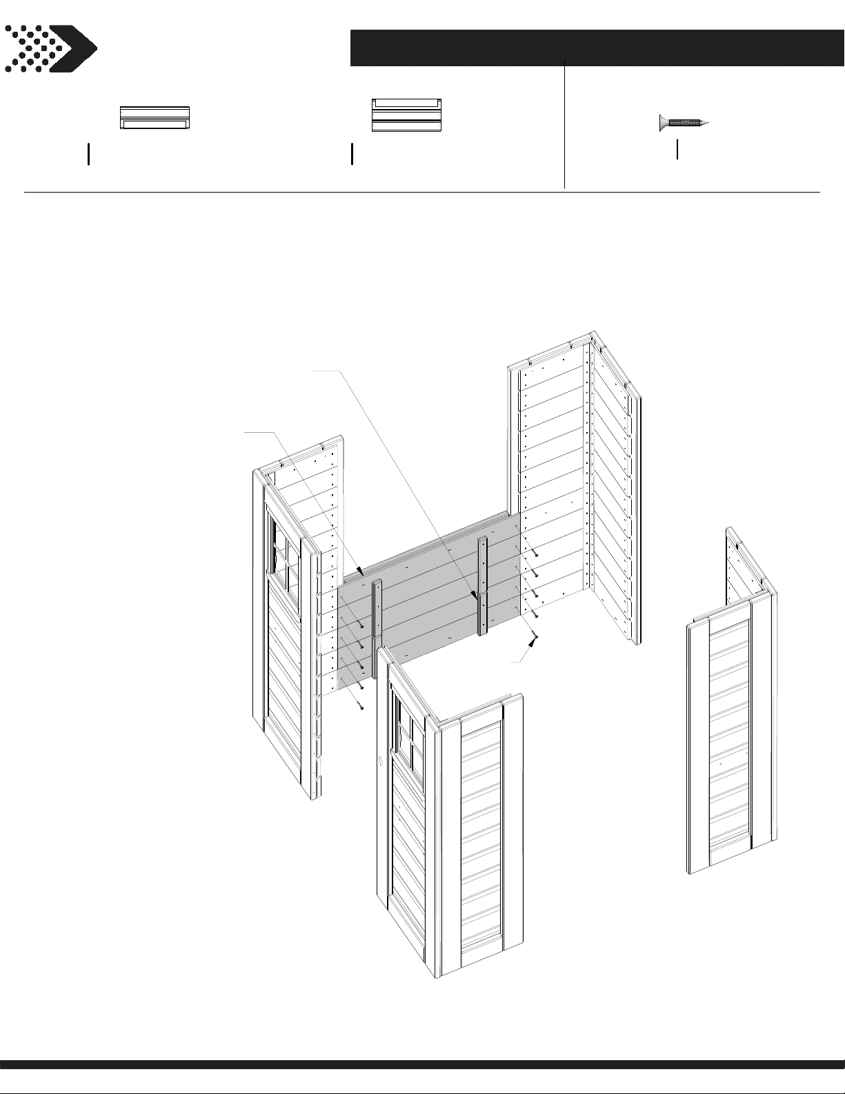
STEP 2
20
LOWER CENTER WALL - W2A02978
WP5
1 1/2"x6 5/8"x20 7/8" (38x167x530)
(x1)
LOWER CENTER WALL
WP6
UPPER CENTER WALL
(x1)
WP5
(x1)
UPPER CENTER WALL - W2A02979
WP6
1 1/2"x9 3/4"x20 7/8"(38x248x530)
(x1)
H100085
(x10)
SCREW PFH
8x1
085
(x10)
SCREW - 1"
Page 21
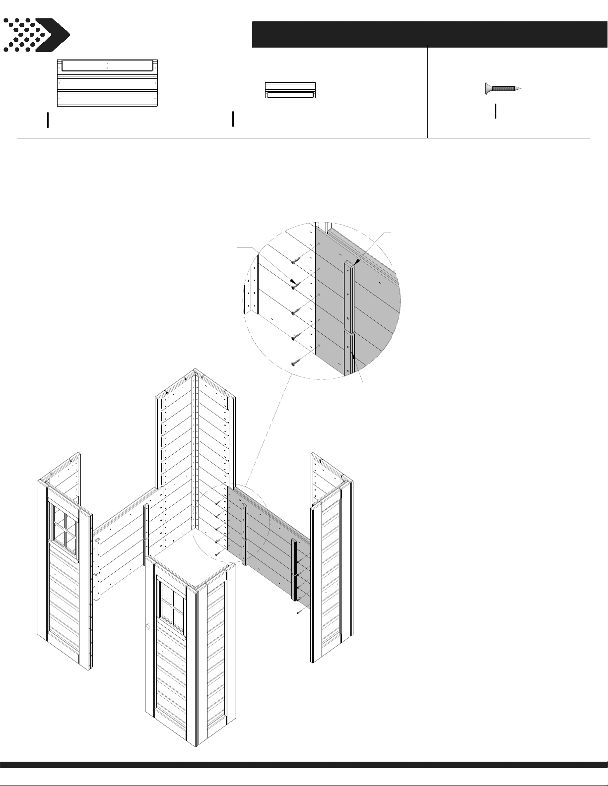
STEP 3
21
UPPER REAR CENTER WALL - W2A02989
WP7
1 1/2"x21 1/8"x9 3/4" (38x536x248)
(x1)
WP8
(x1)
085
(x10)
SCREW - 1"
LOWER REAR CENTER WALL - W2A02990
1 1/2"x6 5/8"x21 1/8" (38x167x536)
WP8
LOWER REAR CENTER WALL
WP7
(x1)
H100085
(x10)
SCREW PFH
8x1
UPPER REAR CENTER WALL
(x1)
Page 22
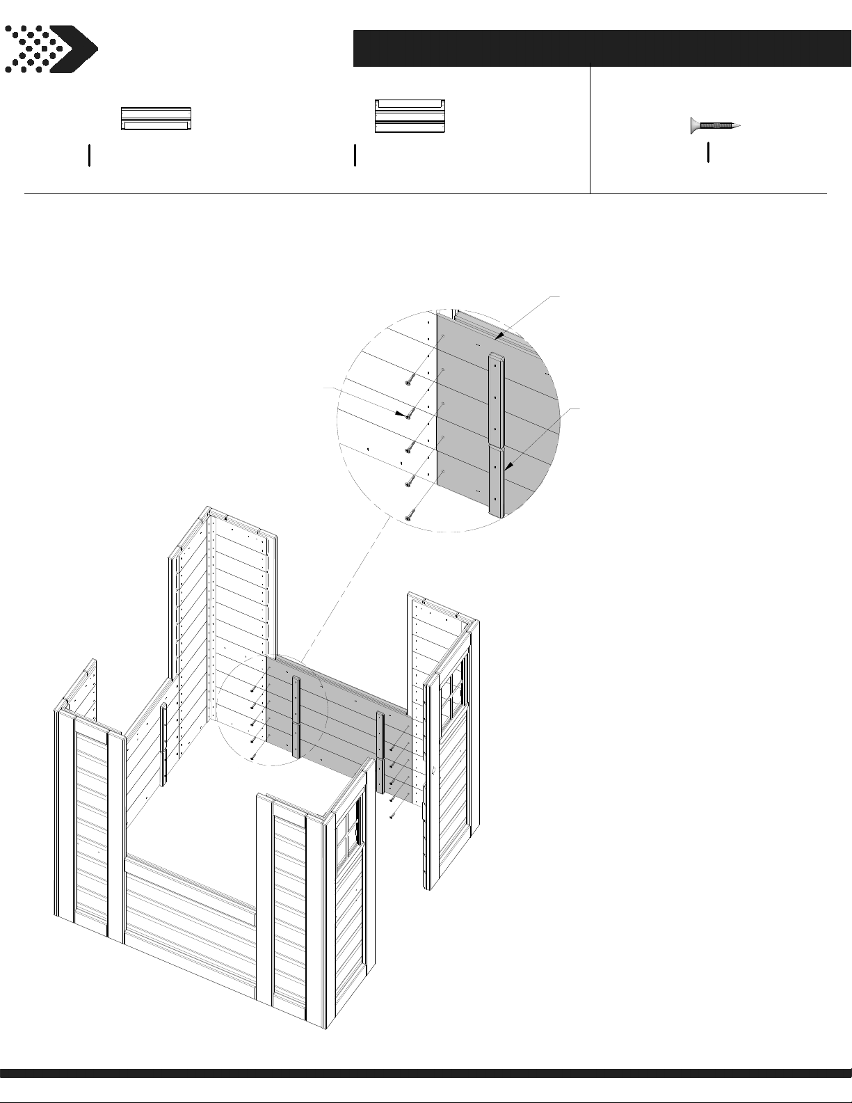
STEP 4
22
LOWER CENTER WALL - W2A02978
WP5
1 1/2"x6 5/8"x20 7/8" (38x167x530)
(x1)
085
(x10)
SCREW - 1"
UPPER CENTER WALL - W2A02979
WP6
1 1/2"x9 3/4"x20 7/8"(38x248x530)
(x1)
H100085
(x10)
WP6
(x1)
UPPER CENTER WALL
WP5
(x1)
LOWER CENTER WALL
SCREW PFH
8x1
Page 23
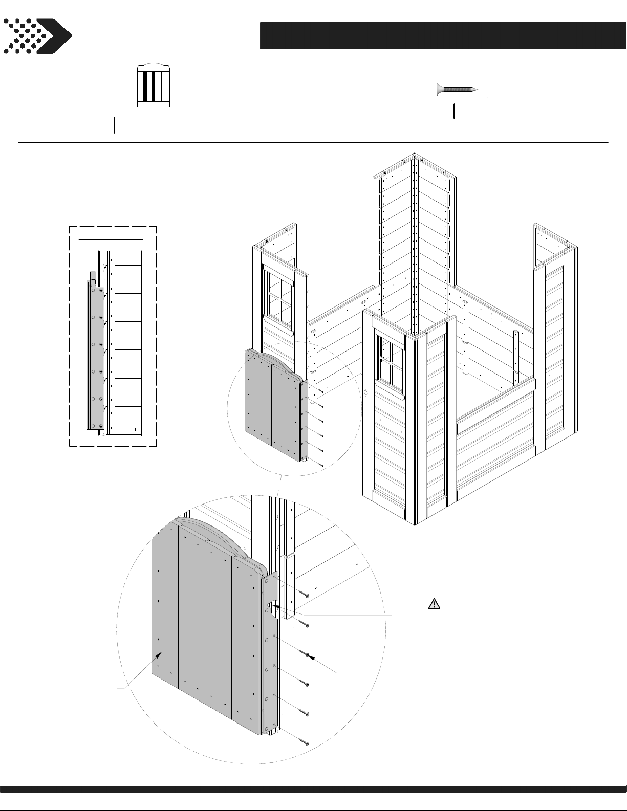
STEP 5
23
DOOR ASSEMBLY - W2A02980
DP1
1 1/4""x17 15/16""x13 1/8"" (32x456x334)
(x1)
SIDE VIEW
H100088
(x6)
SCREW PFH
8x1 1/8
DP1
(x1)
DOOR ASSEMBLY
NOTE PILOT HOLES
088
(x6)
SCREW - 1 1/8"
Page 24
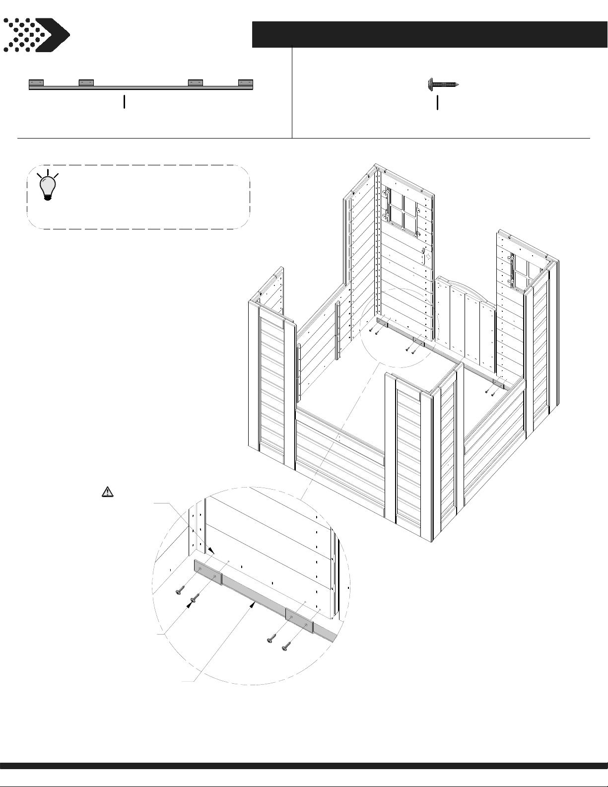
STEP 6
24
A4M00517
(x1)
METAL TIE STRAP
TIP:
ALIGN TIE STRAP WITH PILOT
HOLES AND ASSEMBLE AS
SHOWN.
H100070
(x8)
SCREW PWH
8x3/4
NOTE PILOT HOLES
070
(x8)
SCREW - 8x3/4"
517
(x1)
METAL TIE STRAP
Page 25
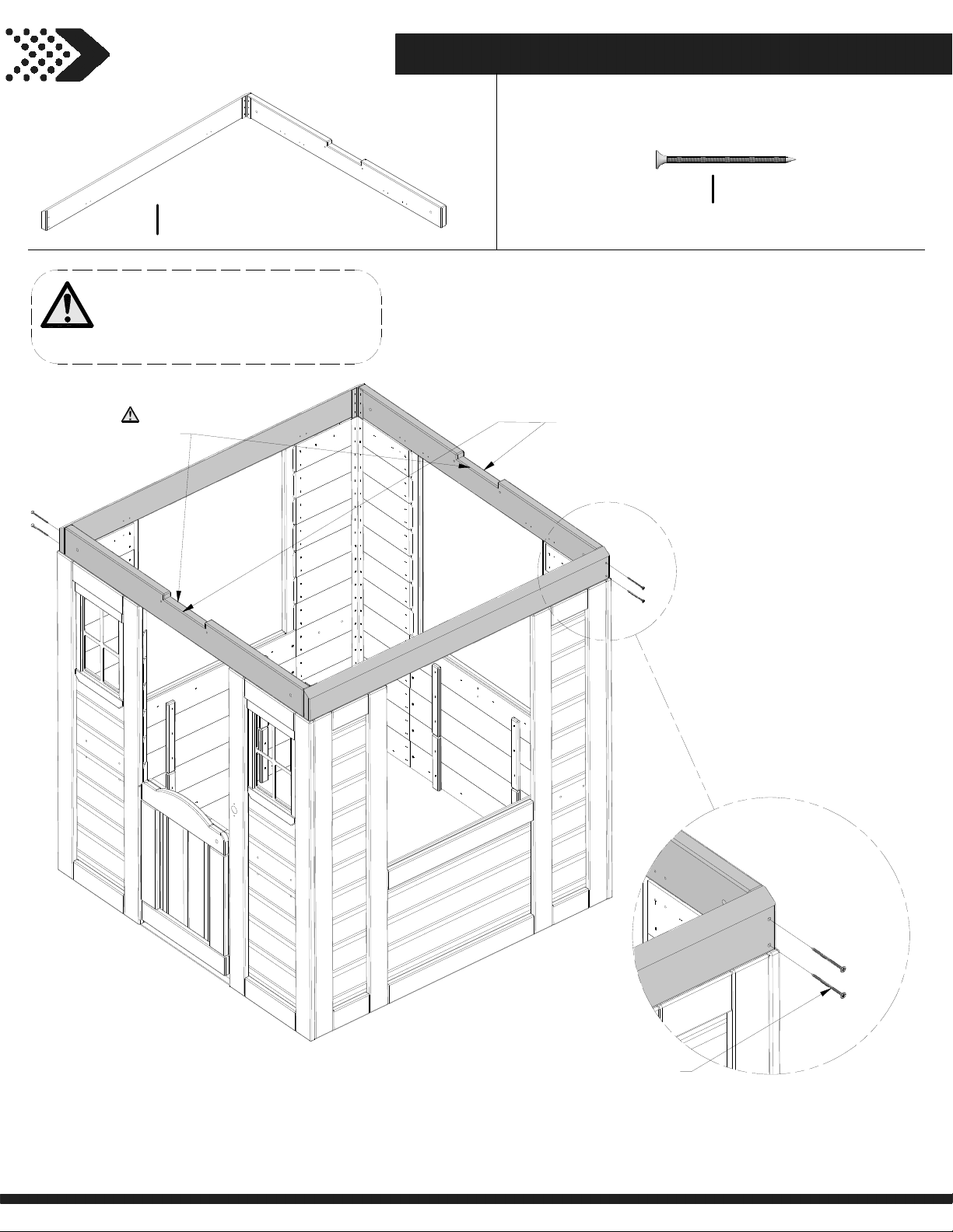
STEP 7
25
WP9
HEADER ASSEMBLY - W2A02981
3 3/8"x37 7/8"x38 7/8" (86x962x986)
(x2)
NOTE:
REST HEADER ASSEMBLIES ON
THE WALL PANELS AND ASSEMBLY
AS SHOWN.
NOTE NOTCH
LOCATION.
H100090
(x4)
WP9
(x2)
HEADER ASSEMBLY
SCREW PFH
8x2 1/2"
090
(x4)
SCREW - 2 1/2"
Page 26
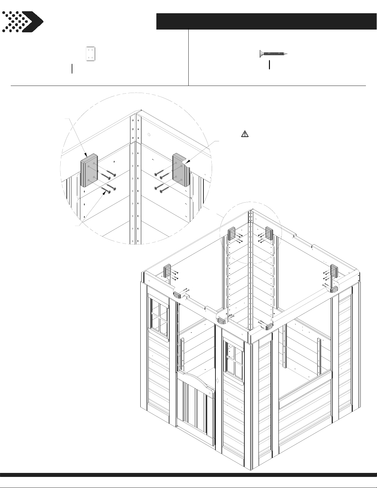
STEP 8
26
N4
(x8)
N4
(x8)
TIE STRAP
087
(x32)
SCREW - 1-1/4"
TIE STRAP - W4L13443
5/8”x2”x3 1/8” (16x50x80)
H100087
(x32)
NOTE PILOT HOLES
SCREW PFH
8x1 1/4
Page 27
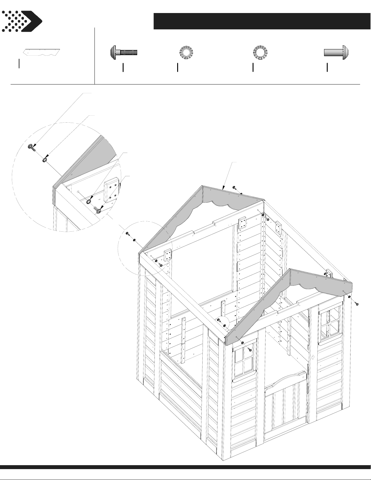
GABLE BOARD - W4L13447
27
L1
5/8”x4 3/8”x25 3/8” (16x112x643)
(x4)
STEP 9
H100137
(x4)
137
(x4)
BOLT WH - 1"
138
(x4)
WASHER - 6x15
(x4)
H100138
(x4)
BOLT WH
1/4x1
139
WASHER - 8x15
140
(x4)
NUT BARREL - 7/8
WASHER LOCK EXT
6x15
H100139
WASHER LOCK EXT
(x4)
8x15
L1
(x4)
GABLE BOARD
H100140
(x4)
NUT BARREL WH
1/4x7/8
Page 28
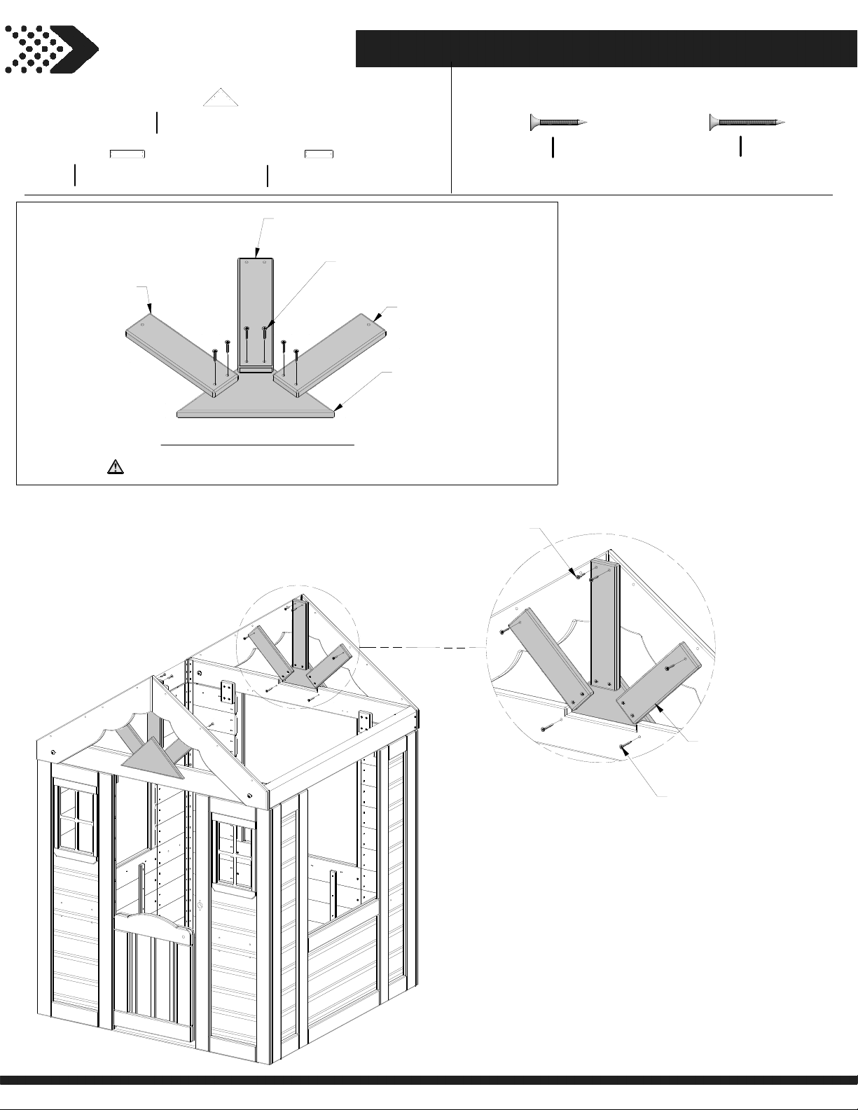
SUNBURST LEG - W4L13451
28
N5
5/8”x2 3/8”x10 1/4” (16x60x260)
(x2)
N6
(x1)
SUNBURST LEG
STEP 10
TRIANGLE SUNBURST - W4L13450
K1
5/8”x5 1/4”x10 3/8” (16x134x265)
(x2)
SUNBURST LEG - W4L13452
N6
5/8”x2 3/8”x8 1/4” (16x60x210)
(x4)
N5
SUNBURST LEG
SUNBURST ASSEMBLY
NOTE:
REPEAT STEP TO COMPLETE
TWO SUNBURST ASSEMBLIES.
(x1)
088
SCREW - 1 1/8"
(x6)
N6
(x1)
SUNBURST LEG
K1
(x1)
TRIANGLE SUNBURST
H100088
(x20)
SCREW PFH
8x1 1/8
H100086
(x4)
SCREW PFH
8x1 1/2
088
(x8)
SCREW - 1 1/8"
SUNBURST ASSEMBLY
FROM ABOVE.
086
(x4)
SCREW - 1 1/2"
Page 29
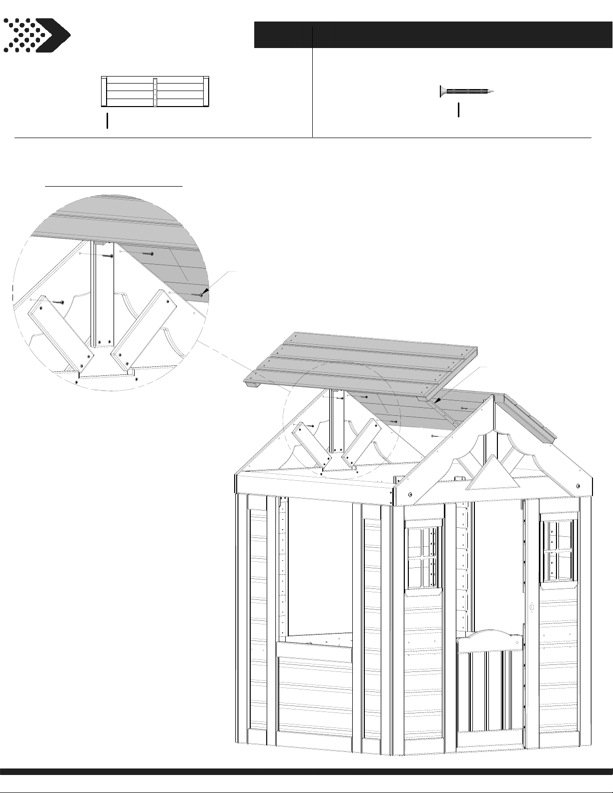
STEP 11
29
UPPER ROOF PANEL - W2A02983
RP2
1 3/8"x12 3/4"x44 7/8" (35x324x1140)
(x2)
REPEAT ON OPPOSITE END
086
(x4)
SCREW - 1 1/2"
H100086
(x8)
SCREW PFH
8x1 1/2
RP2
(x2)
UPPER ROOF PANEL
Page 30
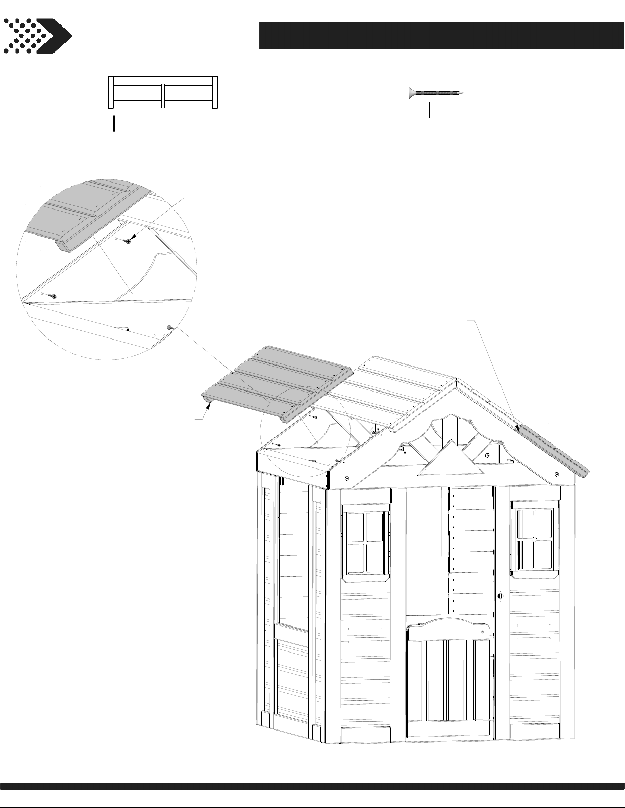
STEP 12
30
LOWER ROOF PANEL - W2A02982
RP1
1 3/8"x13"x44 7/8" (35x329x1140)
(x2)
REPEAT ON OPPOSITE END
086
(x4)
SCREW - 1 1/2"
H100086
(x8)
SCREW PFH
8x1 1/2
RP1
(x1)
LOWER ROOF PANEL
RP1
(x1)
LOWER ROOF PANEL
Page 31
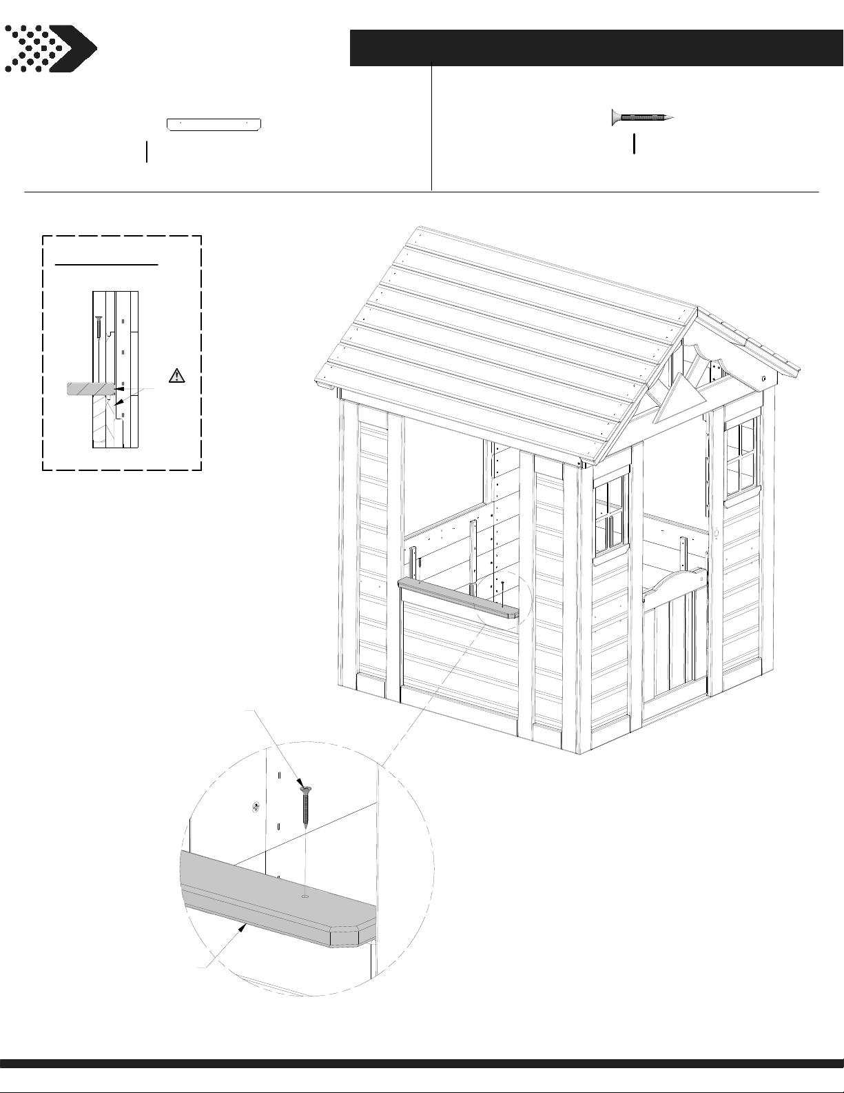
STEP 13
31
N1
(x1)
INSIDE VIEW
SIDE WINDOW SHELF - W4L13453
5/8”x2 3/8”x18 7/8” (16x60x479)
FLUSH
H100087
(x2)
SCREW PFH
8x1 1/4
SCREW - 1-1/4"
N1
(x1)
SIDE WINDOW SHELF
087
(x2)
Page 32
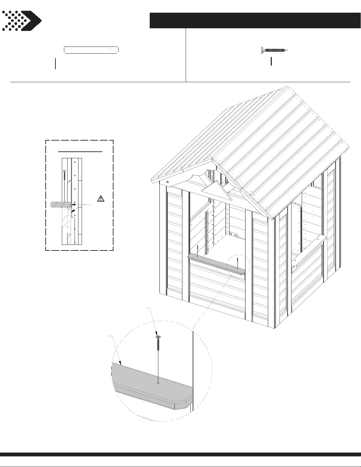
STEP 14
32
REAR WINDOW SHELF - W4L13448
N2
5/8”x2 3/8”x19 1/8” (16x60x485)
(x1)
INSIDE VIEW
FLUSH
H100087
(x2)
SCREW PFH
8x1 1/4
SCREW - 1-1/4"
N2
(x1)
REAR WINDOW SHELF
087
(x2)
Page 33
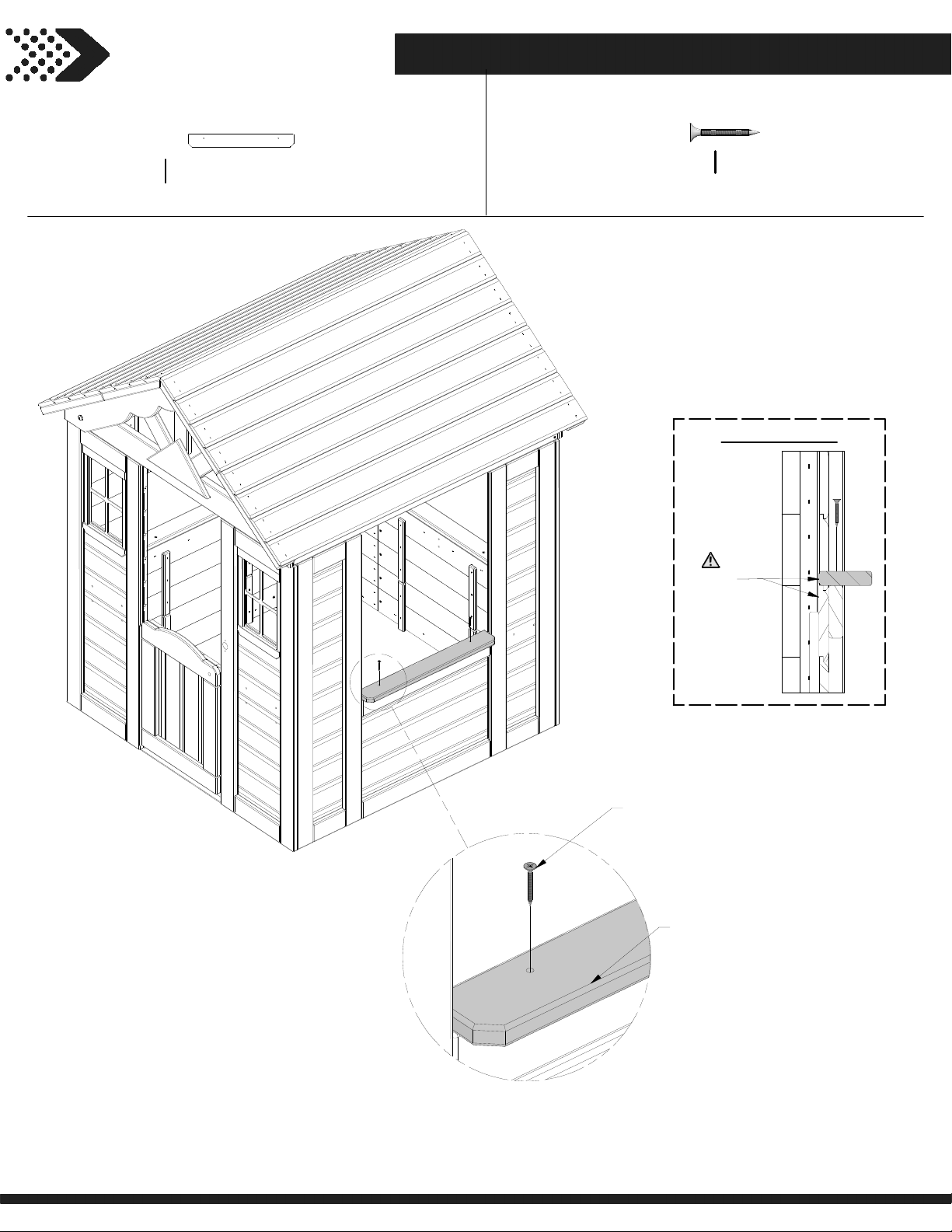
STEP 15
33
SIDE WINDOW SHELF - W4L13453
N1
5/8”x2 3/8”x18 7/8” (16x60x479)
(x1)
H100087
(x2)
FLUSH
SCREW PFH
8x1 1/4
INSIDE VIEW
087
(x2)
SCREW - 1-1/4"
N1
(x1)
SIDE WINDOW SHELF
Page 34
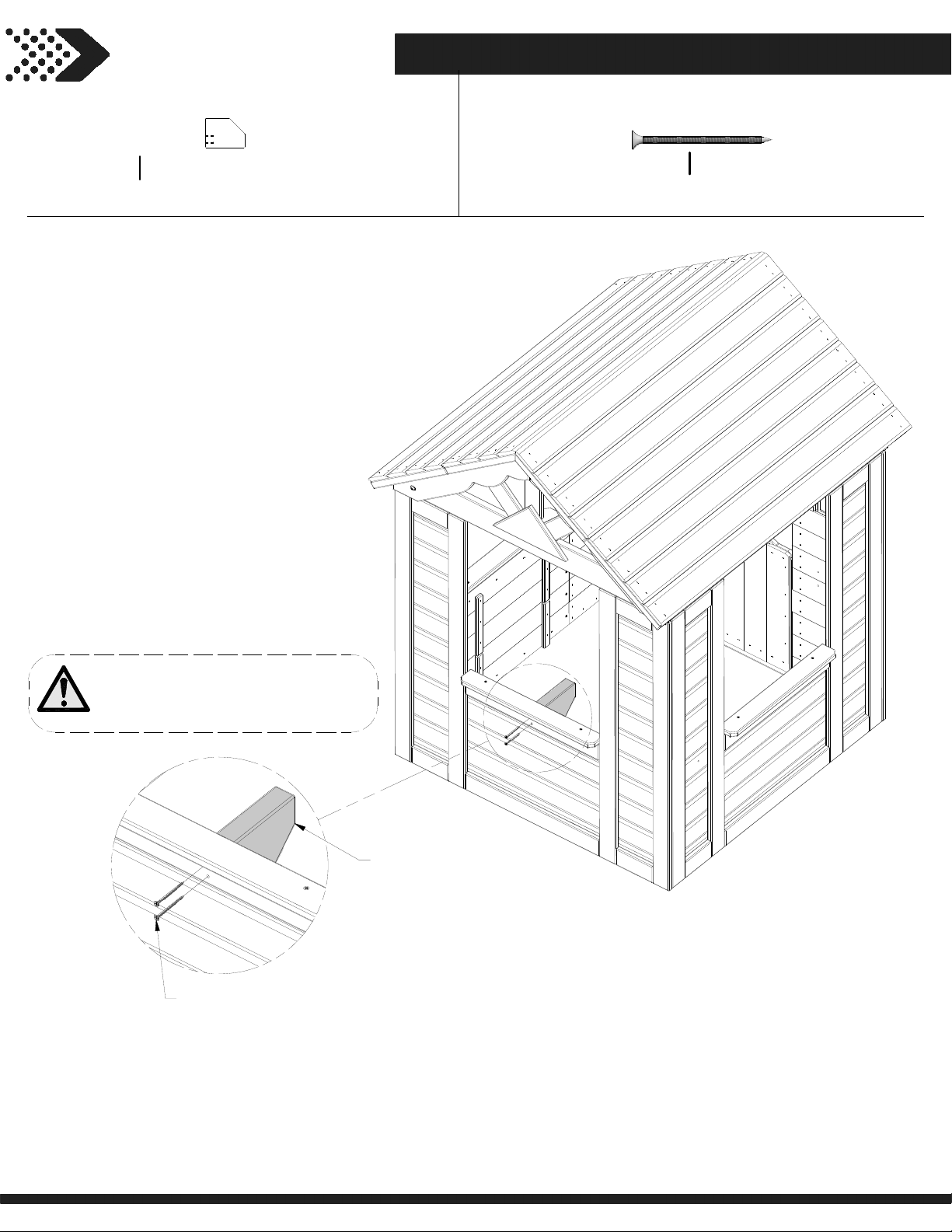
STEP 16
34
COUNTER TOP SUPPORT - W4L13444
D1
1 3/8”x4 3/8”x5 7/8” (36x112x150)
(x1)
H100090
(x2)
SCREW PFH
8x2 1/2"
NOTE:
ALIGN PILOT HOLES IN D1 AND
ASSEMBLE.
090
(x2)
SCREW - 2 1/2"
D1
(x1)
COUNTER TOP SUPPORT
Page 35
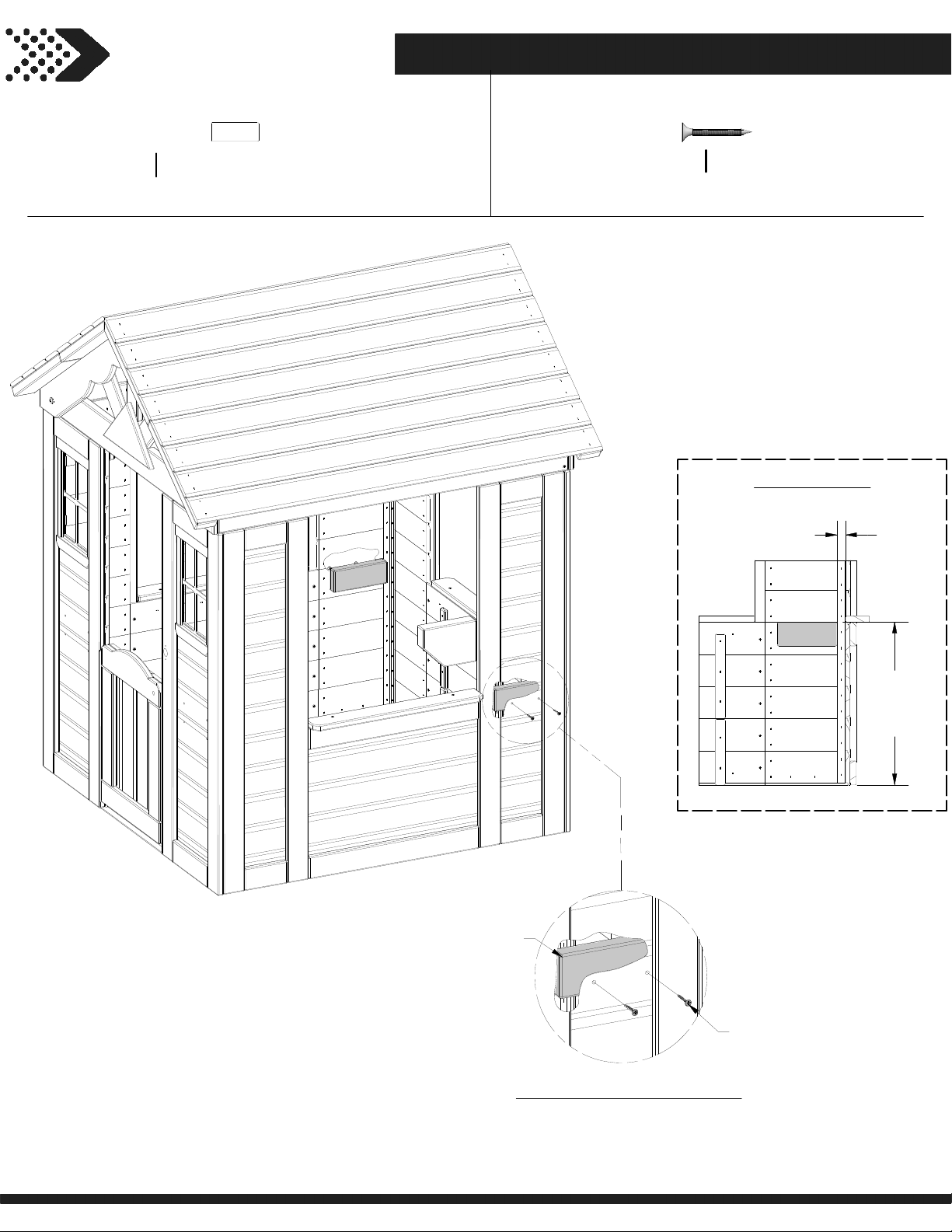
STEP 17
35
COUNTER TOP SUPPORT - W4L13445
J1
1”x2 3/8”x5 7/8” (24x60x150)
(x2)
H100087
(x4)
SCREW PFH
8x1 1/4
INSIDE VIEW
7/8 in
[22 mm]
J1
(x1)
COUNTER TOP SUPPORT
REPEAT ON OPPOSITE WALL
087
(x2)
SCREW - 1-1/4"
16 1/8 in
[410 mm]
Page 36
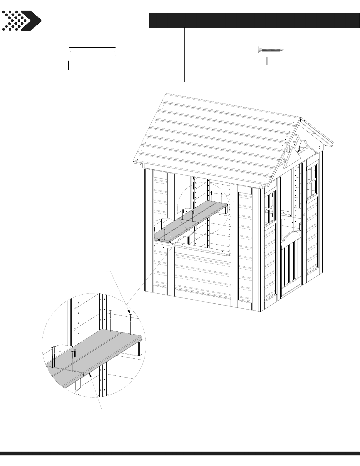
STEP 18
36
COUNTER TOP - W4L13446
M1
5/8”x3 3/8”x18 1/2” (16x86x469)
(x4)
H100087
(x8)
SCREW PFH
8x1 1/4
087
(x8)
SCREW - 1-1/4"
M1
(x4)
COUNTER TOP
Page 37
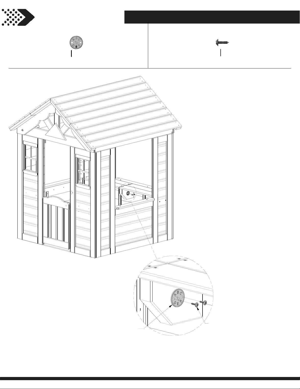
STEP 19
37
A100314
(x1)
"A" REVISION TAG
H100128
(x2)
SCREW PWH
8x5/8
314
(x1)
"A" REVISION TAG
128
(x2)
SCREW - 5/8
MOUNT IN THE APPROXIMATE
LOCATION SHOWN ABOVE.
Page 38
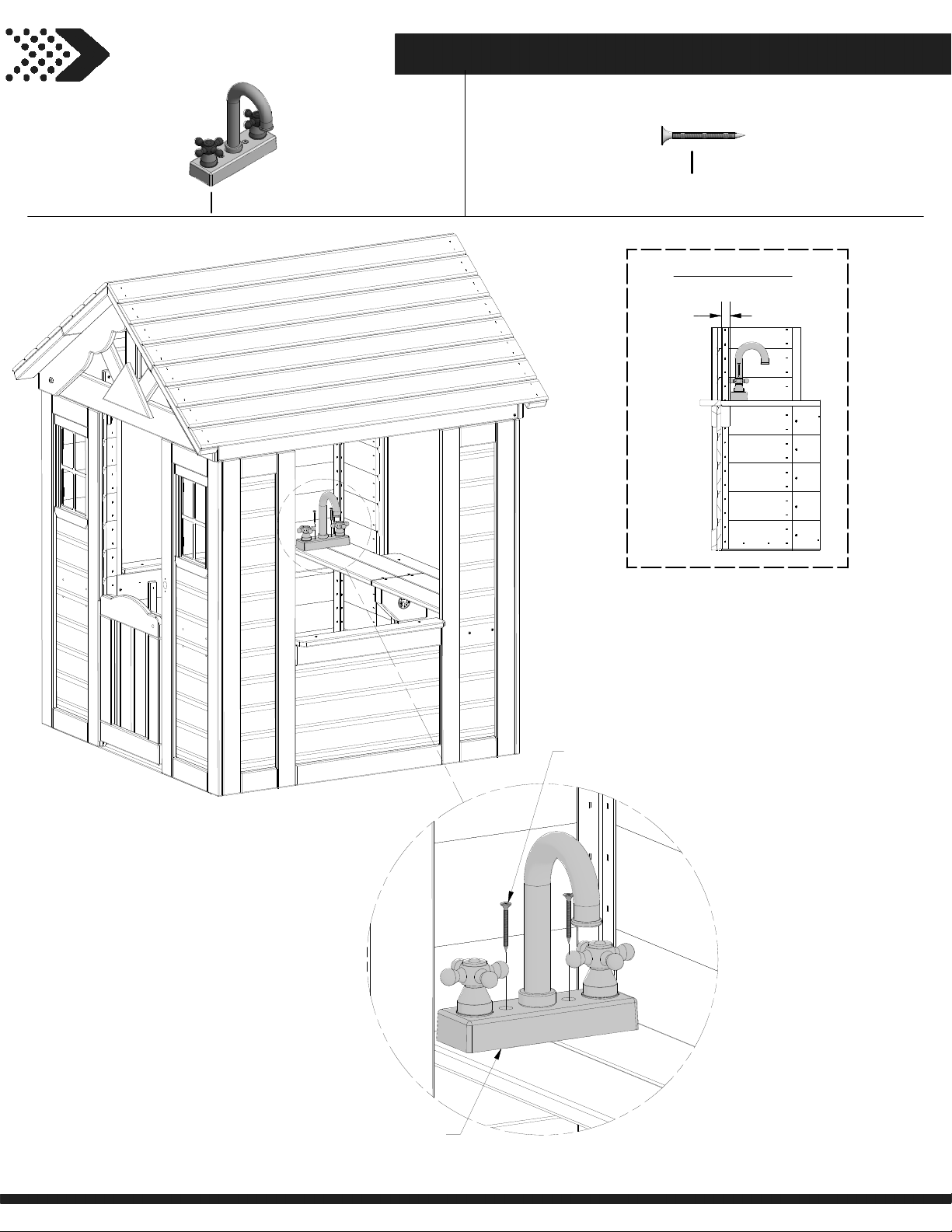
STEP 20
38
A6P00024
(x1)
FAUCET KIT
H100086
(x2)
SCREW PFH
8x1 1/2
FRONT VIEW
1 in
[25 mm]
024
(x1)
FAUCET KIT
086
(x2)
SCREW - 1 1/2"
Page 39
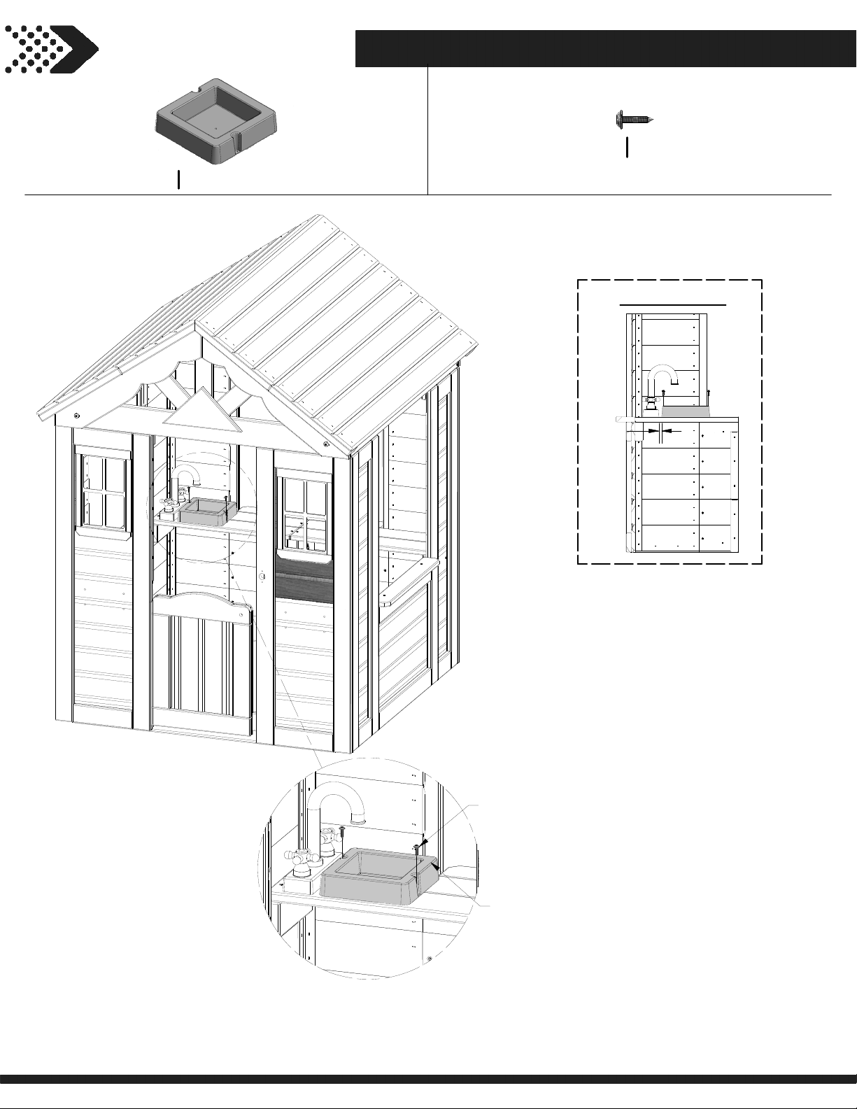
STEP 21
39
A6P00032
(x1)
SURFACE MOUNT BASIN
H100128
(x2)
SCREW PWH
8x5/8
FRONT VIEW
3/8 in
[9 mm]
128
(x2)
SCREW - 5/8
032
(x1)
SURFACE MOUNT BASIN
Page 40
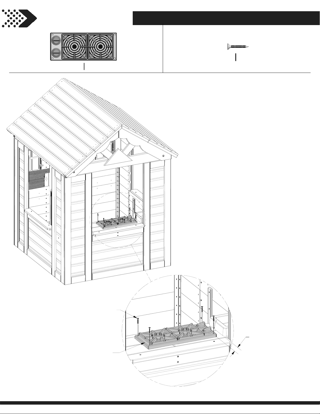
STEP 22
40
A6P00025
(x1)
STOVE KIT
H100088
(x4)
SCREW PFH
8x1 1/8
088
(x4)
SCREW - 1 1/8"
025
(x1)
STOVE KIT
1 1/8 in
[29 mm]
Page 41
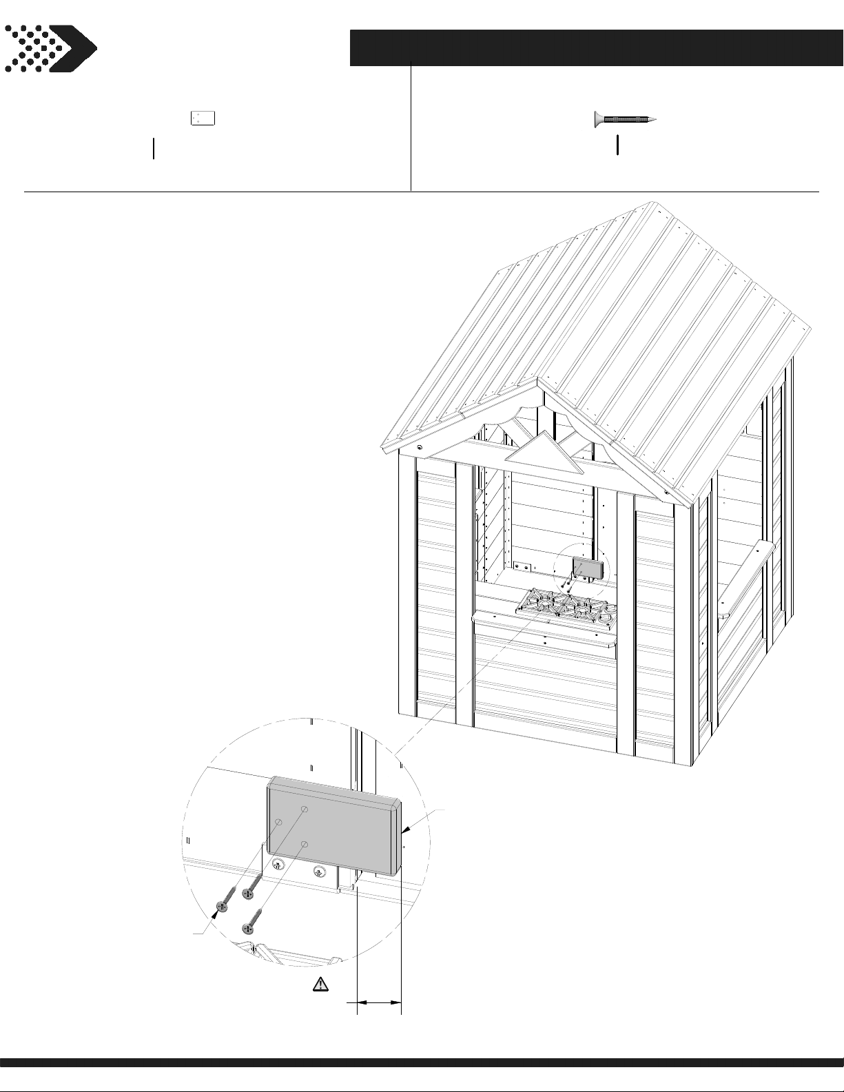
STEP 23
41
DOOR STOP - W4L13449
N3
5/8”x2 3/8”x3 7/8” (16x60x100)
(x1)
H100087
(x3)
SCREW PFH
8x1 1/4
087
(x3)
SCREW - 1-1/4"
1 5/8 in
[40 mm]
N3
(x1)
DOOR STOP
Page 42
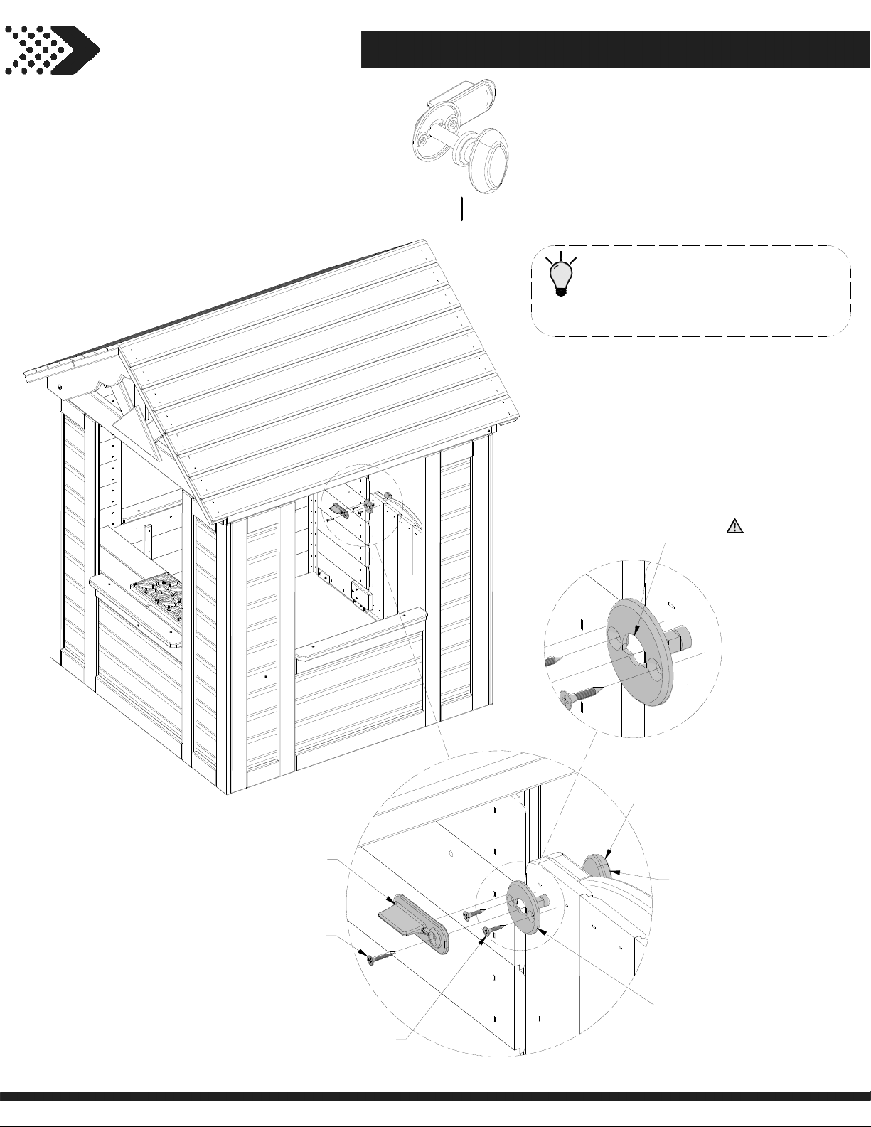
STEP 24
42
A6P00020
(x1)
KNOB KIT
TIP:
WHEN DOOR LATCH IS IN THE
UNLOCKED POSITION IT SHOULD
FACE IN THE UPWARD DIRECTION.
NOTE ARCH IN FACE
PLATE FACES UP.
020
(x1)
LATCHING KNOB KIT
LATCH
KNOB
SCREW - 1"
(x1)
INCLUDED IN KNOB KIT
FACE PLATE
SCREW - 3/4"
INCLUDED IN KNOB KIT
(x2)
Page 43
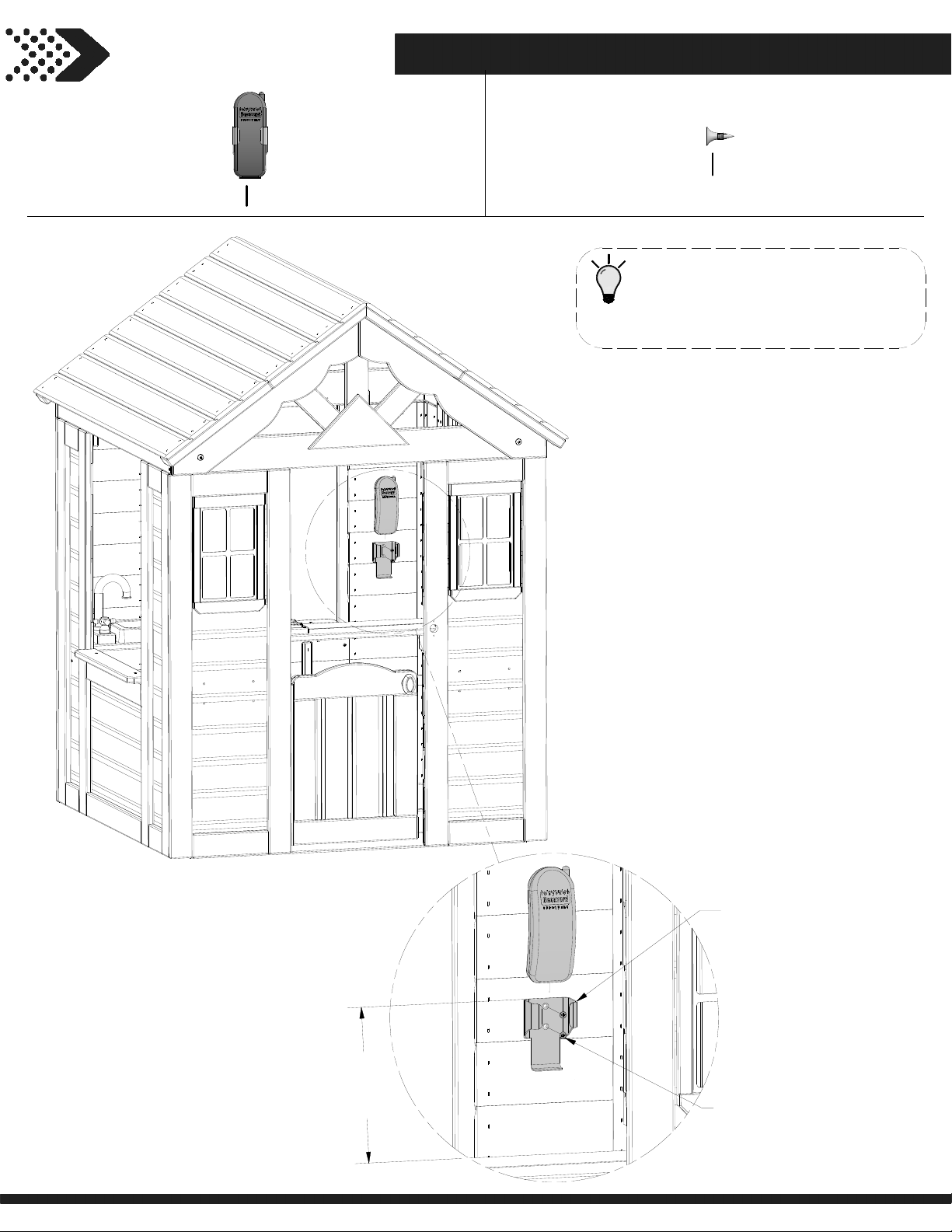
STEP 25
43
A100132
(x1)
PHONE KIT
H100124
(x2)
SCREW PFH
8 x 1/2
TIP:
CENTER PHONE AND MOUNT
USING THE DIMSENSION BELOW
OR YOUR DESIRED LOCATION.
132
(x1)
PHONE KIT
7
[
1
3
9
/
7
4
m
i
n
m
]
124
(x2)
SCREW PFH 8x1/2
Page 44
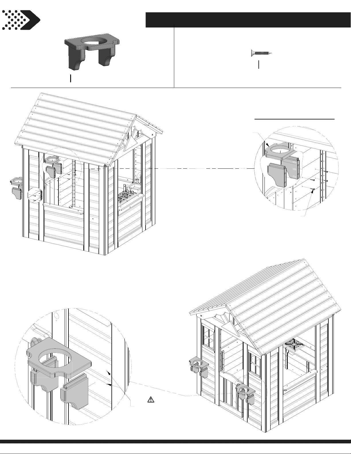
STEP 26
44
A6P00387
(x2)
FLOWER POT HOLDER - BLK
H100085
(x8)
387
(x1)
FLOWER POT HOLDER - BLK
SCREW PFH
8x1
REPEAT ON OPPOSITE SIDE
085
(x4)
SCREW - 1"
NOTE HOLE
LOCATIONS
Page 45
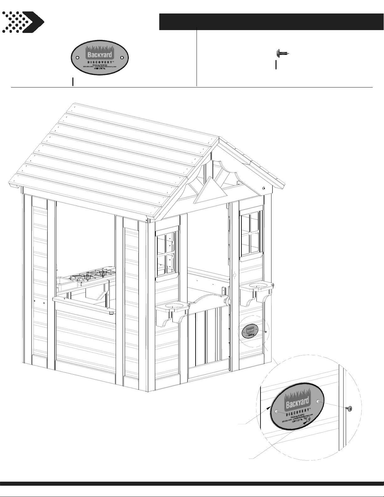
STEP 27
45
A4M00528
(x1)
BYD ID TAG (MEDIUM) AGES 2 TO 10
H100361
(x2)
SCREW PWH BLK
8x7/16
528
(x1)
BYD ID TAG (MEDIUM) AGES 2 TO 10
361
(x2)
SCREW - 7/16"
Page 46
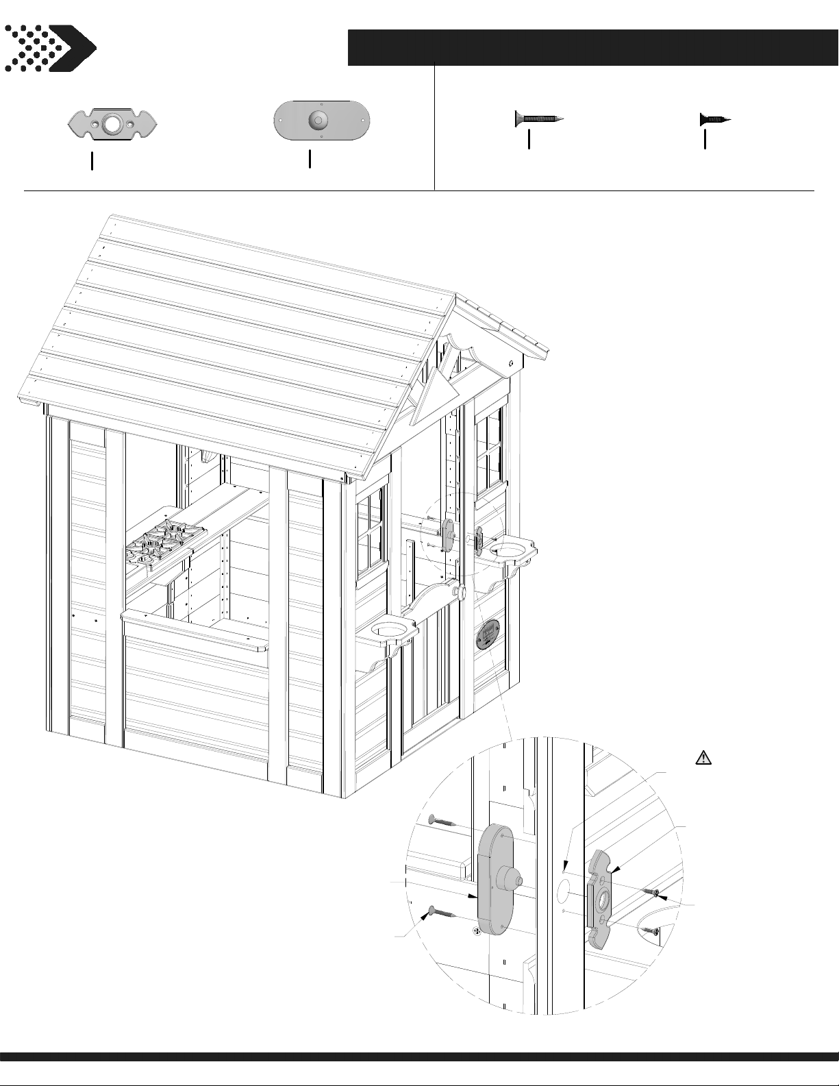
STEP 28
46
A6P00290
(x1)
DOOR BELL PLATE
A100174
(x1)
DOOR BELL
H100537
(x2)
SCREW PFH SD
8x1
H100624
(x2)
SCREW PFH BLK
6x5/8
174
(x1)
DOOR BELL
537
(x2)
SCREW - 1"
NOTE PILOT
HOLES.
290
(x1)
DOOR BELL PLATE
624
(x2)
SCREW - 5/8"
Page 47
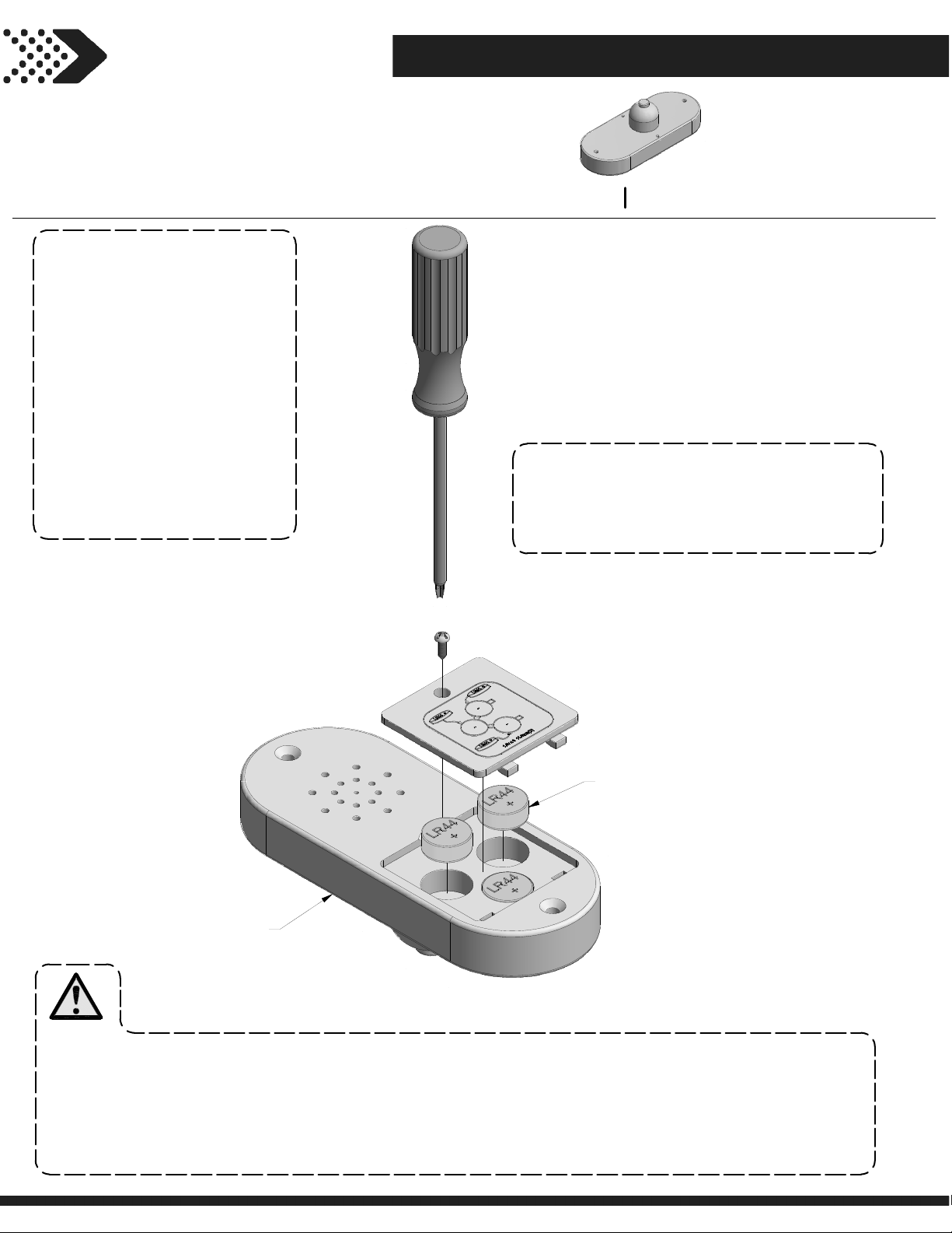
STEP 29
47
NOTE:
-DO NOT MIX OLD AND NEW
BATTERIES.
-DO NOT MIX ALKALINE,
STANDARD (CARBON-ZINC), OR
RECHARGEABLE (NI-CAD, NI-MH,
ETC.) BATTERIES.
-NON-RECHARGEABLE BATTERIES
ARE NOT TO BE RECHARGED.
-ONLY BATTERIES OF THE SAME
OR EQUIVALENT TYPE AS
RECOMMENDED ARE TO BE USED.
-BATTERIES ARE TO BE INSERTED
WITH THE CORRECT POLARITY.
-EXHAUSTED BATTERIES ARE TO
BE REMOVED FROM THE TOY OR
IF THE TOY IS TO BE LEFT
UNUSED FOR A LONG TIME.
-THE SUPPLY TERMINALS ARE
NOT TO BE SHORT-CIRCUITED.
A100174
NOTE:
USING A SCREW DRIVER, REPLACE BATTERIES BY
REMOVING SCREW IN BATTERY COVER, REMOVING
BATTERY COVER AND FOLLOWING DIRECTIONS FOR
BATTERY REPLACEMENT LOCATED ON THE BATTERY
COVER.
(x1)
DOOR BELL
LR44
(x3)
BATTERY (INCLUDED)
174
(x1)
DOOR BELL
WARNING:
1. KEEP BATTERIES OUT OF THE REACH OF CHILDREN.
2. SWALLOWING MAY LEAD TO SERIOUS INJURY OR DEATH IN AS LITTLE AS 2 HOURS, DUE TO CHEMICAL BURNS AND POTENTIAL
PERFORATION OF THE ESOPHAGUS.
3. IF YOU SUSPECT YOUR CHILD HAS SWALLOWED A BUTTON BATTERY, IMMEDIATELY SEEK URGENT MEDICAL ASSISTANCE.
4. EXAMINE DEVICES AND MAKE SURE THE BATTERY COMPARTMENT IS CORRECTLY SECURED, E.G. THAT THE SCREW OR OTHER
MECHANICAL FASTENER IS TIGHTENED. DO NOT USE IF COMPARTMENT IS NOT SECURE.
5. DISPOSE OF USED BUTTON BATTERIES IMMEDIATELY AND SAFELY. FLAT BATTERIES CAN STILL BE DANGEROUS.
6. TELL OTHER OF THE RISK ASSOCIATED WITH BUTTON BATTERIES AND HOW TO KEEP THEIR CHILDREN SAFE.
 Loading...