

Page 1
#16609-SL
01/24/2007
Customer Service
Marco Series
(Servicio al cliente)
1-800-437-0784
1000 Ternes Drive
Monroe, MI 48162
Techo a dos aguas 10’
10’ Wide Gable
Includes 10’x7’8-5/8” (305x235 cm), 10’x11’8-5/8” (305x357
cm), 10’x15’8-5/8” (305x479 cm) Building Instructions
Tools required
(Herramientas
necesarias)
❑ Hammer
(Martillo)
❑ Phillips
Screwdriver
(Desarmador cruz)
❑ Level
(Nivel)
❑ Ladder
(Escalera)
❑ Pencil
(Lápiz)
❑ Tape Measure
(Cinta métrica)
❑ Utility Knife
(Navaja)
❑ Paint Tools
(Herramientas
para pintar)
❑ Caulk Gun
(Pistola para
masillado)
❑ Wood Glue
(Pegamento para
madera)
- BEFORE YOU BEGIN -
First...
●
Check with your local building authority before erecting.
●
Read instructions thoroughly before you begin.
Building Codes
●
Our buildings are designed to meet most local and national
U.S. codes and are not meant to be used for living space.
●
General construction drawings can be provided.
Check All Parts
●
If a part is missing, circle the part in question and call.
●
Please note the primer color may vary on siding and
trim parts. This is a factory applied primer intended for
preparing your building for painting. This is NOT a finish
coat. This primer color variation will not affect the look of
your building once painted.
Important
●
Lumber is graded from one side, use most attractive
face to the outside.
●
In a drawing, a dotted line represents a part hidden from
view (like a part under a panel).
Assistance required
●
Assistance is necessary to handle, fit, and secure
some components.
Squareness is very Important!
●
Keep 90° corners and 90° perpendiculars throughout
the assembly to ensure all components fit together.
Check foundation size
●
Before starting on your foundation, make sure you are
building the correct size foundation for your building.
Safety!
●
Check for protruding nails, pound any protruding
nails into the wood or cut them off flush
Always wear OSHA-APPROVED safety
glasses throughout assembly process
Optional T ools
(Herramientas
opcionales)
❑ Electric Drill w/
#2 Phillips Tip
(Taladro eléctrico
Broca “Phillips”)
❑ Chalk Line
(Línea de marcar)
❑ Square
(Escuadra)
❑ Nail Pouch
(Bolsillo para
clavos)
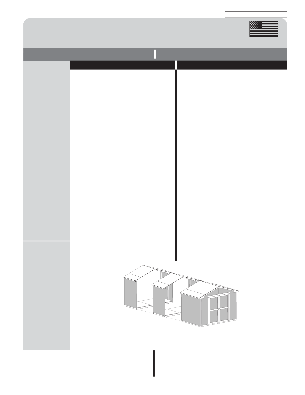
Base + 2
Extenders/
Extensiones
10’x15’ 8-5/8”
(305x479 cm)
Extensiones
10’x11’ 8-5/8”
(305x357 cm)
Made in the USA
Hecho en Estados Unidos
Instrucciones para edificios de 10’x7’8-5/8” (305x235 cm),
10’x11’8-5/8” (305x357 cm), 10’x15’8-5/8” (305x479 cm)
- ANTES DE EMPEZAR -
Primero...
●
Consulte la autoridad de construcción local antes de
construir el edificio.
●
Lea las instrucciones completamente antes de empezar.
Códigos de Construcción
●
Hemos diseñado nuestros edificios a que conformen con
todos los códigos de construcción locales y nacionales. Los
edificios no están proyectados como residencia.
●
Se disponen planes generales de construcción.
Compruebe todas las piezas
●
Si falta una pieza, indícala con un círculo y llámenos.
●
Aviso: El color del imprimador puede variar en la covertura
y las partes de la moldura. Este imprimador se aplica en la
fábrica y es para preparar su edificio para pintar. NO es una
capa de pintura terminada. La variación en el color del
imprimador no afectará la apariencia de su edificio al pintarlo.
Importante
●
La Madera está elaborada en un solo lado. Use el lado más
atractivo en el exterior.
●
Si falta una pieza, póngale un círculo y llámenos.
●
En un dibujo una línea punteada representa una pieza no
vista (por ejemplo, una pieza debajo de un panel)
Ayuda requerido
●
Seleccione un sitio nivelado.
●
Será necesario pedir ayuda para manejar, unir, y reforzar
algunas piezas.
¡Es preciso escuadrar el edificio!
●
Mantenga ángulos de 90° en las esquinas y los
perpendiculars durante la construcción para asegurar que
todas las piezas se unen correctamente.
Comprueba las dimensiones de la
cimentación.
●
Compruebe que las dimensiones de la cimentación son las
correctas para el edificio.
¡Seguridad!
●
Inspeccione para clavos sobresalientes; hinque cualquier
clavo sobresaliente en la madera o córtelo nivelados con la
madera
Siempre lleve gafas de seguridad
aprobadas por OSHA durante la
construcción.
Base + 1
Extenders/
Base
Building/Edificios
10’x7’8-5/8”
(305x235 cm)
We manufacture kits from select construction grade lumber and engineered wood products. Construction grade
lumber, a product cut from trees, has many natural characteristics and blemishes that may be present in some of
the pieces you receive in your kit. Natural characteristics and blemishes in construction lumber may include knots,
torn wood grain along edges, minor cracks/splits, twists, limited bark along edges and pitch pockets that may
exude sap. Be assured that the individual parts have been cut and inspected to remove as many of the wood’s
natural, less appealing characteristics as possible. These characteristics and/or blemishes will not affect the
strength, durability, or structural integrity of the finished product. Generally, the exterior trim parts selected for
your kit are graded from only one side and should be installed with the most attractive side outward. Our limited
warranty does not cover the natural characteristics and blemishes that occur with construction grade lumber
products.
Fabricamos nuestros equipos de madera elaborada y de productos maquinados de madera. La madera
elaborada, producto de árboles, tiene muchas características e imperfecciones naturales que puedan
tener algunas piezas contenidas en el equipo. Estas imperfecciones y características pueden incluir
nudos, grano rasgado sobre el borde, rajas/grietas pequeñas, torsiones, cortezas en el borde, y bolsos
que exuden savia. Asegurams que hemos cortado e inspeccionado las partes individuales para eliminar
las características naturales menos atractivas posibles. Estas características y/o imperfecciones no
afectarán la fuerza, durabilidad ni la integridad estructural del producto final. Po lo general, las piezas de
moldura exterior seleccionadas para su equipo se elaboran de un solo lado y deben ser instaladas con
la parte más atractiva por fuera. Nuestra garantía limitada no cubre las características e impefecciones
que ocurren con los productos de madera elaborada.
Page 2
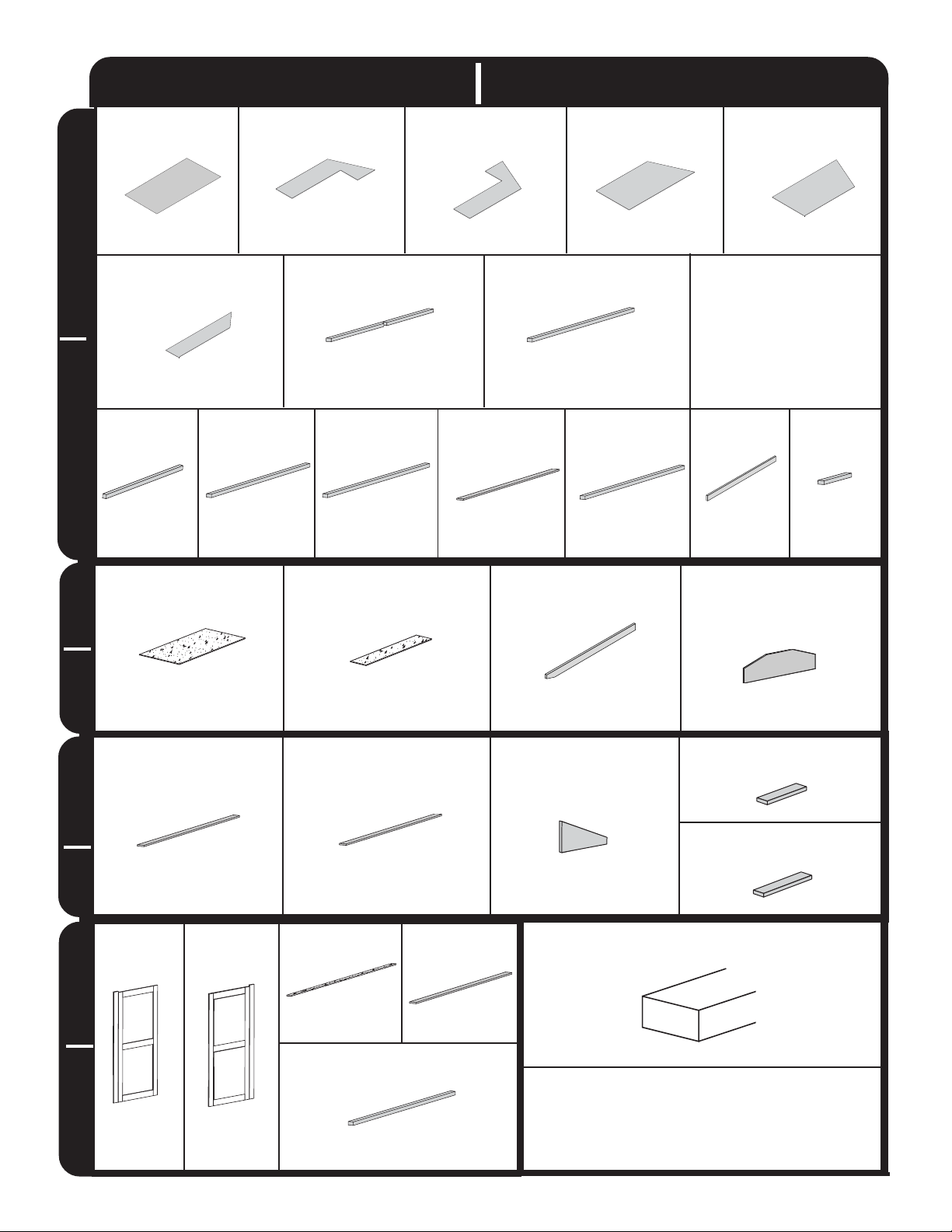
10’ X 7’ 8-5/8” (305x235 cm)
PARTS LIST
48”x72”
(122x183 cm)
48”x95-13/16”
(122x243 cm)
48”x95-13/16”
(122x243 cm)
10’ X 7’ 8-5/8” (305x235 cm)
LISTA DE PIEZAS
48”x95-13/16”
(122x243 cm)
48”x95-13/16”
(122x243 cm)
F
MURO
L
2x3x45-3/4”
(116 cm)
WALLS
NB
TECHO
x4
11-7/8”x79-7/16”
(30x202 cm)
2x3x92-5/8”
(235 cm)
x2
PM
48”x96”
(122x244 cm)
G
2L/2R
PA
x2
PB
x1
2x3x93”
(236 cm)
2x3x77”
(196 cm)
20”x96”
(51x244 cm)
H
x8
x2
OY
PL
2x3x72”
(183 cm)
Rafter
x1
J
2x3x93”
(236 cm)
2x3x70-1/4”
(178 cm)
x4
OZ
2x4x66-1/2” (169 cm)
Viga
x1
x6
x1
K
2x3x50-5/8”
(144 cm)
OD
Gusset
x4
LN
Placa de Unión
6” x 20”
(15 x 51 cm)
2x3x16-1/2
(56 cm)
x1
x1
ROOF
P
1”x3”x94-3/4”
(2.5x7.6x241 cm)
MOLDURA
TRIM
HP
Left
Door
Puerta izquierda
PUERTA
DOOR
V
x1
Right
Door
Puerta derecha
W
x1
x2
x2
Q
HS
3/8”x1-3/4”x69”
(.9x4.5x175 cm)
D
E
1x3x94-3/4”
(241 cm)
1”x3”x72”
(2.5x7.6x183 cm)
x1
2”x3”x68-1/4”
(2x7.6x173 cm)
x2
x2
TC
3/4”x7-3/4”x16”
(1.9x20x41 cm)
T
Note
Double and Triple
Letter Part
identification letters
are stamped
on part and read
horizontally, single
letter part letters
x1HJ
not stamped on
parts.
Lumber Sizes
(Dimensión nominal)
x2
Nominal Size
2 x 4
2 x 3
1 x 4
1 x 3
x6
N
3/4”x3-1/2”x6”
(1.9x9x15 cm)
OR
U x4
3/4”x3-1/2”x8”
(1.9x9x21 cm)
x4
Z
RS
RS
=
=
=
=
RS
Dimensiones de la madera
(Dimensiones verdaderas)
1-1/2” x 3-1/2” (3.8 x 8.9 cm)
1-1/2” x 2-1/2” (3.8 x 6.3 cm)
3/4” x 3-1/2” (1.9 x 8.9 cm)
3/4” x 2-1/2” (1.9 x 6.3 cm)
OR
Aviso
Dos letras o tres
letras de
identificación están
marcadas
horizontalmente en
las piezas. Letras de
identificación de una
sola letra no están
en las piezas.
Actual Size
x6
3/4”x2-1/2”x6”
(1.9x6x15 cm)
3/4”x2-1/2”x8”
(1.9x6x21 cm)
x4
2
Page 3
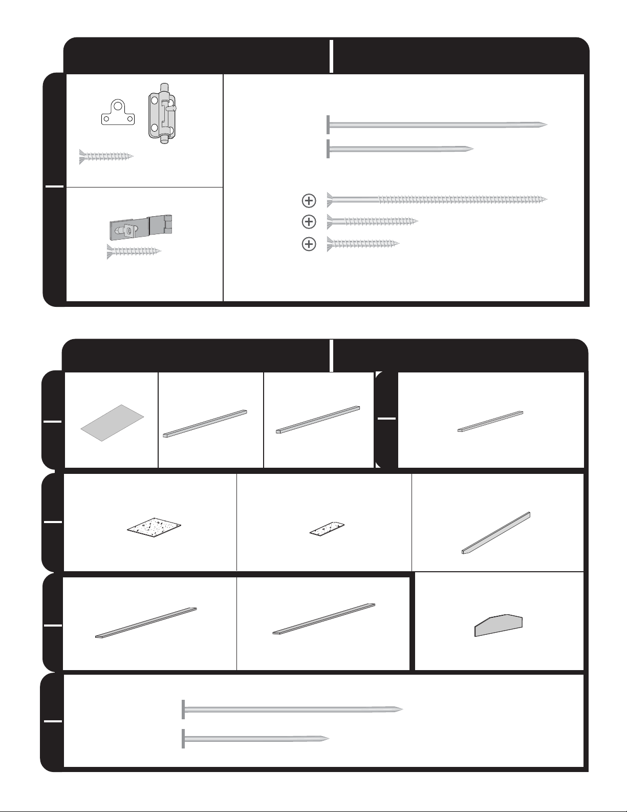
10’ X 7’ 8-5/8” (305x235 cm)
PARTS LIST
10’ X 7’ 8-5/8” (305x235 cm)
LISTA DE PIEZAS
ÍA
3/4” (1.9 cm) x6
FERRETER
3/4” (1.9 cm) x7
HARDWARE
10’ X 4’ (305 x 122 cm)
EXTENDER PARTS LIST
3/8”x48”x72”
(.9x122x183 cm)
MURO
x1
2x3x70-1/4”
x1
(178 cm)
3” (7.6 cm)
2” (5.0 cm)
3” (7.6 cm)
1-1/4” (3.2 cm)
1” (2.5 cm)
Actual Size
LISTA DE PIEZAS DE EXTENSIÓN
2x3x48”
(122 cm)
Dimensiones V erdadera
10’ X 4’ (305 x 122 cm)
2x4x69”
(175 cm)
Treated Wood/
PISO
madera conservada
x 232
x 450
x 16
x 90
x 27
W ALL
A
(122x122 cm)
OZ
x2
47-7/8”x48”
TECHO
O
ROOF
1x3x48” (122 cm)
MOLDURA
TRIM
FO x2
ÍA
FERRETER
HARDW ARE
Actual Size
x2
x4
Y
FP
3” (7.6 cm)
2” (5.0 cm)
NK
20”x48”
(51x122 cm)
1”x3”x48” (2.5x7.6x122 cm)
x2
x 194
E x6
FLOOR
x2
x2
Rafter
TC
Gusset
N
2x4x66-1/2” (169 cm)
6” x 20” (15 x 51 cm)
Dimensiones V erdadera
x 24
Viga
x4
Placa de Union
x4
3
Page 4
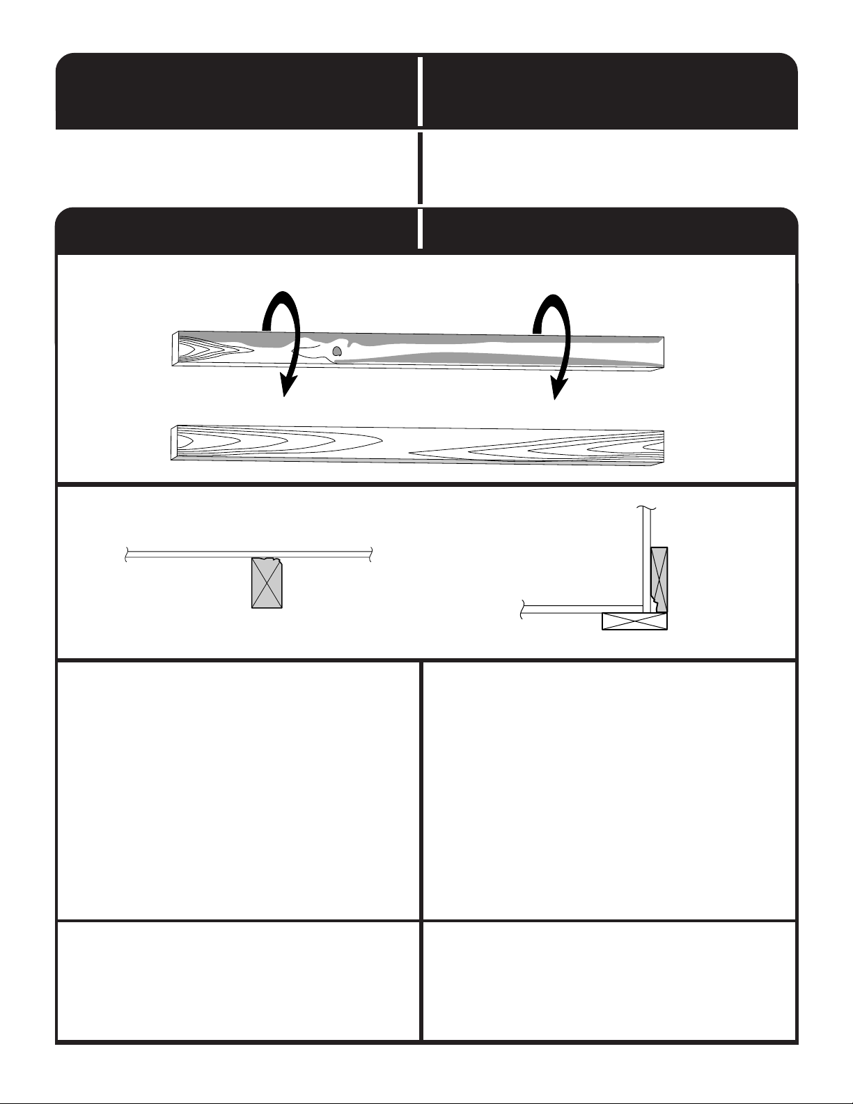
IMPORTANT!!!
Building Tip
IMPORTANTE!!!
Consejo
FOR THE BEST LOOKING FINISHED PRODUCT WE
RECOMMEND THAT YOU INSPECT, SORT AND LAY
OUT MATERIALS PRIOR TO BEGINNING
ASSEMBLY OF YOUR BUILDING
HELPFUL MATERIAL NOTICE
B C
CON EL FIN DE OBTENER EL PRODUCTO
ACAB ADO DE MEJOR ASPECT O
RECOMENDAMOS QUE INSPECCIONE,
CLASIFIQUE Y ORGANICE LOS MATERIALES
ANTES DE EMPEZAR A MONTAR SU EDIFICIO
AVISO ÚTIL SOBRE LOS MATERIALES
A
Wood is a natural product that has inherent blemishes. All
interior framing is graded for structural strength and not
appearance. Exterior trim is graded for one good side per
industry standards.
• Blemishes can be easily installed to provide the best
appearance. (Fig. A)
• Install wall framing with any blemished sides toward the
siding and facing rear of building. (Fig. B)
• Install corner trim, gable trim and fascia with any blemished
sides toward the siding material. (Fig. C)
Always install the material leaving the best edge and best
surface visible.
Please remember that these blemishes in no way negatively
affect the strength or integrity of our product.
Please feel free to call our Consumer Help Line - Toll Free
1-800-437-0784
Monday through Friday
8:00 AM to 5:00 PM EST
Saturday (March through October)
10:00 AM to 4:00 PM EST
La madera es un producto natural que tiene defectos
inherentes. Todo la estructura interior ha sido aprobada por
ofrecer una resistencia estructural y no por su aspecto. La
guarnición exterior ha sido aprobada por tener un buen lado
según las normas de la industria.
• La parte con defectos puede instalarse fácilmente de modo
que el edificio tenga el mejor aspecto. (Fig. A)
• Instale el entramado de la pared con los lados con defectos
apuntando hacia los costados y haciendo frente a la parte
trasera del edificio. (Fig. B)
• Instale la guarnición de las esquinas, la guarnición de
los hastiales y las impostas con los lados con
defectos apuntando hacia el material lateral. (Fig. C)
Instale siempre el material dejando visibles el mejor borde y la
mejor superficie.
Recuerde que estos defectos no afectan de forma negativa la
resistencia o la integridad de nuestros productos.
Llame de forma gratuita a nuestra línea de ayuda al
consumidor
1-800-437-0784
Lunes a viernes
8:00 AM a 5:00 PM, hora estándar del este
Sábado (marzo a octubre)
10:00 AM a 4:00 PM, hora estándar del este
4
Page 5
;;
;;
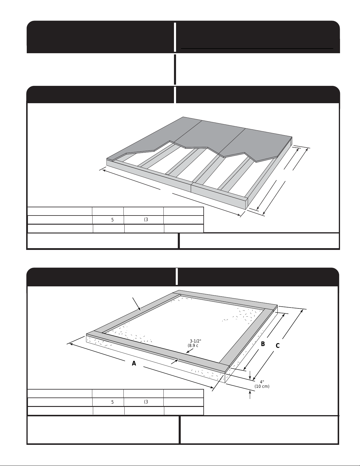
FOUNDATION OPTIONS
YOU MUST ASSEMBLE YOUR BUILDING ON A
WOOD FLOOR OR CONCRETE SLAB.
OPCIONES PARA LA CIMENTACIÓN
HAY QUE CONSTRUIR EL EDIFICIO SOBRE UN BASE
DE MADERA O DE CONCRETO.
SITE PREPARATION
• Site must be properly leveled.
• Site should have natural drainage
and no standing water
A) Building the optional wood floor
frame.
TO CONSTRUCT THE WOODEN FLOOR FRAME
, BEGIN ON THE PAGE 4.
Building Size
Dimensiones del edificio
10’x 7’8-5/8” (305 x 235cm)
10’x 11’8-5/8” (305 x 357cm)
10’x 15’8-5/8” (305 x 479cm)
Important: Square floor and level to ground
before beginning assembly of building.
AB
A
A
120” (305 cm)
A
120” (305 cm)
120” (305 cm)
89-5/8” (228 cm)
A
A
137-5/8” (350 cm)
185-5/8” (471 cm)
PREPARACIÓN DEL SITIO
• El sitio debe de estar nivelado correctamente.
• Instale una barrera contra yerbajos debajo de la
estructura.
A) El edificio del marco de suelo de madera
opcional.
PARA CONSTRUIR EL MARCO DE PISO DE
MADERA , COMIENCE EN LA PÁGINA 4.
BC
A
C
92-5/8” (235 cm)
140-5/8” (357 cm)
188-5/8” (479 cm)
Importante: Asegure que el suelo está nivelado y
escuadrado antes de construir el edificio.
B) Concrete Slab Foundation
Soleras Inferiors Tratadas
Building Size
Dimensiones del edificio
10’x 7’8-5/8” (305 x 235cm)
10’x 11’8-5/8” (305 x 357cm)
10’x 15’8-5/8” (305 x 479cm)
Fasten treated 2x4 sill plates to slab using approved
concrete anchors. (Fasteners not inc luded.)
Cut treated 2x4 sill plates to length Corte los tableros tratados 2x4 a longitud
Treated Sill
A
AB
A
A
120” (305 cm)
A
120” (305 cm)
120” (305 cm)
85-5/8” (217 cm)
A
A
133-5/8” (339 cm)
181-5/8” (461 cm)
B) Base en losa de concreto
3-1/2"
(8.9 cm)
C
92-5/8” (235 cm)
140-5/8” (357 cm)
188-5/8” (479 cm)
Fije las soleras inferiores tratadas, de tamaño 2x4, a la losa
usando anclajes de concreto aprobados. (Los anclajes no
están incluidos.)
B
4"
(10 cm)
C
5
Page 6
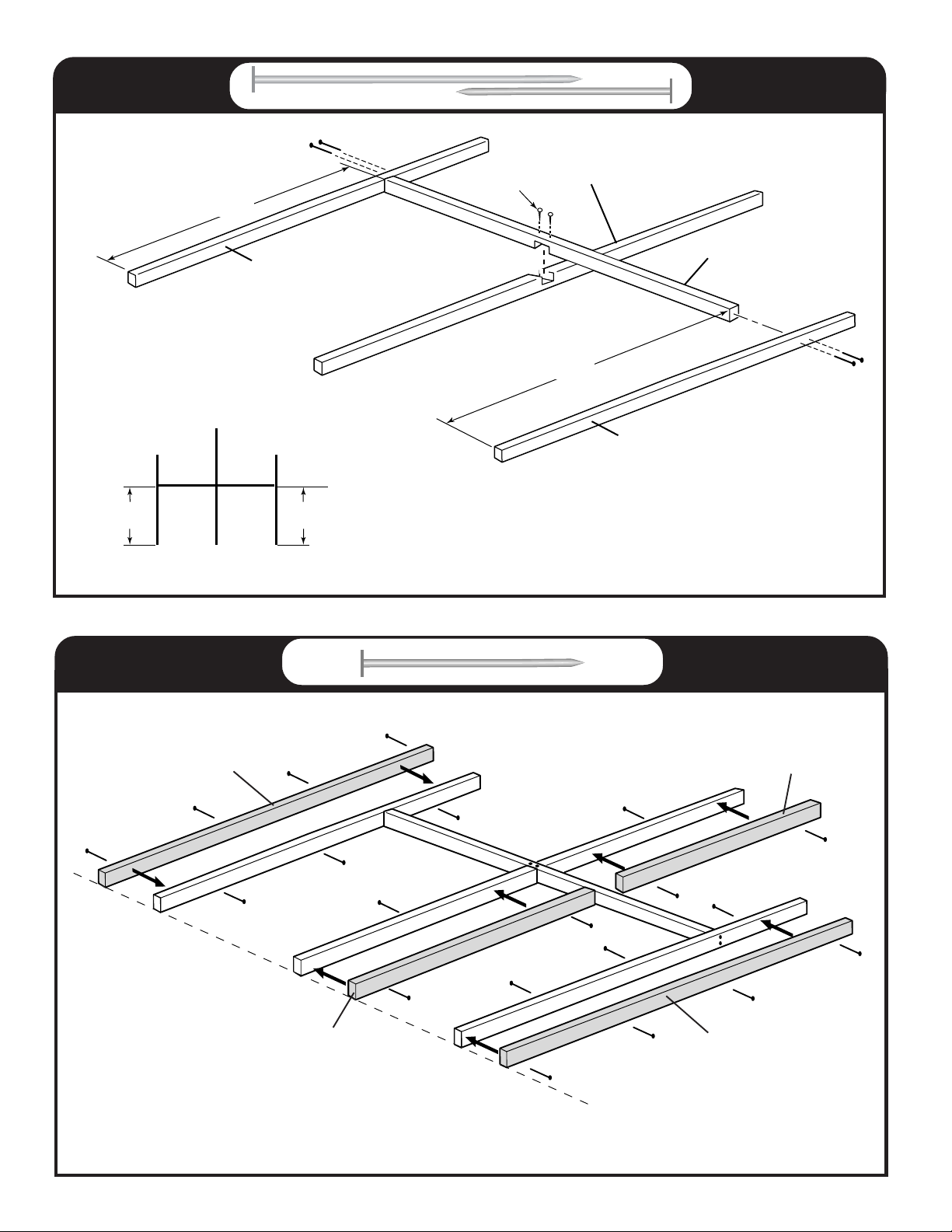
BA CK W ALL
3” (7.6 cm) x 4
2” (5 cm) x 2
MURO
POSTERIOR
45-3/4"
(116 cm)
45-3/4"
(116 cm)
PB
PA
PA
PB PB
45-3/4"
(116 cm)
bottom/
fondo
2 - 2" (5 cm)
Nails/Clavo
PA
PA
45-3/4"
(116 cm)
PB
BA CK W ALL
2”(5 cm)
x20
MURO
POSTERIOR
PB NB
NB
PB
Flush/
Nivelado
6
Page 7
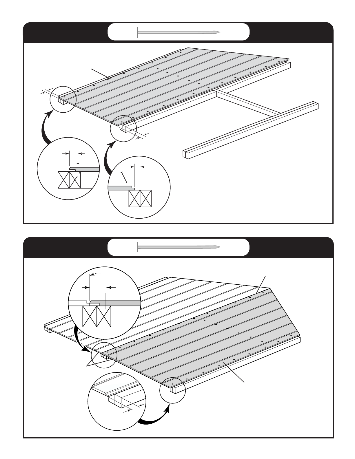
BACK WALL
1"
(2.5 cm)
1-1/8”
(2.8 cm)
2”(5 cm)
x26
MURO
POSTERIOR
J
1"
(2.5 cm)
3/4”
(2 cm)
BACK WALL
Flush/
Nivelado
Flush/
Nivelado
1-1/2”
(3.8 cm)
2”(5 cm)
x 26
MURO POSTERIOR
Caulk seam/
Masillado la costura
K
1"
(2.5 cm)
7
Page 8
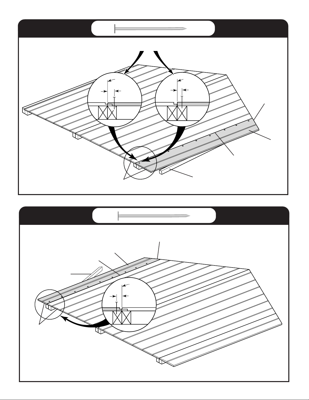
BA CK W ALL
2”(5 cm)
x90
MURO POSTERIOR
Note: Wing wall Panels (L)
are short at top for tolerance
3-A
Flush/
Nivelado
1-1/8”
(2.9 cm)
Flush/
Nivelado
Either / Or
Nota: los paneles de pared (L) son cortos
en la parte superior para la tolerancia
Flush/
Nivelado
3/4”
(1.9 cm)
See Note/
vaya a nota
L
Caulk seam/
Masillado la costura
Temporary Support/
apoyo no permanente
OY
FRONT W ALL
Note: Wing wall Panels (L)
are short at top for tolerance
Caulk seam/
Masillado la costura
OY
Temporary Support/
apoyo no permanente
Flush/
Nivelado
L
3-A
Flush/
Nivelado
3/4”
(2 cm)
2”(5 cm)
x 9
See Note/
vaya a nota
MURO DELANTERO
Nota: los paneles de pared (L) son cortos
en la parte superior para la tolerancia
8
Page 9
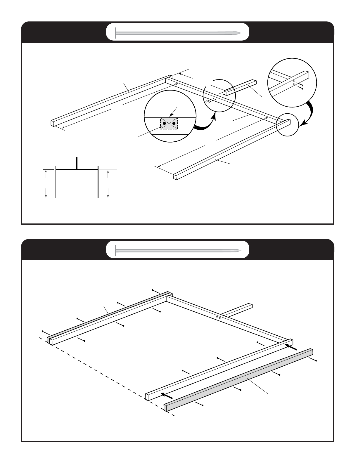
FRONT WALL
3”(7.6 cm)
x 6
MURO DELANTERO
LN
PL
70-1/4"
(178 cm)
PB PB
FRONT WALL
70-1/4"
(178 cm)
70-1/4"
(178 cm)
PB
LN
bottom/
fondo
Flush/
Nivelado
3”(7.6 cm)
x 14
46-1/2"
(118 cm)
LN
PL
70-1/4"
(178 cm)
PB
MURO DELANTERO
PB
PB
Flush/
Nivelado
9
Page 10
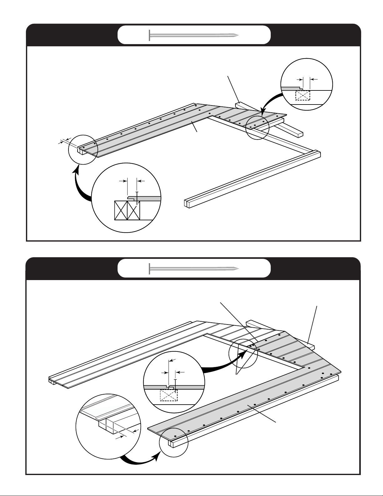
FRONT W ALL
1"
(2.5 cm)
1-1/8”
(2.8 cm)
2”(5 cm)
x 20
G
Temporary Support/
apoyo no permanente
MURO
DELANTERO
1-1/4”
(3.2 cm)
FRONT W ALL
1"
(2.5 cm)
2”(5 cm)
x 20
Caulk seam/
Masillado la costura
Flush/
Nivelado
1”
(2.5 cm)
Flush/
Nivelado
MURO
DELANTERO
Temporary Support/
apoyo no permanente
H
10
Page 11
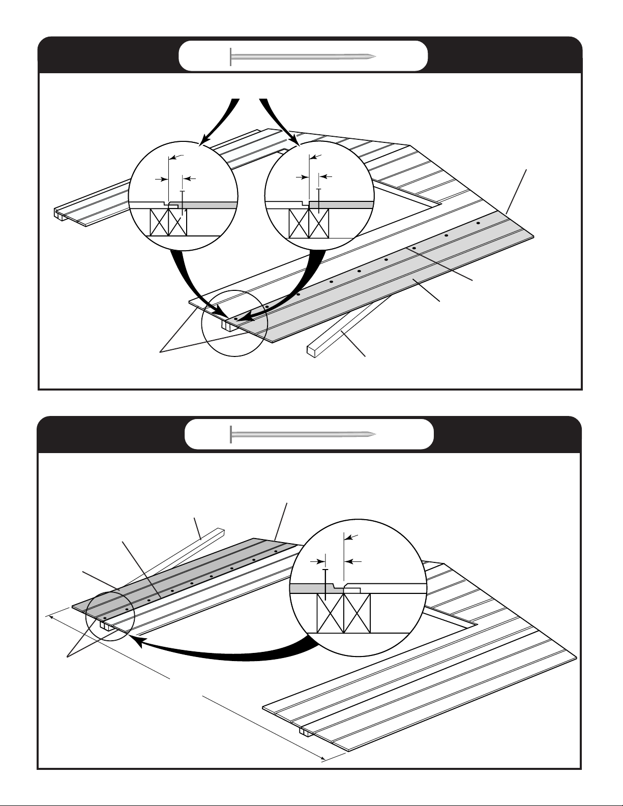
FRONT WALL
2”(5 cm)
x 9
MURO
DELANTERO
Note: Wing wall Panels (L)
are short at top for tolerance
Flush/
Nivelado
Flush/
Nivelado
Either / Or
1-1/8”
(2.9 cm)
Flush/
Nivelado
Nota: los paneles de pared (L) son cortos
en la parte superior para la tolerancia
3/4”
(1.9 cm)
Caulk seam/
Masillado la costura
L
OY
Temporary Support/
apoyo no permanente
See Note/
vaya a nota
FRONT WALL
Note: Wing wall Panels (L)
are short at top for tolerance
Temporary Support/
apoyo no permanente
Caulk seam/
Masillado la costura
L
Flush/
Nivelado
119-3/4"
(304 cm)
OY
2”(5 cm)
x 9
See Note/
vaya a nota
MURO DELANTERO
Nota: los paneles de pared (L) son cortos
en la parte superior para la tolerancia
Flush/
Nivelado
3/4”
(2 cm)
11
Page 12
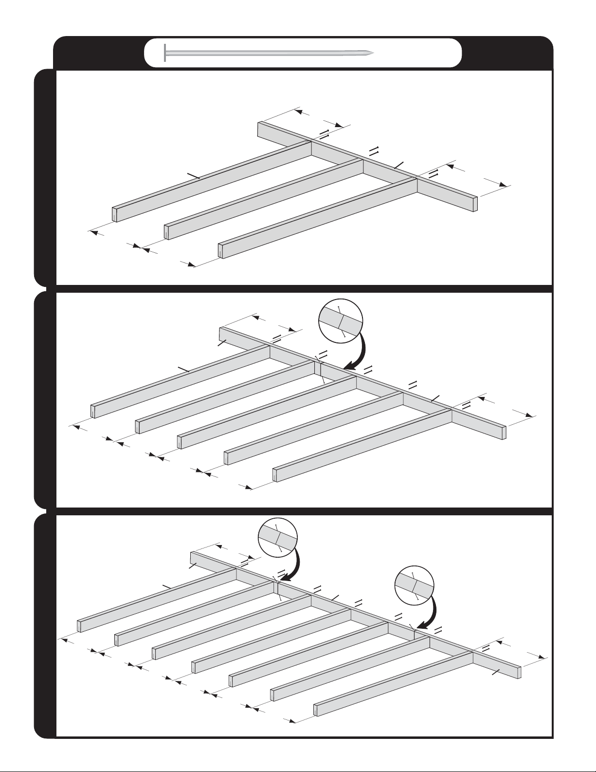
3”(7.6 cm)
SIDE WALL
x12 (10’x7’ 8-5/8”)
x 24 (10’x11’ 8-5/8”)
x 36 (10’x15’ 8-5/8”)
DELANTERO
x2 x2
22-5/16"
(57 cm)
Top
Parte Superior
MURO
24"
(61 cm)
10x7’ 8-5/8”
x2 x2
24"
(61 cm)
10x11’ 8-5/8”10x15’ 8-5/8” (305x235 cm)(305x357 cm)(305x479 cm)
24"
(61 cm)
OZ x3
24"
(61 cm)
OZ x5
(61 cm)
24"
NK
24"
(61 cm)
22-1/8"
(57 cm)
PM
22-5/16"
(57 cm)
Top
Parte Superior
PM
22-3/8"
(57 cm)
x2 x2
22-1/8"
(57 cm)
NK
24"
(61 cm)
24"
(61 cm)
OZ x7
24"
(61 cm)
24"
(61 cm)
24"
(61 cm)
24"
(61 cm)
12
PM
Top
Parte Superior
NK
22-3/8"
(57 cm)
Page 13
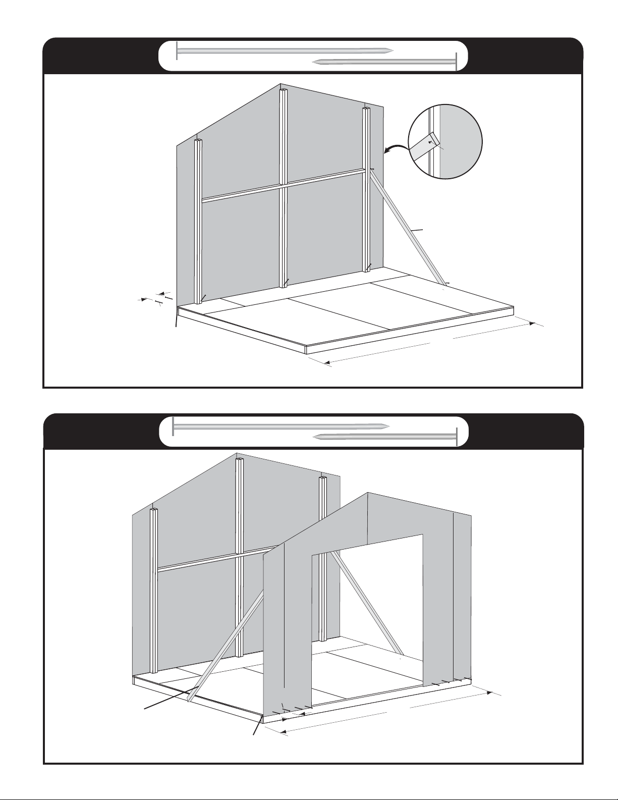
2"
(5 cm)
ERECTING
WALLS
Center Wall Assembly
on Floor
centre la asamblea de la
pared sobre el piso
12"
(30 cm)
2"
(5 cm)
Nivelado
Flush
3"
(7.6 cm)
2” (5 cm) x 11
3"
(7.6 cm)
3"
(7.6 cm)
3” (7.6 cm) x 7
Temporary Support
apoyo no permanente
120"
(305 cm)
CONSTRUYENDO
LOS MUROS
Level Wall and Brace, Do not
sink nails completely
Nivele la pared y refuérzala.
No hinque los clavos
OY
2"
(5 cm)
completamente.
ERECTING
WALLS
OY
Temporary Support
apoyo no permanente
2” (5 cm) x 8
Flush
Nivelado
2"
(5 cm)
(30 cm)
12"
13
3” (7.6 cm) x 6
120"
(305 cm)
Level Wall and Nail
Nivele la pared y
clave.
CONSTRUYENDO
LOS MUROS
Center Wall Assembly
on Floor
centre la asamblea de la
pared sobre el piso
Page 14
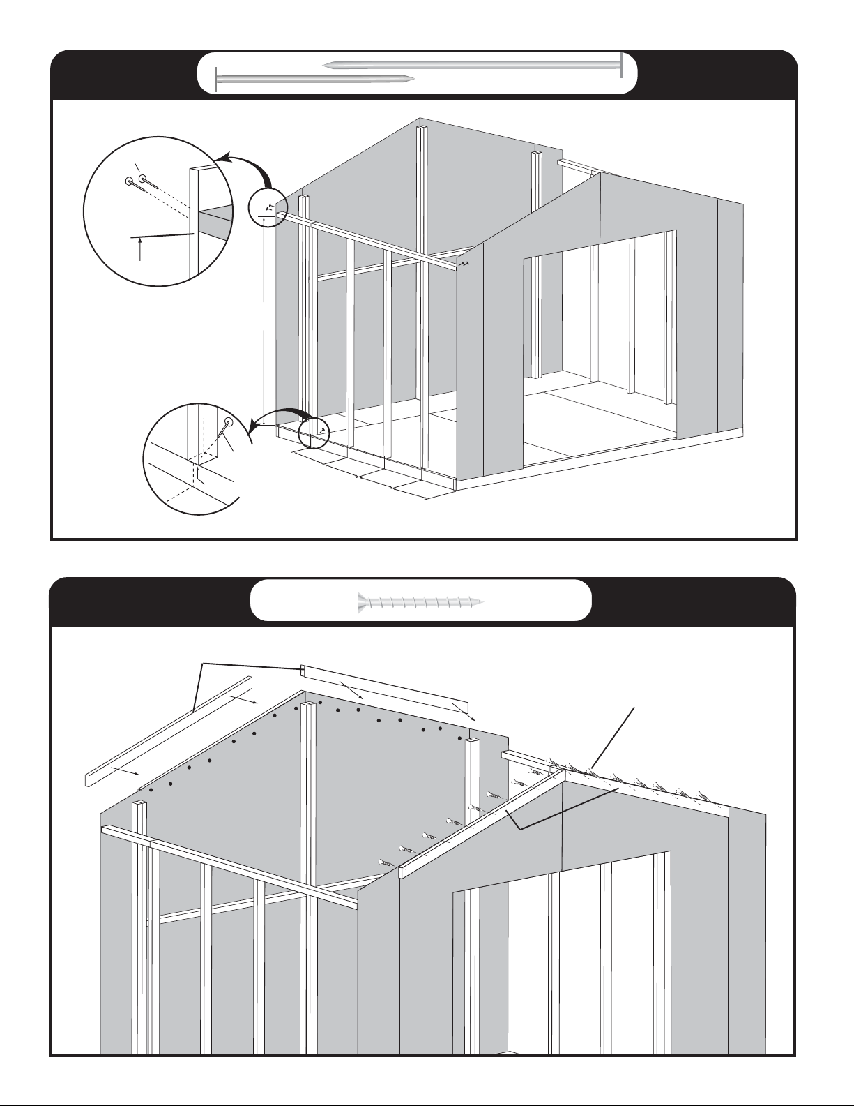
ERECTING
WALLS
(2) 2" Nails/Clavos
70-1/4"
3”(7.6 cm) x6
70-1/4"
(178.4 cm)
2”(5 cm) x8
CONSTRUYENDO
LOS MUROS
x 40
x 40
TRIM
3"(7.6 cm)
Nail/Clavo
Flush/Nivelado
OD
Stagger Screws
escalonar tornillo
24"
(61 cm)
24"
(61 cm)
24"
(61 cm)
22-3/8"
(56.5 cm)
1-1/4”(3.2 cm)
x32
OD
MOLDURA
x 40x 40
Flush to top of panel
parte superior nivelado del
panel
14
Page 15
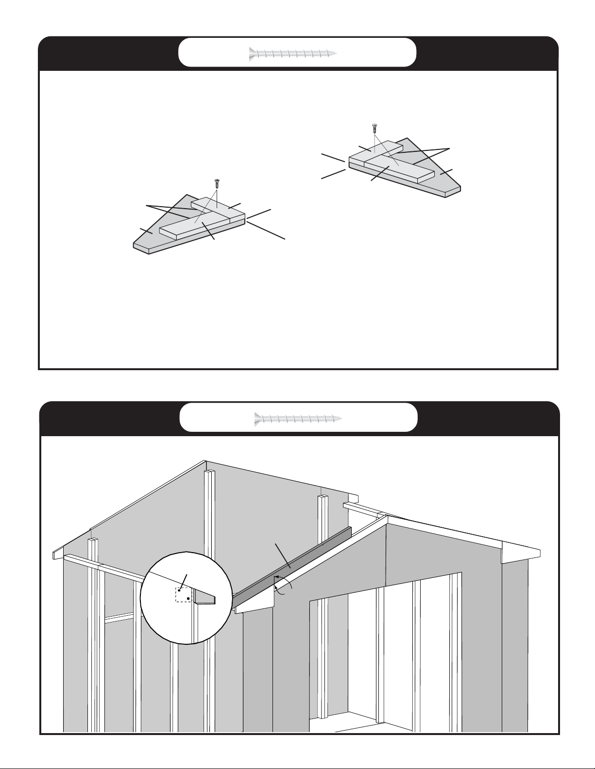
TRIM
1-1/4”(3.2 cm)
x8
Flush
Navelado
U
Center/
centro
MOLDURA
x 40x 40
Glue
Pegamento
TRIM
Glue
Pegamento
T
Center/
centro
Right
Derecha
x2
T
Flush
Navelado
U
Z
Flush
Navelado
Flush
Navelado
Z
Left
Izquierda
x2
1-1/4”(3.2 cm)
x8
MOLDURA
x 40x 40
x4
1-1/4"
(3.2 cm)
Straight Edge
borde recto
Flush
Nivelado
15
Page 16
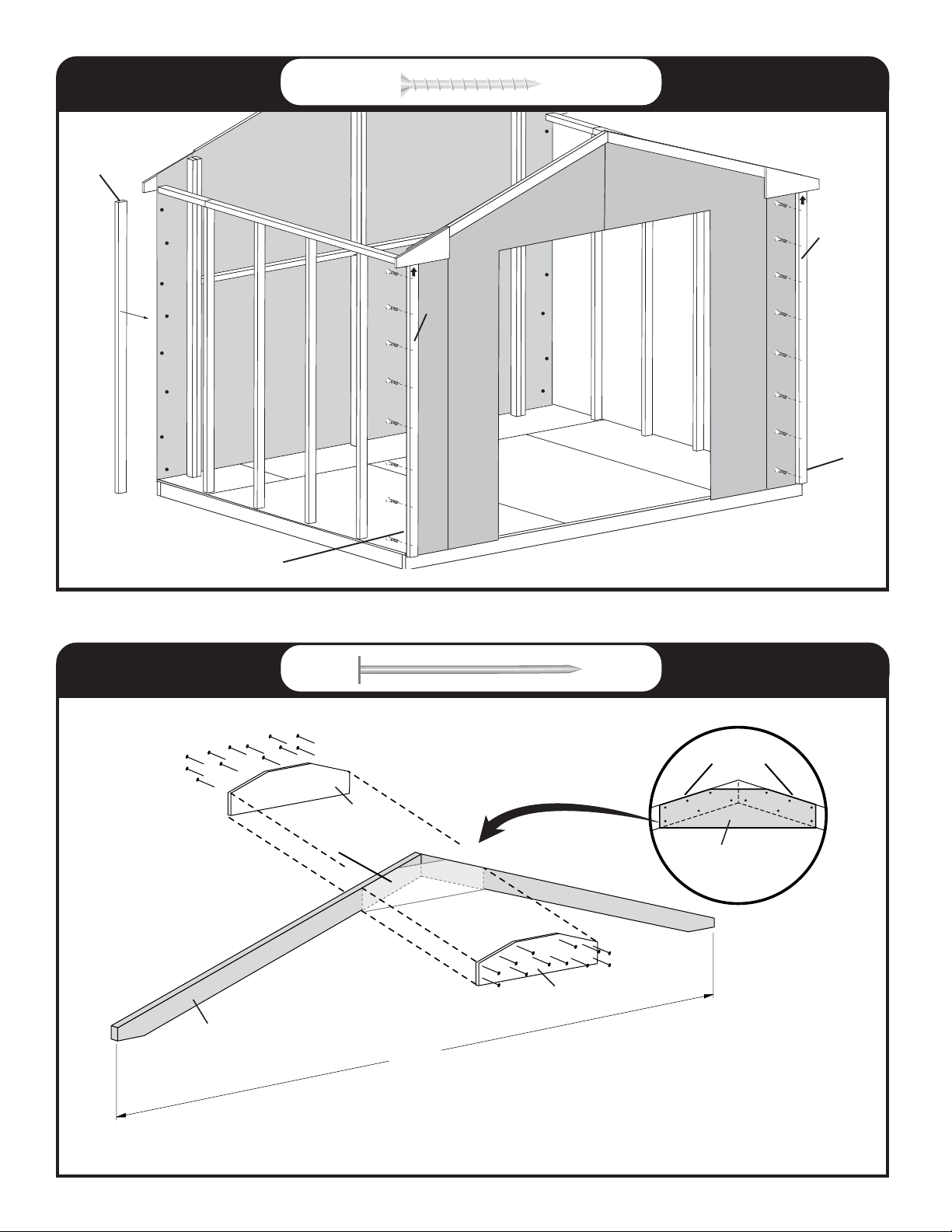
OY
TRIM
1-1/4”(3.2 cm)
x32
OY
MOLDURA
x 40
x 40
OY
Flush
Nivelado
Stagger Screws
escalonar tornillo
ROOF
Flush
Nivelado
Glue
Pegamento
x4
2”(5 cm)
x60
N
TECHO
x 40
x 40
Flush
Nivelado
N
x3
10x7’-8-5/8”
10x7’-8-5/8”
(305x235 cm)
N
TC x2
126"
(320 cm)
16
x5
10x11’-8-5/8”
10x11’-8-5/8”
(305x357 cm)
x7
10x15’-8-5/8”
10x15’-8-5/8”
(305x479 cm)
Page 17
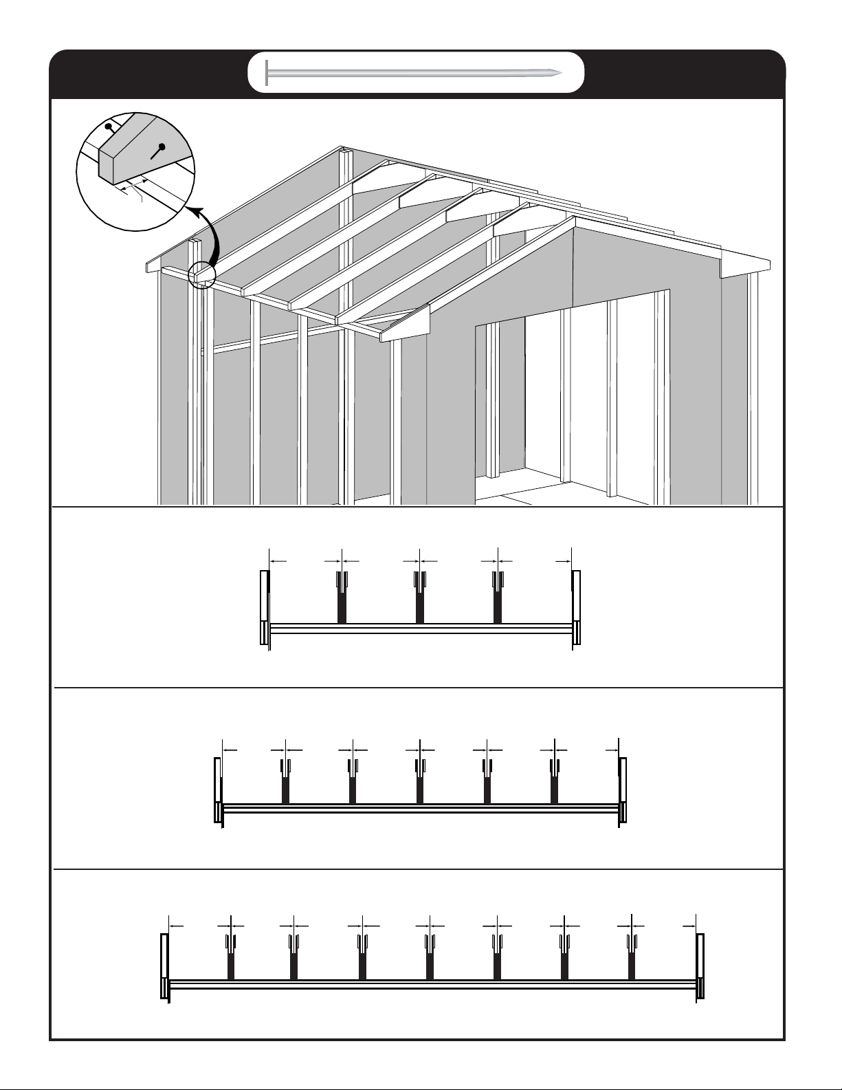
ROOF
3" (7.6 cm)
3”(7.6 cm)
x12
TECHO
x 40x 40
10x7’-8-5/8”
(305x235 cm)
10x11’-8-5/8”
(305x357 cm)
10x15’-8-5/8”
(305x479 cm)
22-1/8"
(56 cm)
22-1/8"
(56 cm)
24"
(61 cm)
22-1/8"
(56 cm)
(61 cm)
24"
24"
(61 cm)
24"
(61 cm)
24"
(61 cm)
24"
(61 cm)
24"
(61 cm)
24"
(61 cm)
24"
(61 cm)
22-3/8"
(56.7 cm)
24"
(61 cm)
24"
(61 cm)
22-3/8"
(56.8 cm)
24"
(61 cm)
Door side
Puerta lado
Door side
Puerta lado
22-3/8"
(56.8 cm)
Door side
Puerta lado
17
Page 18
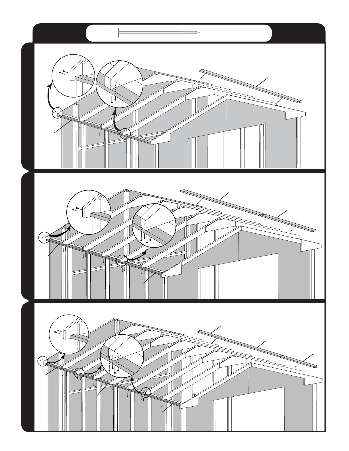
TRIM
HP
10x7’ 8-5/8”10x11’ 8-5/8”10x15’ 8-5/8” (305x235 cm)(305x357 cm)(305x479 cm)
2”(5 cm)
x20 (10’x7’ 8-5/8”)
x 24 (10’x11’ 8-5/8”)
x 36 (10’x15’ 8-5/8”)
HP
MOLDURA
HP
HP
FP
FP
FP
HP
FP
FP
HP
FP
18
Page 19
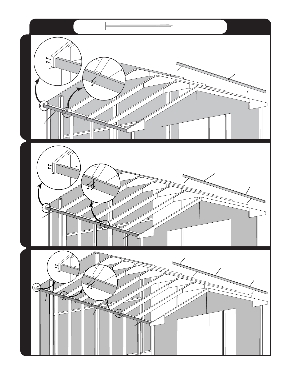
TRIM
2”(5 cm)
x20 (10’x7’ 8-5/8”)
x 32 (10’x11’ 8-5/8”)
x 44 (10’x15’ 8-5/8”)
MOLDURA
Flush
Nivaledo
HS
10x7’ 8-5/8”10x11’ 8-5/8”10x15’ 8-5/8” (305x235 cm)(305x357 cm)(305x479 cm)
Flush
Nivaledo
HS
HP
HS
FO
HP
HS
FO
Flush
Nivaledo
FO
FO
HS
FO
HS
FO
19
Page 20
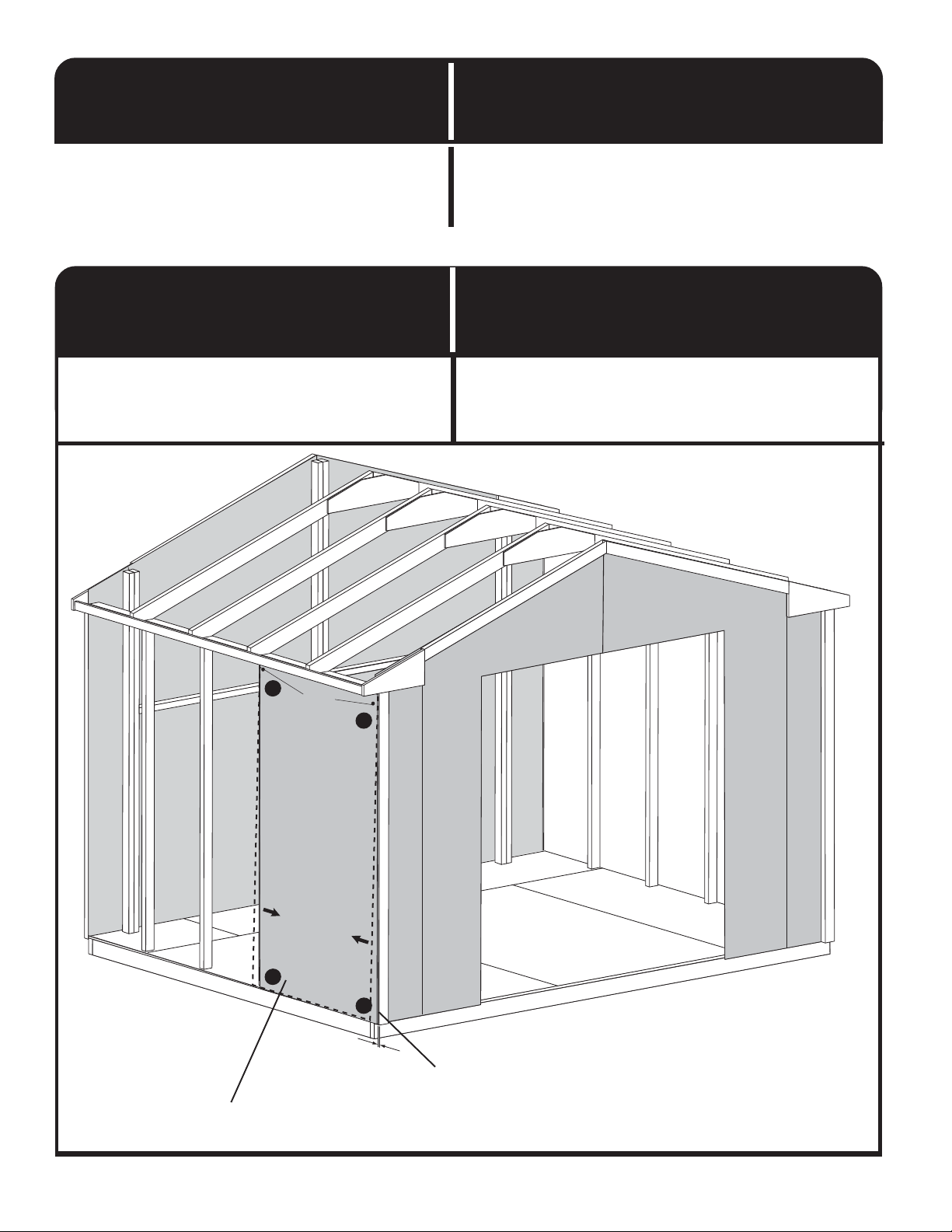
IMPORTANT!!!
Building Tip
IMPORTANTE!!!
Consejo
YOU MAY NEED T O RACK YOUR WALL PANELS
AND ROOF PANELS TO ENSURE SQU ARENESS
BEFORE COMPLETELY NAILING
Racking a Wall
When building walls, always apply panel to front of building first.
Position panel flush with top of wall frame and nail in upper corners as
shown. Rack wall square by moving lower end of wall panel right or left
until panel is flush with framing along left edge and secure with one nail
in each lower corner. Continue nailing as instructed.
ES PRECISO ALINEAR LOS PANELES DE LOS
MUROS Y DEL TECHO ANTES DE CLA V ARLOS
COMPLET AMENTE P ARA ASEGURAR LA ESCU ADRA.
Alineando un Muro
Al construir los muros, aplique siempre el panel al frente del edificio.
Posicione el panel nivelado con la parte superior de la estructura del
muro y clávelo en la esquina superior como en el dibujo. Alinee
nivelado el muro por mover el lado inferior a la derecha o a la izquierda
hasta que el panel esté nivelado con la estructura a lo largo del borde
izquierda. Fije con un clavo en cada esquina inferior.
2
Nail
Clavo
1
Rack for Squareness
Nivele para escuadrar
4
3
1/8" (3.2 cm)
Set panel back 1/8” (3.2 cm) from face of trim
lugar la panel espalda 1/8" (3.2 cm) del la cara del moldura
Nail corners 1 and 2, rack panel if necessary, nail 3 and 4
clavo esquinas 1 y 2, Alineando panel si hace falta, clavo 3 y 4
20
Page 21
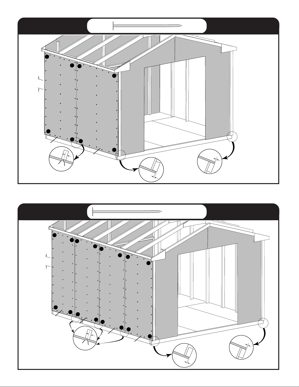
SIDE W ALL
2
8"
(20.3 cm)
4
F
3/4"
(1.9 cm)
2”(5 cm)
x128
MURO DELANTERO
x 40
10x9’-8-5/8”
1
2
1
1
3
4
3
3
F
1/8"
(3.2 cm)
SIDE W ALL
2
8"
(20.3 cm)
10x15’-8-5/8”
4
A
1
2
10x11’-8-5/8”
3
4
A
3/4"
(1.9 cm)
1/8"
(3.2 cm)
2”(5 cm)
x264
1
2
1
2
1
3
4
3
4
F
F
3
x 192 (10’x11’ 8-5/8”)
x 256 (10’x15’ 8-5/8”)
MURO DELANTERO
x 40
1/8"
(3.2 cm)
21
1/8"
(3.2 cm)
Page 22
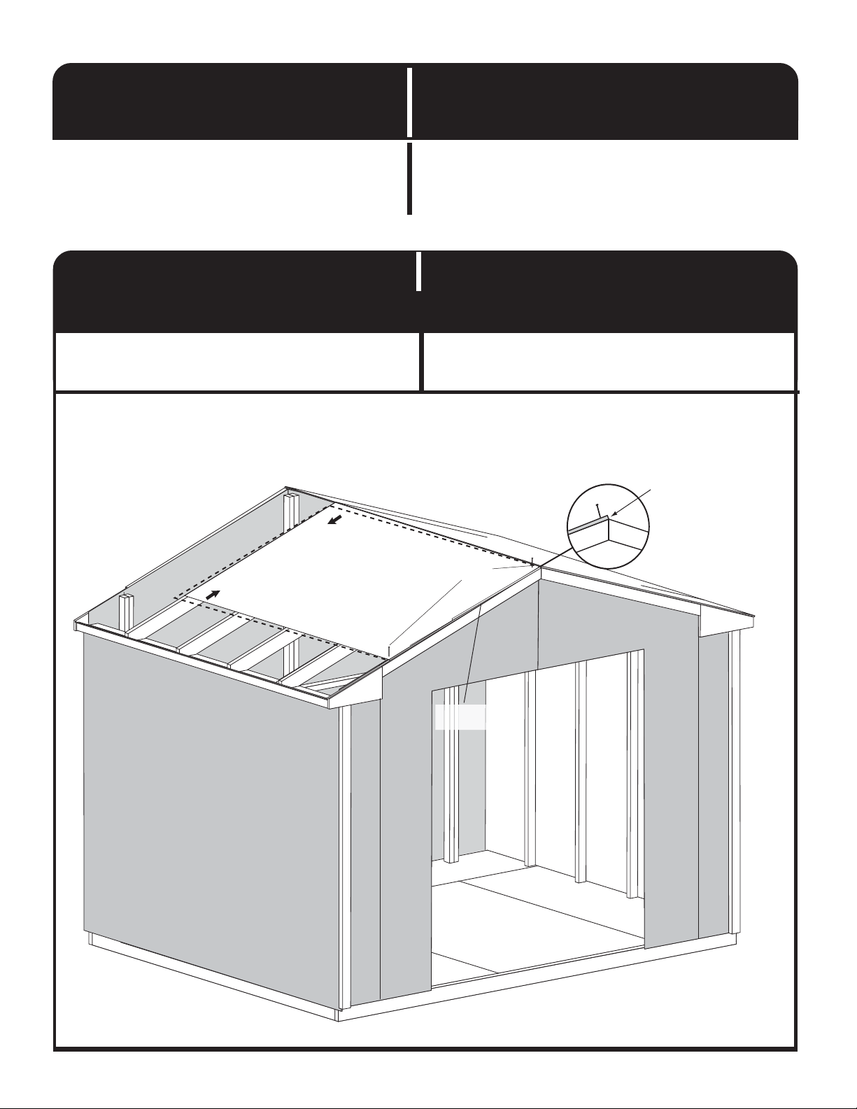
IMPORTANT!!!
Building Tip
IMPORTANTE!!!
Consejo
YOU MAY NEED T O RACK YOUR WALL PANELS
AND ROOF PANELS TO ENSURE SQU ARENESS
BEFORE COMPLETELY NAILING
Racking a Roof Alineando un techo
Position panel flush with outside front edge of rafter and nail in two
corners as shown. Rack panel square by moving opposite end up or down
until panel is flush along peak of rafters and secure with one nail in each
corner. Ensure spacing of center rafters and nail as instructed.
Rack for Squareness
Nivele para escuadrar
ES PRECISO ALINEAR LOS P ANELES DE LOS
MUROS Y DEL TECHO ANTES DE CLA V ARLOS
COMPLET AMENTE P ARA ASEGURAR LA ESCUADRA.
Posicione los paneles nivelados con el borde delantero exterior de la viga y clave
en las dos esquinas como en el dibujo. Alinee escuadra el panel por mover los
extremos opuestos arriba o abajo hasta que el panel esté nivelado a lo largo del
punto más alto de las vigas, y fíjelo con un clavo en cada esquina. Compruebe el
espacio de las vigas centrales y clave como indicado.
Flush with Rafter Peak
Nivelado con la parte más
alta de las vigas.
Nail
Clavo
22
Flush
Nivelado
Page 23
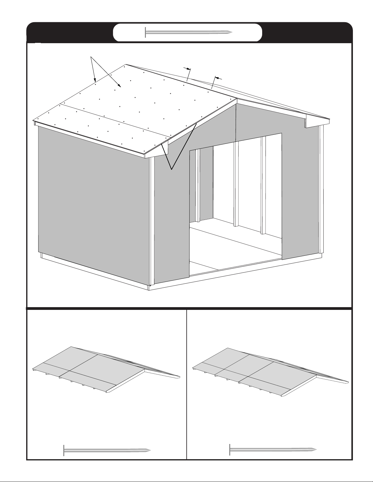
ROOF
Maintain truss dimension
Mantenga las dimensiones del armazón
Qx2
P x2
2”(5 cm)
Flush
Nivelado
x96
24" T ypical/Típico
(61 cm)
TECHO
x 40
10’x7’8-5/8” (305 x 235 cm) Shown / Indicado
10’x11’8-5/8” (305 x 357 cm)
O x2
Y x2
P x2
Q x2
x144
23
10’x15’8-5/8” (305 x 479 cm)
Y x2
O x2
Y x2
O x2
P x2
Q x2
x192
Page 24
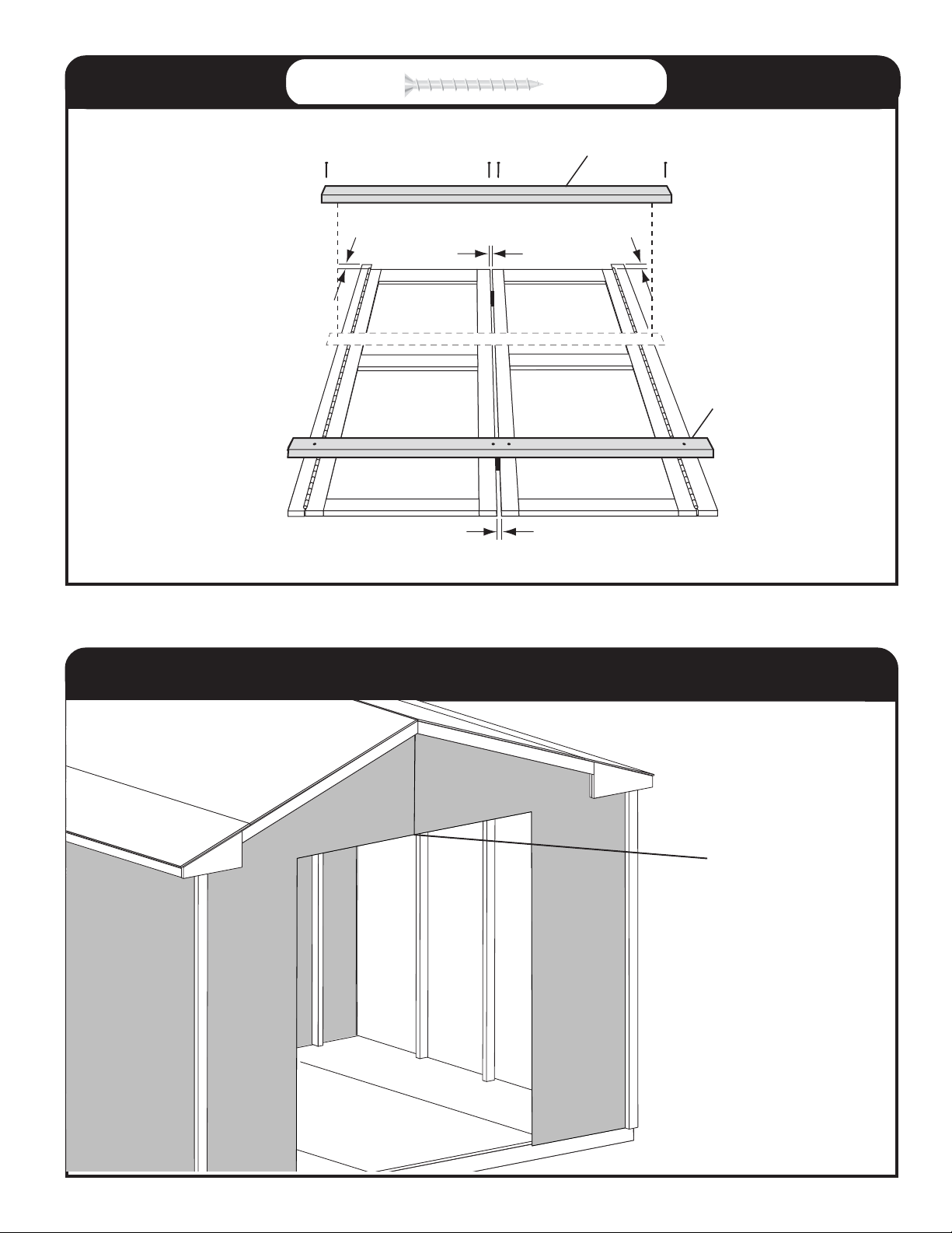
1-1/4”(3.2 cm)
DOOR PUERTA
x8
x 40
E
3/8” (1 cm) 3/8” (1 cm)
Top
7/16” (1.1 cm)
Parte
Superior
E
ML
7/16” (1.1 cm)
DOOR PUERTA
x 40
24
Place a center mark for door
location
Ponga un señal en el centro
para la puerta
Page 25
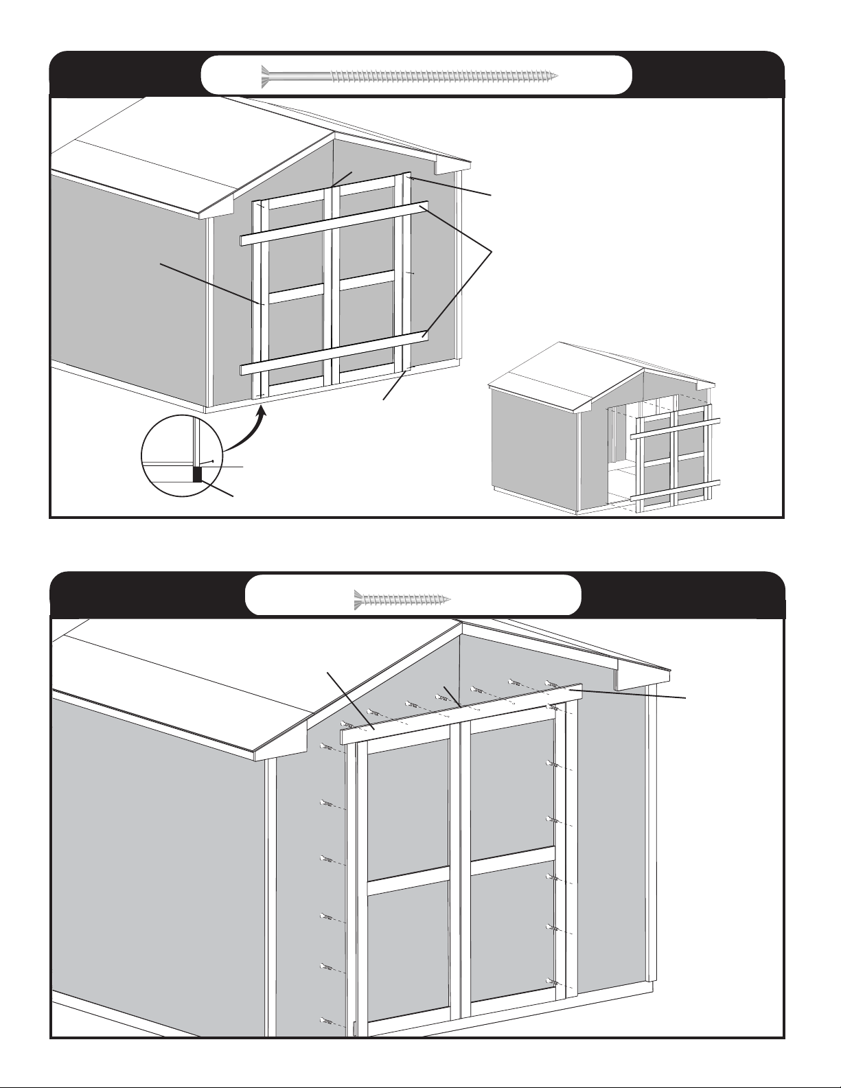
3”(7.6 cm)
DOOR PUERTA
Center
Centro
x6
Attach with 3” (7.6 cm) Screws first,
check doors to open properly
Fije con tornillos de 3" (7.6 cm) primero,
compruebe que las puertas abren bien
Screw into the wall support
tornillo en la pared apoyo
x 40
Remove center
screws after
installation is
complete
Quite los tornillos de
centro después de
que la instalación sea
completa
Bottom of door trim flush with bottom
of wall panel
Nivelado de la pared panel fondo con
Flush
Nivelado
Instale ayuda: Agregue el tablero libro mayor (no provisto en kit)
Install Tip: Add Ledger Board (Not supplied in kit)
el fondo del moldura de la puerta
Remove after doors are screwed.
Check doors to open properly
Quite después de fijar la puerta con
tornillos, compruebe que las puertas
abren bien
1”(5 cm)
DOOR PUERTA
x19
x 40
HJ
Center
Centro
25
Install 1” screw
from inside
instale 1” tornillo
desde dentro
Page 26
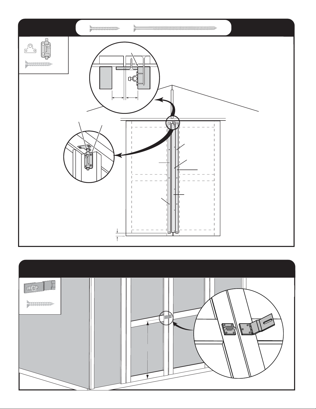
1”(2.5 cm)
DOOR PUERTA
x 6
3”(7.6 cm)
x 10
3/4” (1.9 cm) x6
x1
Drill 3/8"
(.9cm) Hole
Flush
Nivelado
Flush
Nivelado
1“
2.5cm1“2.5cm
E
(5) 3"
(7.6 cm)
Screws/tornillos
(5) 3"
(7.6 cm)
Screws/tornillos
(6) 1"
(2.5 cm)
Screws/tornillos
E
D
Inside of Door
Interior de la
Porte
2" (5cm)
DOOR PUERTA
x1
3/4” (1.9 cm) x7
36"
(91 cm)
26
Page 27
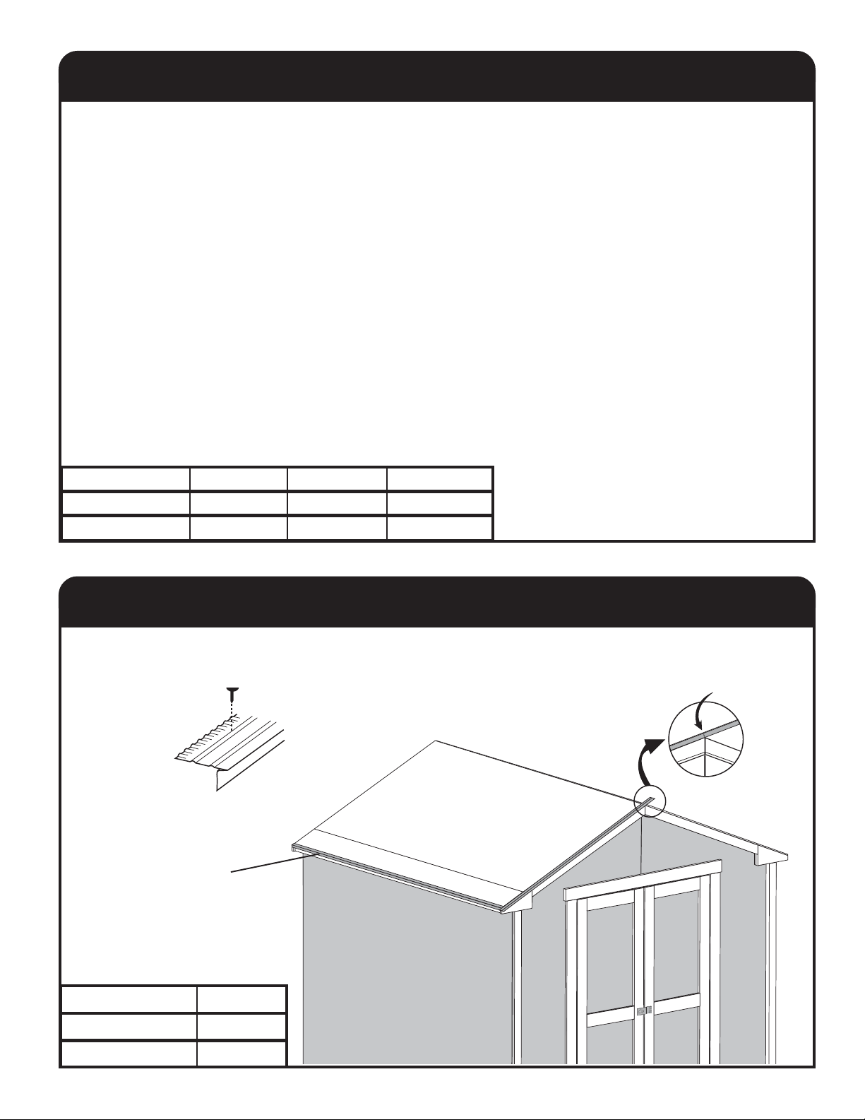
PAINT AND CAULK
(Not Included)
PINTURA Y MASILLADO
(No Incluidas)
Use Acrylic Latex Caulk that is paintable. Caulk at all
horizontal and vertical seams, between the Trim and
Walls, and all around the Door Trim.
Use a high quality exterior acrylic latex paint. When
painting your building, there are a few key areas that can
be easily overlooked that must be painted:
• Bottom edge of all siding and trim
• Inside of doors and all 4 edges
Note: Prime all un-primed exterior wood before painting
Building Size
Dimensiones del edificio
10’ x 7’8-5/8”
(305 x 235 cm)
10’ x 11’8-5/8”
(305 x 357 cm)
10’ x 15’8-5/8”
(305 x 479 cm)
Building Paint
Pintura del edificio
1-1/2 Gallons/
galones
2 Gallons/
galones
2-1/2 Gallons/
galones
Trim P aint
Pintura de moldura
1Quart/
cuartas
1Quart/
cuartas
1Quart/
cuartas
Use madillado acrílico de latex pintable. Masille todas
las costuras horizontals y verticales, entre la moldura y
los muros, y alrededor de la moldura de la puerta.
Use pintura acrílica de látex de lata calidad. Al pintar
su edificio, hay unas áreas claves que hay que pintar:
• Debajo de la moldura en las puertas.
• Debajo de la moldura de esquinas.
• Todo el exterior del edificio.
• Las partes interiors y superiors de las puertas y el
borde superior de la covertura.
Caulk
Masillado
2Tubes/
Tubos
2Tubes/
Tubos
2Tubes/
Tubos
DRIPEDGE
(Not Included)
Close up of dripedge
Vista del gotero
Side that hangs over
side No Nails
La parte que está
colgada sobre un lado.
No clavar.
Building Size
Dimensiones del edificio
10’ x 7’8-5/8”
(305 x 235 cm)
10’ x 11’8-5/8”
(305 x 357 cm)
10’ x 15’8-5/8”
(305 x 479 cm)
Dripedge
Gotero de borde
40’
50’
60’
GOTERO DE BORDE
(No Incluidas)
Snip bottom side of Dripedge and
Bend over to other side of Roof
Corte la parte inferior del gotero y
dóblela sobre el otro lado del techo
27
Page 28
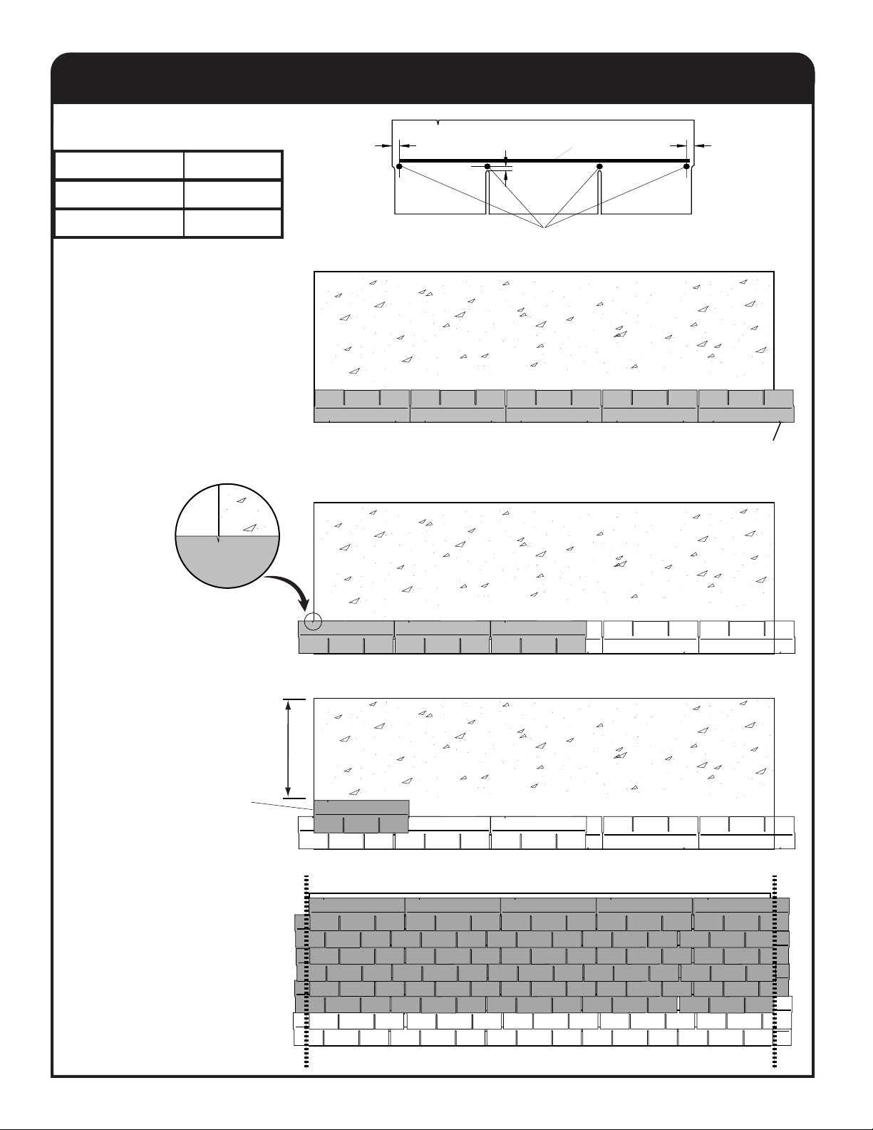
SHINGLES
(Not Included)
TEJAS
(No Incluidas)
x 40
Building Size Shingles Needed
Dimensiones del edificio
10’ x 7’8-5/8”
(305 x 235 cm)
10’ x 11’8-5/8”
(305 x 357 cm)
10’ x 15’8-5/8”
(305 x 479 cm)
Tejas necesarias
4 Bundles/bultos
6 Bundles/bultos
8 Bundles/bultos
Install first row backwards
Instale la primera fila al revés
Flush to dripedge
Nivelado al gotero
1"
(2.5 cm)
1/2"
(1.3 cm)
NAILS
CLAVOS
Clavos
Sealing Strip
1"
(2.5 cm)
Okay if Shingle Overlaps
Está bien si la teja
sobresale
Line up notch on top of Shingle with
edge of Roof to stagger the Shingles
Alinee el corte encima de la teja con el
borde del techo para escalonar las tejas.
Maintain same deminsion across
Mantenga la misma dimensión de
Flush to edge, stagger each row
Nivele al borde, escalone cada fila
Remove overhanging shingles
Quite tejas sobresalientes
un lado al otro
28
Page 29
SHINGLES
(Not Included)
TEJAS
(No Incluidas)
x 40
Ridge Cap
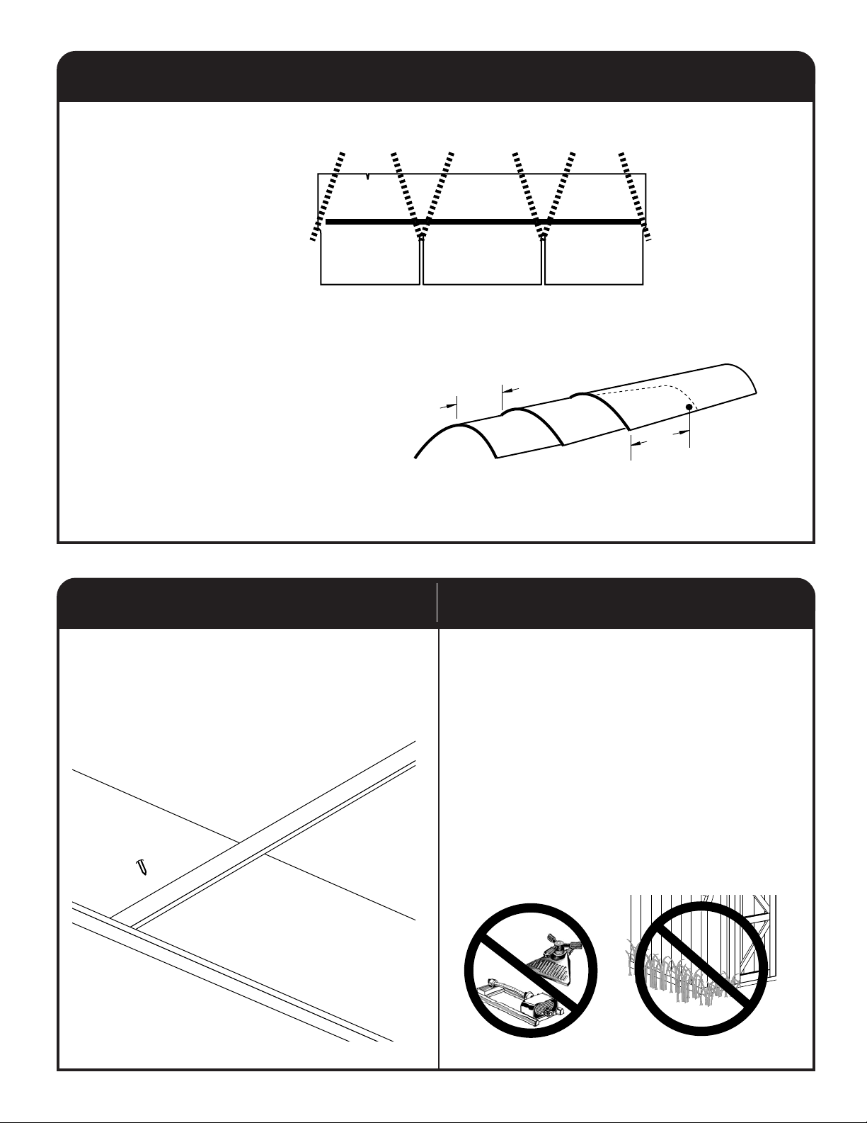
Cut Shingles into 3 pieces
Corte las tejas en tres partes
Apply pieces to ridge as shown
Fije las piezas a la cumbrera
como en el dibujo
Tapa de cumbrera
5-1/8"
(13 cm)
5-7/8"
(15 cm)
NAIL INSPECTION
NAIL INSPECTION
INSPECCIÓN DE CLAVOS
Check for protruding nails, pound any protruding
nails into the wood or cut them off flush.
Inspeccione para clavos sobresalientes; hinque
clavos sobresalientes en la madera or córtelos
nivelados con la madera.
REQUIRED MAINTENANCE
REQUIRED MAINTENANCE
x 40
MANTENIMENTO NECESARIO
Keep grass trimmed and away from building
Corte y quite la hierba cerca del edificio.
Keep Sprinklers away from building
No use rociadores cerca del edificio.
Repaint building as needed and in accordance
with paint manufacturer requirements
Pinte el edificio de nuevo cada dos años.
29
Page 30

Notes:
30
Page 31

Notes:
31
Page 32
WARRANTY
Backyard Storage Solutions, LLC warrants the following:
1. Every product is warranted from defects in workmanship and manufacturing for one year.
2. All hardware and metal components are warranted for two years.
3. Trim is warranted for 10 years.
4. Waferboard siding and sheathing is warranted for two years.
5. SmartSide™ siding is warranted for 10 years on all Marco series buildings and 15 years on all Premier Series buildings.
6. Timber series buildings’ siding and trim are warranted for 10 years.
7. Solar Shed windows are warranted for 1 year.
8. Cedar lumber is warranted for 15 years.
Backyard Storage Solutions, LLC will repair, replace or pay for the affected part. In no event shall Backyard Storage Solutions, LLC pay the cost of labor or installation or any other costs related thereto. All warranties
are from date of purchase. If a cash refund is paid on an affected part, it will be prorated from the date of purchase.
CONDITIONS
The warranty is effective only when:
1. The unit has been erected in accordance with the assembly instructions.
2. The unit has been properly shingled and painted or stained and reasonably and regularly maintained thereafter.
3. The failure occurs when the unit is owned by the original purchaser.
4. Backyard Storage Solutions, LLC has received the warranty registration card within thirty (30) days of purchase and notification of the failure in writing within the warranty period specified above.
5. Backyard Storage Solutions, LLC has had reasonable opportunity during the sixty (60) days following receipt of notification to inspect and verify the failure prior to commencement of any repair work.
REQUIREMENTS
Storage Buildings & Playhouses
To validate your warranty, it is necessary to properly maintain your Backyard Storage Solutions, LLC unit; shingle the roof and paint or solid-colored stain the siding using 100% acrylic latex exterior product with a
minimum of two (2) coats within thirty (30) days of assembly; caulk above all doors and all horizontal and vertical trim boards; paint and seal all exposed edges, sides and faces of SmartSide™ and waferboard siding to
include all exterior walls and all sides and all edges of doors.
Gazebos, Pergols & Timber Buildings
To validate your warranty, it is necessary to properly maintain your Backyard Storage Solutions, LLC unit. This includes treating all of the exposed cedar and pine surfaces on your gazebo or timber building with an
exterior grade wood preservative, an exterior oil-based semi-transparent stain, an acrylic latex exterior paint or an acrylic latex solid color exterior stain within 30 days of assembly and as needed thereafter to maintain
your warranty.
Keep vegetation trimmed away from building and make sure siding panels and trim do not come in contact with masonry or cement. The minimum ground clearance for siding must be one half inch (½ inch) from
concrete slab or two and one half inches (2 ½”) from the ground when building is erected or constructed on a treated wood floor kit. Water from sprinklers must be kept off unit. In no event will Backyard S
Solutions, LLC be responsible for any indirect, incidental, consequential or special damages nor for failure(s) that are caused by events, acts or omissions beyond our control including, but not limited to, misuse or
improper assembly, improper maintenance (which eventually leads to rot or decay) and acts of God. Backyard Storage Solutions, LLC will not be held responsible for any labor costs incurred to construct your unit.
This warranty gives you certain specific rights that vary from state to state.
CLAIM PROCEDURE
To make a claim under this warranty, you can either call (800) 437-0784 or prepare a letter. Please have ready the information below when you call or include the information when writing:
1. The model and size of the product.
2. A list of the part(s) for which the claim is made.
3. Proof of purchase of the Backyard Storage Solutions, LLC item, as shown on the original invoice.
4. Run code, as listed on the yellow warranty card enclosed in the product package.
Mail the above information to:
Backyard Storage Solutions, LLC
Attn: Customer Service
1000 Ternes
Monroe, MI 48162
*WARRANTY TERMS MAY VARY OUTSIDE THE U.S.A.
IMPORTANT: This is your warranty certificate.
Please complete and mail your warranty card to properly validate your warranty. ldr: 12/15/06
Limited Conditional
Warranty *
torage
Backyard Storage Solutions, LLC le garantiza a Ud. que:
1. Cada producto no tiene defecto de mano de obra ni de manufactura por un período de un año.
2. La ferretería y los componenetes de metal están garantizados por dos años.
3. La moldura está garantizada por 10 años.
4. La covertura y el entablado están garantizados por dos años.
5. La covertura SmartSide™ está garantizada por 10 años para los edificios Marco Series, y por 15 años para los edificios Premier Series.
6. La covertura y la moldura de los edificios Timber Series están garantizadas por 10 años.
7. Las ventanas del Solar Shed están garantizadas por un año.
8. La madera de cedro está garantizada por 15 años.
Backyard Storage Solutions, LLC reparará, cambiará o pagará por la pieza afectada. En ningún casa pagará Backyard Storage Solutions, LLC los gastos de instalación o trabajo manual, o cualquieres otros gastos
relacionados a eso.
Condiciones
Esta garantía es válida solo cuando:
1. La unidad ha sido construida según las instrucciones.
2. La unidad ha sido cubierta de tejas y pintada de manera correcta y mantenida regularmente.
3. El defecto ocurre mientras la unidad está en la posesión del comprador original.
4. Backyard Storage Solutions, LLC ha recibido la tajeta de garantía del producto en el plazo de 30 (treinta) días después de comprar la unidad y después de la notificación del defecto por escrito, duranteel
período de vigencia de la garantía especificada arriba.
5. Backyard Storage Solutions, LLC ha tenido una oportunidad razonable, durante los sesenta (60) días después de haber recibido la notificación, para inspeccionar y averiguar la falla o el defecto antes de
comenzar cualquiera reparación.
Requisitos
Cobertizos de almanacemiento y Casitas de niños
Para dar validez a la garantía, es necesario mantener bien su unidad de Backyard Storage Solutions, LLC: cubrir con tejas el techo, pintar la covertura con un producto 100% de acrílico
y de látex para exteriores, usando dos manos de pintura o tinte, como mínimo, en el plazo de treinta (30) días después de la construcción; masille arriba de todas las puertas y todos los paneles de moldura
horizontales y verticales; pinte y selle todos los bordes dispuestos al exterior, los lados y las fachadas del la covertura SmartSide™ y plano, incluyendo todos los muros exteriores y los lados y bordes de las puertas.
Belvederes, Pergolas y Edificios de Madera
Para dar validez a la garantía, es necesario mantener bien su inidad. Eso incluye tratar con un preservativo todos los superficies de cedro y de pino duspuestos al exterior, usando una preservativo para madera, un
tinte de aceite semitransparente para exteriores, pintura acrílica de látex para exteriores, o un tinte acrílico de látex de un solo color, en el plazo de treinta (30) días después de construir el edificio, y luego como sea
necesario.
Mantenga corta toda clase de vegetación cerca del edificio y asegúrese que la covertura y la moldura no toquen ningúna obra de albañería o el cemento. El margen mínimo entre el suelo y la covertura debe de ser
media pulgada (1/2"), con un base de concreto; dos pulgadas y media (2 1/2") cuando se construye el edificio sobre un base de madera (usando un equipo de madera tratada). No se deben usar rociadores cerca de
la unidad. En ningún caso será responsable Backyard Storage Solutions, LLC de daños especiales, incidentales, consiguientes o indirectos, ni de fallas causadas por sucesos, hechos u omisiones fuera de nuestro
control; eso incluye, pero no está limitado a: el misuso; la construcción incorrecta; cuidado incorrecto (el cual causa, eventualmente, la putrefacción o la descomposición ) y acciones de la naturaleza. Backyard
Storage Solutions, LLC no será responsable de ningún gasto de instalación incurrido durante la construcción de la unidad. Esta garantía le de a Ud. ciertos derechos específicos que varían de estado a estado.
Para hacer una reclamación:
Para hacer una reclamación baja esta garantía, llame al (800) 437-0784) o escriba una carta. Favor de tener la siguiente información al llamarnos, o incluirla al escrbirnos:
1. El modelo y el tamaño del producto.
2. Una lista de las piezas por las cuales hace Ud. la reclamación.
3. Prueba de compra del producto, como se muestra en la factura original.
4. (Run code) escrita en la tarjeta amarilla de garantía incluida con el producto.
Envíe la información a:
Backyard Storage Solutions, LLC
Attn: Customer Service
1000 Ternes
Monroe, MI 48162
USA
*LAS CONDICIOINES DE LA GARANTIA PUEDEN VARIAR FUERA DE ESTADOS UNIDOS
Favor de llenar completamente y enviar la tarjeta de garantía para dar validez a la garantía.
IMPORTANTE: Esta página es su certificado de garantía.
Garantía Limitada
Condicional *
ldr: 12/15/06
 Loading...