

Page 1
WESTON
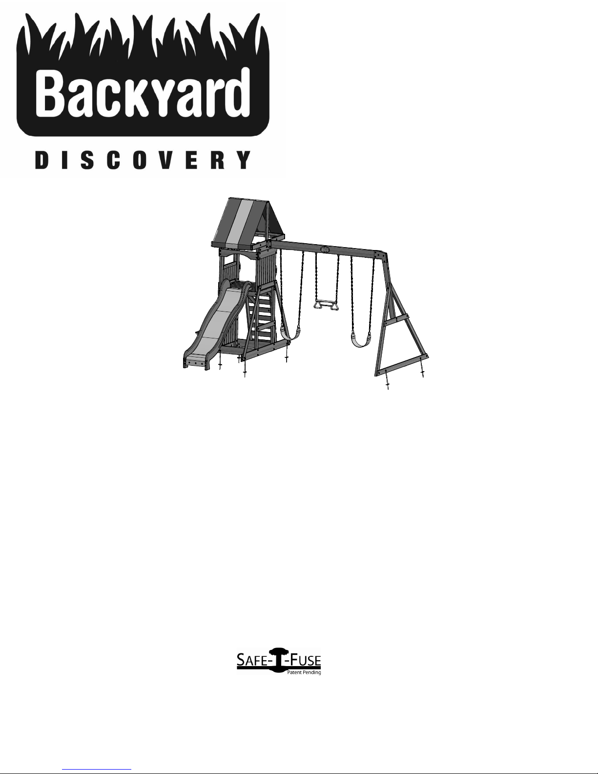
Wooden Swing Set
Model: # 65113
•• Owner's Manual
•• Frequently Asked Questions
•• Assembly Instructions
•• Warranty Information
Manufacturer: Backyard Discovery
3001 North Rouse
Pittsburg, KS 66762
1-800-856-4445
Register your new swing set on-line @ www.swingsetsonline.com
(you will also find any updates on assembly instructions and
information to order replacement parts)
Features the fastening system.
Save this assembly manual for future reference in the event that
you need to order replacement parts.
INS-65113-A-WESTON-Eng 10/08/12
Made in China
Page 2
STOP
PARE
Missing A Part?
CALL US BEFORE GOING
BACK TO THE STORE!
The store where you made your purchase
does not stock parts for this item.
If you have assembly questions or if you need parts,
whether they are missing
Call Toll-Free Help Line or visit www.swingsetsonline.com
¡LLÁMENOS ANTES DE REGRESAR A LA TIENDA!
La tienda donde realizó la compra no almacena piezas de este producto.
Si tiene preguntas sobre el ensamblaje o si necesita piezas debido a que
faltan o están dañadas
llame gratis a la línea de ayuda
1-800-856-4445
or damaged
PLEASE READ THIS BEFORE STARTING ASSEMBLY
POR FAVOR LEA ESTAS INSTRUCCIONES ANTES DE COMENZAR EL ENSAMBLAJE
• READ THE ASSEMBLY MANUAL COMPLETELY, PAYING SPECIAL ATTENTION TO THE IMPORTANT TIPS AND
SAFETY INFORMATION.
• AFTER YOU HAVE READ THE ASSEMBLY MANUAL, YOU WILL BE ABLE TO DECIDE IF YOU NEED PROFESSIONAL
HELP TO COMPLETE THE ASSEMBLY OF THE STRUCTURE.
• SEPARATE AND IDENTIFY ALL PARTS TO MAKE SURE THAT YOU HAVE ALL OF THE PARTS LISTED.
• IF YOU CAN’T FIND ALL OF THE PARTS, CHECK THE PACKING MATERIAL. SMALL PARTS MAY HAVE FALLEN INTO IT
DURING SHIPMENT.
• IF YOU HAVE PROBLEMS WITH THE ASSEMBLY OR IF ANY PART IS MISSING OR DAMAGED, PLEASE CALL THE
HELP LINE
• LEA EL MANUAL DE ENSAMBLAJE COMPLETAMENTE, PRESTANDO ESPECIAL ATENCIÓN A LOS CONSEJOS ÚTILES
IMPORTANTES Y A LA INFORMACIÓN SOBRE SEGURIDAD.
• DESPUÉS DE QUE HAYA LEÍDO EL MANUAL DE ENSAMBLAJE, PODRÁ DECIDIR SI NECESITA AYUDA PROFESIONAL
PARA EFECTUAR EL ENSAMBLAJE DE LA ESTRUCTURA.
• SEPARE E IDENTIFIQUE TODAS LAS PIEZAS PARA COMPROBAR QUE DISPONE DE TODAS LAS PARTES INDICADAS.
• SI NO PUEDE ENCONTRAR TODAS LAS PIEZAS, REVISE EL MATERIAL DE EMPAQUE. ES POSIBLE QUE ALGUNAS
PIEZAS PEQUEÑAS PUEDAN HABERSE CAÍDO ALLÍ DURANTE EL ENVÍO.
• MANTÉNGASE ALEJADO DE LOS NIÑOS MENORES A LA EDAD RECOMENDADA.
• SI TIENE PROBLEMAS CON EL ENSAMBLAJE O SI ALGUNA PIEZA FALTA O ESTÁ DAÑADA, LLAME A LA LÍNEA DE
AYUDA AL 1-800-856-4445 O VISITE www.swingsetsonline.com
1-800-856-4445 OR VISIT www.swingsetsonline.com
PLEASE HAVE THE FOLLOWING INFORMATION WHEN YOU MAKE YOUR CALL:
1 – MODEL NUMBER OF THE PRODUCT LOCATED ON THE FRONT OF THE ASSEMBLY MANUAL
2 – DESRIPTION OF THE PART FROM THE PARTS LIST
POR FAVOR TENGA VISIBLE LA SIGUIENTE INFORMACIÓN CUANDO LLAME:
1 - NÚMERO DE MODELO DEL PRODUCTO QUE SE ENCUENTRA UBICADO AL FRENTE DEL MANUAL
DE ENSAMBLAJE
2 - DESCRIPCIÓN DE LA PIEZA QUE SE ENCUENTRA EN LA LISTA DE PIEZAS
Page 3
Owner’s Manual Play Set
Dear Customer:
Please read entire booklet completely before beginning the assembly process.
Equipment is recommended for use by children 3 to 10 years of age. Structures are not intended for public use.
The Company does not warranty any of its residential structures subjected to commercial use such as:
Daycare, Preschool, Nursery School, Recreational Park, or any similar Commercial Application.
WARNING: This Symbol points out important safety instructions which, if not followed, could endanger
the personal safety of yourself and your children and/or damage your property. You MUST read and
follow all instructions in this manual before attempting to use this playcenter.
WARNING: Children must NOT use this playcenter until unit has been completely assembled
and inspected by an adult to insure set has been properly installed and anchored.
Please follow all recommendations below. Failure to do so may result in the warranty being void and/or safety
violations that could result in serious injury. This manual contains helpful information concerning Assembly
Preparation, Installation Procedure, and Required Maintenance. Always keep the safety of your children in mind as
your play structure is being built and as your children play on the set. Before your children play on the set please
review the Operation Instructions with them to help ensure their safety
PLEASE RETAIN THESE INSTRUCTIONS FOR FUTURE REFERENCE. KEEP THEM IN A SAFE PLACE WHERE YOU CAN
REFER TO THEM AS NEEDED. IN ORDER TO PROVIDE YOU WITH THE MOST EFFICIENT SERVICE, IT IS REQUIRED THAT
YOU PROVIDE US WITH THE PART NUMBERS WHEN ORDERING PARTS.
.
For Your Records:
Please take time and fill out the information below. This information will be needed for warranty issues.
Where Purchased: ____________________
Date of Purchase: ____________________
Installation Date: _____________________
Installed by: _________________________
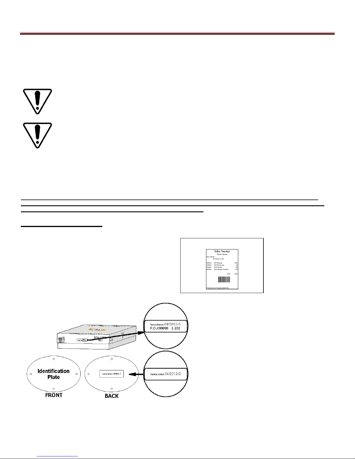
Tracking Number: ____________________
Staple Receipt Here
Tracking Number Reference Label
Tracking ID number on the carton and back of the ID plate are included for tracking purposes
associated with warranty claims.
Rev5/09/12
Page 4

Owner’s Manual Play Set
Please refer to the Assembly section of the Assembly Manual for Maximum Fall Height.
Positioning Your Playcenter
1. The Playcenter is designed to be installed on a level surface by an Adult with an Adult
helper. Place in a flat area of your yard to minimize ground preparation.
2. Choose a level location for the equipment. This can reduce the likelihood of the play set
tipping over and loose-fill surfacing material washing away during heavy rains.
3. Place the equipment not less than 6 ft (1.8 m) from any structure or obstruction such as a
fence, garage, house, overhanging branches, laundry lines, or electrical wires.
4. Provide enough room so that the children can use the equipment safely. For example, for
structures with multiple play activities, a slide should not exit in front of a swing.
5. It is a good idea to place your Playcenter in an area that is convenient for adults to watch
children at play.
6. Create a site free of obstacles that could cause injuries – such as low overhanging tree
branches, overhead wires, tree stumps and/or roots, large rocks, bricks and concrete.
Additional suggestions in the Suggested Playground Surfacing Section.
7. Do not build your playset on top of surfacing material.
8. Locate bare metal platforms and slides out of direct sunlight to reduce the likelihood of serious
burns. A slide that faces north will receive the least direct sunlight.
9. Separate active and quiet activities from each other. For example, locate sandboxes away
from swings or use a guardrail or barrier to separate the sandbox from the movement of the
swings.
Suggested Playground Surfacing
Do not install home playground equipment over concrete, asphalt, packed earth, grass, carpet,
or any other hard surface. A fall onto a hard surface can result in serious injury to the
equipment user.
Do not install loose fill surfacing over hard surfaces such as concrete or asphalt.
Shredded bark mulch, wood chips, fine sand and fine gravel, are added as shock absorbing
materials after assembly. If used properly these materials can absorb some of the impact of a
child’s fall.
All surface material should extend a minimum of 6 feet in all directions around the play area.
Do not apply playground surfacing until after the unit is completely constructed. Playset should
not be built on top of surfacing.
Use containment, such as digging out around the perimeter and/or lining the perimeter with
landscape edging.
Installations of rubber tiles or poured-in-place surfaces (other than loose-fill materials)
generally require a professional and are not “do-it-yourself” projects.
Shall use Playground Surfacing Materials (other than loose-fill material) which comply with the
safety standard ASTM F1292 Standard Specification of Impact Attenuation of Surfacing
Materials within the Use Zone of Playground Equipment.
Rev5/09/12
Page 5
Owner’s Manual Play Set
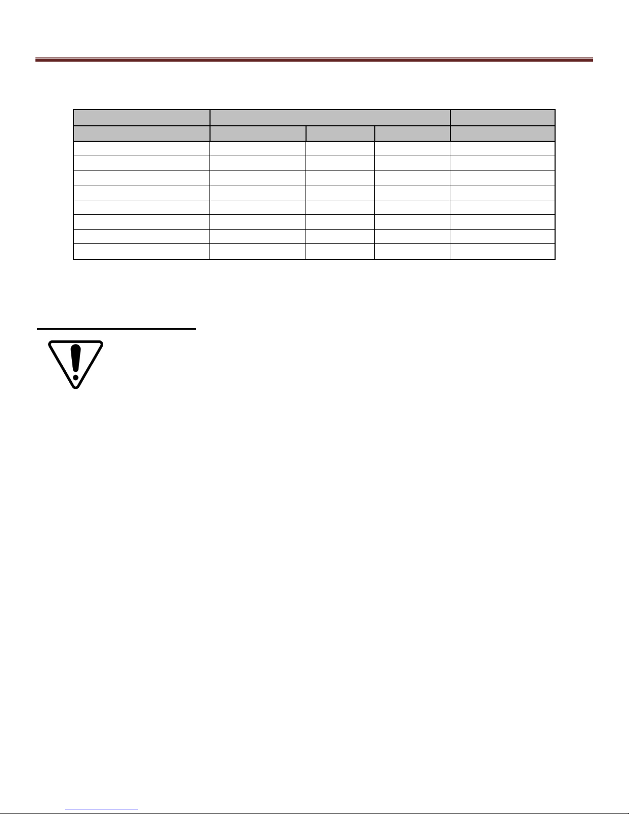
The following chart explains the fall height in feet from which a life threatening head injury
would not be expected
Critical Heights in feet (m) of Tested Materials
Material Uncompressed Depth Compressed Depth
6" (152mm) 9" (228mm) 12" (304mm) to 9" (228mm)
Wood Chips 7' (2.13m) 10' (3.05m) 11' (3.35m) 10' (3.05m)
Double-Shredded bark mulch
Engineered Wood Fibers 6' (1.83m) 7' (2.13m) >12' (3.66m) 6' (1.83m)
Fine Sand 5' (1.52m) 5' (1.52m) 9' (2.74m) 5' (1.52m)
Coarse Sand 5' (1.52m) 5' (1.52m) 6' (1.83m) 4' (1.22m)
Fine Gravel 5' (1.52m) 7' (2.13m) 10' (3.05m) 6' (1.83m)
Medium Gravel 5' (1.52m) 5' (1.52m) 6' (1.83m) 5' (1.52m)
Shredded Tires* 10-12' (3.0-3.6m) N/A N/A N/A
*This data is from tests conducted by independent testing laboratories on a 6-inch depth of uncompressed shredded tire samples produced by four manufacturers. The tests
reported critical heights, which varied from 10 feet to greater than 12 feet. It is recommended that persons seeking to install shredded tires as a protective surface request test
Operating Instructions:
data from the supplier showing the critical height of the material when it was tested in accordance with ASTM F1292.
NOTE: Your children’s safety is our #1 concern. Observing the following statements
and warnings reduces the likelihood of serious or fatal injury. Please review these
safety rules regularly with your children.
1. This Playcenter is designed for specific number of occupants whose combined weight should
not exceed a designated weight on the elevated floor or the swing area, the total Unit capacity
is outlined in the Basic Setup Dimensions section of instruction manual. The maximum fall
height and recommended play area is also available in the Basic Setup Dimensions section of
the manual for the specific unit.
2. On-site adult supervision is required.
3. Instruct children not to walk close to, in front of, behind, or between moving swings or other
moving playground equipment.
4. Instruct children to sit in and never stand on swings
5. Instruct children not to twist the chains and ropes and not to loop them over the top support
bar, since this may reduce the strength of the chain or rope.
6. Instruct children not to jump from swings or other playground equipment in motion.
7. Instruct children to not to push empty seats. The seat may hit them and cause serious injury.
8. Instruct and teach children to sit in the center of the swings with their full weight on the seats.
9. Instruct children not to use the equipment in a manner other than intended.
10. Instruct children to always go down slides feet first. Never slide head first.
11. Instruct children to look before they slide to make sure no one is at the bottom.
12. Instruct children to never run up a slide, as this increases their chances of falling.
13. The parents should dress children appropriately. (Examples would include the use of wellfitting shoes and the avoidance of ponchos, scarfs, and other loose-fitting clothing that is
potentially hazardous while using equipment).
14. Instruct children not to climb when the equipment is wet.
15. Instruct children to never jump from a fort deck. They should always use the ladder, ramp or
slide.
16. Instruct children to never crawl or walk across the top of monkey bars.
17. Instruct children to never crawl on top of a fort roof.
6' (1.83m) 10' (3.05m) 11' (3.35m) 7' (2.13m)
Rev5/09/12
Page 6

Owner’s Manual Play Set
18. Verify that any suspended climbing ropes, chain, or cable are secured at both ends and that
they cannot be looped back on it.
19. Instruct children not to attach items to the playground equipment that are not specifically
designed for use with the equipment, such as, but not limited to, jump ropes, clothesline, pet
leashes, cables and chain as they may cause a strangulation hazard.
20. Instruct children to never wrap their legs around swing chain.
21. Instruct children to never slide down the swing chain.
22. Instruct children to remove their bike or other sports helmet before playing on playground
equipment.
Maintenance Instructions:
At the beginning of each play season:
• Tighten all hardware.
• Lubricate all metallic moving parts per manufacturer’s instructions.
• Check all protective coverings on bolts, pipes, edges, and corners. Replace if they are loose,
cracked, or missing.
• Check all moving parts including swing seats, ropes, cables, and chains for wear, rust, or
other deterioration. Replace as needed.
• Check metal parts for rust. If found, sand and repaint using a non Lead-based paint meeting
the requirements of 16 CFR 1303.
• Check all wood members for deterioration and splinters. Sand down splinters and replace
deteriorating wood members.
• Reinstall any plastic parts, such as swing seats or any other items that were removed for the
cold season.
• Rake and check depth of loose fill protective surfacing materials to prevent compaction and
to maintain appropriate depth. Replace as necessary.
Twice a month during play season:
• Tighten all hardware.
• Check all protective coverings on bolts, pipes, edges, and corners. Replace if they are loose,
cracked, or missing.
• Rake and check depth of loose fill protective surfacing materials to prevent compaction and
to maintain appropriate depth. Replace as necessary.
• Once a month during play season.
• Lubricate all metallic moving parts per manufacturer’s instructions.
• Check all moving parts including swing seats, ropes, cables, and chains for wear, rust, or
other deterioration. Replace as needed.
At the end of each play season or when the temperature drops below 32° F:
• Remove plastic swing seats and other items as specified by the manufacturer and take
indoors or do not use.
• Rake and check depth of loose fill protective surfacing materials to prevent compaction and
to maintain appropriate depth. Replace as necessary.
Rev5/09/12
Page 7

Owner’s Manual Play Set
Additional Maintenance:
• Check the swing beam and hardware every two weeks due to wood expansion and
contraction. It is particularly important that this procedure be followed at the beginning of each
season.
• Inspect wood parts monthly. The grain of the wood sometimes will lift in the dry season
causing splinters to appear. Light sand may be necessary to maintain a safe playing
environment. Treat your playset with stain regularly, to help prevent severe checking/splitting
and other weather damage.
• A waterbourne transparent stain has been applied to your playset. This is done for color only.
Once or twice a year, depending on your climate conditions, you must apply some type of
protection (sealant) to the wood of your unit. Prior to the application of sealant, lightly sand any
“rough” spots on your playset. Please not this is a requirement of your warranty.
• Assembling and maintaining the playset on a level location is very important. As your children
play, your playset will slowly dig its way into the soil, and it is very important that it settles
evenly. Make sure the playset is level and true one each year or at the beginning of each play
season.
Disposal Instructions:
When the Playcenter use is no longer desired, it should be disassembled and disposed of in such a
way that no unreasonable hazards will exist at the time the unit is discarded.
Third Party Assembly:
Customer may, in their sole discretion, elect to use a third party person or service to assemble this
product. Backyard Discovery assumes no responsibility or liability for any charge incurred by the
Customer for any assembly services’.
Please see our warranty for more information about damaged and missing part replacement
coverage. Backyard Discovery will not reimburse Customer for the price of parts purchased.
Rev5/09/12
Page 8

Owner’s Manual Play Set
APPENDIX A
Information on Playground Surfacing Materials:
The following information is from the United States Consumer Product Safety Commission’s
Information Sheet for playground surfacing material; also see the following website for additional
information: www.cpsc.gov/cpscpub/pubs/323.html.
X3. SECTION 4 OF THE CONSUMER PRODUCT SAFETY COMMISSION’S OUTDOOR HOME PLAYGROUND SAFETY
X3.1 Select Protective Surfacing—One of the most important things you can do to reduce the likelihood of
serious head injuries is to install shock-absorbing protective surfacing under and around your play equipment. The
protective surfacing should be applied to a depth that is suitable for the equipment height in accordance with ASTM
Specification F 1292. There are different types of surfacing to choose from; whichever product you select, follow these
guidelines:
X3.1.1 Loose-Fill Materials:
X3.1.1.1 Maintain a minimum depth of 9 inches of loose-fill materials such as wood mulch/chips, engineered
wood fiber (EWF), or shredded/recycled rubber mulch for equipment up to 8 feet high; and 9 inches of sand or pea
gravel for equipment up to 5 feet high. NOTE: An initial fill level of 12 inches will compress to about a 9-inch depth of
surfacing overtime. The surfacing will also compact, displace, and settle, and should be periodically refilled to maintain at
least a 9-inch depth.
X3.1.2 Use a minimum of 6 inches of protective surfacing for play equipment less than 4 feet in height. If
maintained properly, this should be adequate. (At depths less than 6 inches, the protective material is too easily
displaced or compacted.) NOTE: Do not install home playground equipment over concrete, asphalt, or any other hard
surface. A fall onto a hard surface can result in serious injury to the equipment user. Grass and dirt are not considered
protective surfacing because wear and environmental factors can reduce their shock absorbing effectiveness. Carpeting
and thin mats are generally not adequate protective surfacing. Ground level equipment such as a sandbox, activity wall,
playhouse or other equipment that has no elevated play surface – does not need any protective surfacing.
X3.1.3 Use containment, such as digging out around the perimeter and/or lining the perimeter with landscape
edging. Don’t forget to account for water drainage.
X3.1.3.1 Check and maintain the depth of the loose-fill surfacing material. To maintain the right amount of loose-
fill materials, mark the correct level on play equipment support posts. That way you can easily see when to replenish
and/or redistribute the surfacing.
X3.1.3.2 Do not install loose-fill surfacing over hard surfaces such as concrete or asphalt.
X3.1.4 Poured-In-Place Surfaces or Pre-Manufactured Rubber Tiles — You may be interested in using surfacing
other than loose-fill materials – like rubber tiles or poured-in-place surfaces.
X3.1.4.1 Installations of these surfaces generally require a professional and are not “do-it-yourself” projects.
X3.1.4.2 Review surface specification before purchasing this type of surfacing. Ask the installer/manufacturer for
a report showing that the product has been tested to the following safety standard: ASTM F 1292 Standard Specification
for Impact Attenuation of Surfacing Materials within the Use Zone of Playground Equipment. This report should show the
specific height for which the surface is intended to protect against serious head injury. This height should be equal to or
greater than the fall height – vertical distance between a designated play surface (elevated surface for standing, sitting, or
climbing) and the protective surfacing below – of your play equipment.
X3.1.4.3 Check the protective surfacing frequently for wear.
X3.1.5 Placement — Proper placement and maintenance of protective surfacing is essential. Be sure to:
X3.1.5.1 Extend surfacing at least 6 feet from the equipment in all directions.
X3.1.5.2 For to-fro swings, extend protective surfacing in front of and behind the swing to a distance equal to
twice the height of the top bar from which the swing is suspended.
Information Guide” and “Handbook for Public Playground Safety.” Copies of these reports can be obtained by sending a
postcard to the: Office of Public Affairs, U.S. Consumer Product Safety Commission, Washington, D.C., 20207 or call the
toll-free hotline: 1-800-638-2772.
9
This information has been extracted from the CPSC publications “Playground Surfacing — Technical
HANDBOOK
9
Rev5/09/12
Page 9

Owner’s Manual Play Set
The American Society for Testing and Materials takes no position respecting the validity of any parent right
asserted in connection with any item mentioned in this standard. Users of this standard are expressly advised that
determination of the validity of any such parent rights, and the risk of infringement of such rights, are entirely their own
responsibility.
The standard is subject to revision at any time by the responsible technical committee and must be reviewed
every five years and if not revised, either approved or withdrawn. Your comments are invited either for revision of this
standard or for additional standards and should be addressed to ASTM Headquarters. Your comments will receive
careful consideration at a meeting of the responsible technical committee, which you may attend. If you feel that your
comments have not received a fair hearing you should make your views known to the ASTM Committee on Standards.
100 Barr Harbor Drive, West Conshohocken, PA 19428.
Rev5/09/12
Page 10

Play Set Assembly Manual FAQs:
1. Does the area for the playset need to be level?
Yes. Backyard Discovery recommends the playset be positioned on a flat level area for
maximum safety and durability. The stakes provided should be used to secure it firmly to the
ground.
2. What size area is recommended for the playset?
Backyard Discovery recommends at least a 6’ (six foot) perimeter around and above the playset
for maximum safety.
3. What age range is appropriate for the playsets?
Backyard Discovery playsets are recommended for children ages 3 – 10 years.
4. Is the wood treated with chemicals?
Backyard Discovery uses 100% Chinese Cedar wood which is naturally bug resistant, decay
and rot resistant. To help ensure your child’s safety, our wood is completely chemical free and
we do not use pressure-treated wood. The stain we use is a top coat using a water-based
product that is for appearance only.
5. How often should the playset be stained?
Backyard Discovery recommends the playset be stained once each year. A water or oil based
stain can be used at the customer’s discretion.
6. Why does it seem that my swing set is developing cracks?
Wood is a natural material; no two pieces are exactly alike. Each piece has its own
characteristics and personality and reacts differently to climate changes. When any wood
product is exposed to the elements, it develops “wood checks”. A check is the radial separation
of the wood fibers running with the grain of the wood. These are caused by the varying
temperature and moisture conditions. A check is not a crack – it does not affect the strength or
durability of the wood or structural integrity of the play set.
7. Do Backyard Discovery playsets come with a warranty?
Yes. All Backyard Discovery products carry a 1-year replacement warranty on all parts for
manufacturer’s defect. Our wood carries a 5 year warranty on rot and decay as well. Please see
warranty details for more information.
8. What is the best way to get started assembling the playset?
Backyard Discovery recommends taking all the parts out of the boxes and arranging them by
part number before you begin any assembly. This will not only allow faster assembly, but will
also identify any parts that may be missing or damaged so they can be replaced before
assembly. If parts are missing or need replacement, go to
Rev5/20/10 BRS
Page 11

www.swingsetsonline.com/support.aspx and follow the prompts to order them. Next, read the
assembly manual and get the tools ready for the job as
recommended in the manual. If the assembly manual is lost or misplaced a new one can be
printed from Backyard Discovery’s website: www.swingsetsonline.com.
9. The playset seems to rock or sway too much. What’s wrong?
Rocking is caused by uneven ground or obstructions such as rocks, roots, etc. under the ground
rails. These should be removed and the ground underneath re-leveled to prevent rocking. Also
ensure the playset is securely staked to the ground using the stakes provided.
10. The 2”x4” boards do not measure 2”x 4”. Why not?
In the U.S. it is common practice to describe lumber dimensions using the rough cut sizes from
the sawmill and not the finished dimensions. Retailers, home stores, etc. all use this accepted
practice for describing lumber dimensions. However, Backyard Discovery playsets are designed
and constructed using the actual dimensions so everything fits properly and remains so during
the life of the playset.
11. The end beam is not straight up and down. Why not?
This is normal. Backyard Discovery designs playsets this way to ensure the strongest structure
possible. The slight angle adds strength and reduces rocking and twisting.
12. The S-hooks for the swings won’t close. What is wrong?
Backyard Discovery recommends placing them on a hard surface such as concrete (don’t do
this on anything that will dent such as metal or finished wood or glass which will break!). It will
take quite a few strokes, but the hooks will close.
For more information and frequently asked questions, please refer to our website at
www.swingsetsonline.com.
Rev5/20/10 BRS
Page 12
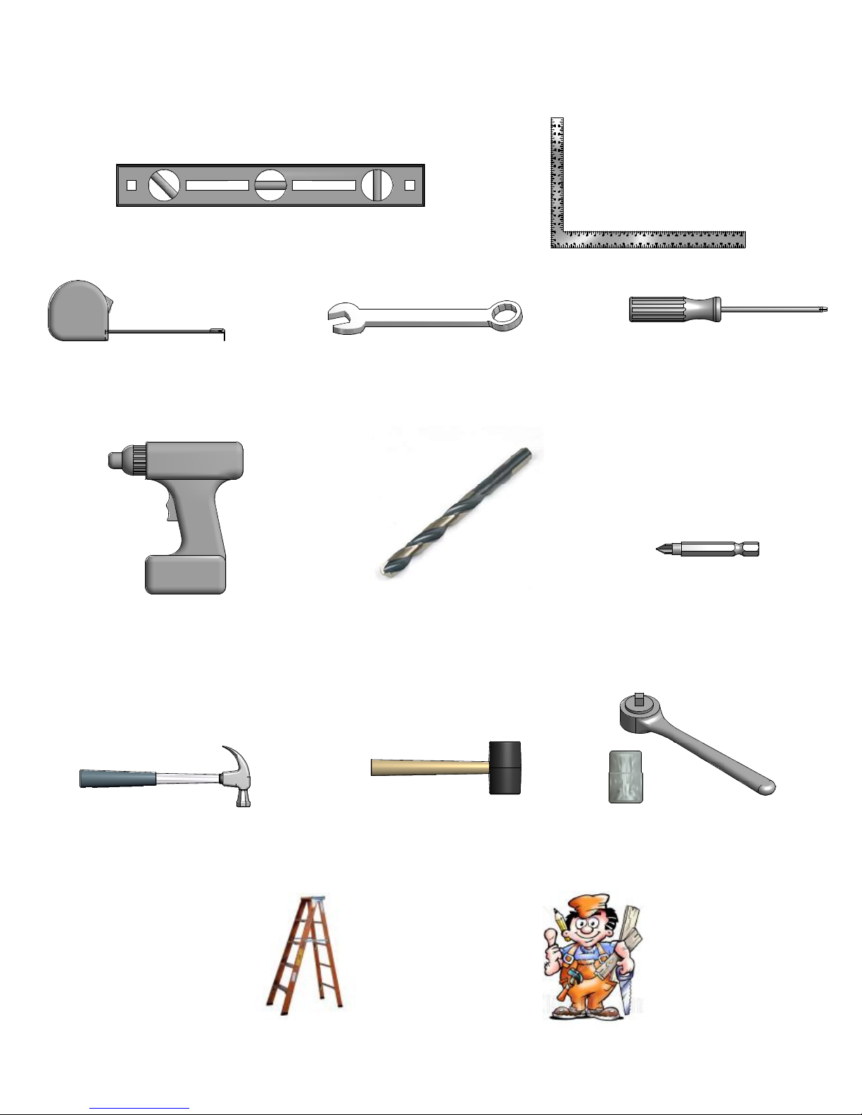
Tools Required for Installation:
(These are the tools that are generally required for assembly of our outdoor products. These tools
are not included with the outdoor product purchase.)
(Square)
(Level 24")
(Tape Measure)
(Cordless Drill or Electric Drill)
(Open End Wrenches 1/2")
(1/8" & 7/16" Drill Bits)
(Phillips Screw Driver)
(Drill Attachments:
Phillips Head)
(Claw Hammer)
(Ladder)
(Rubber Mallet - Optional)
(An Adult w/ an Adult Helper)
(3/8" Drive Ratchet, 1/2" STD
Sockets 1/2" Deep Sockets)
Page 13
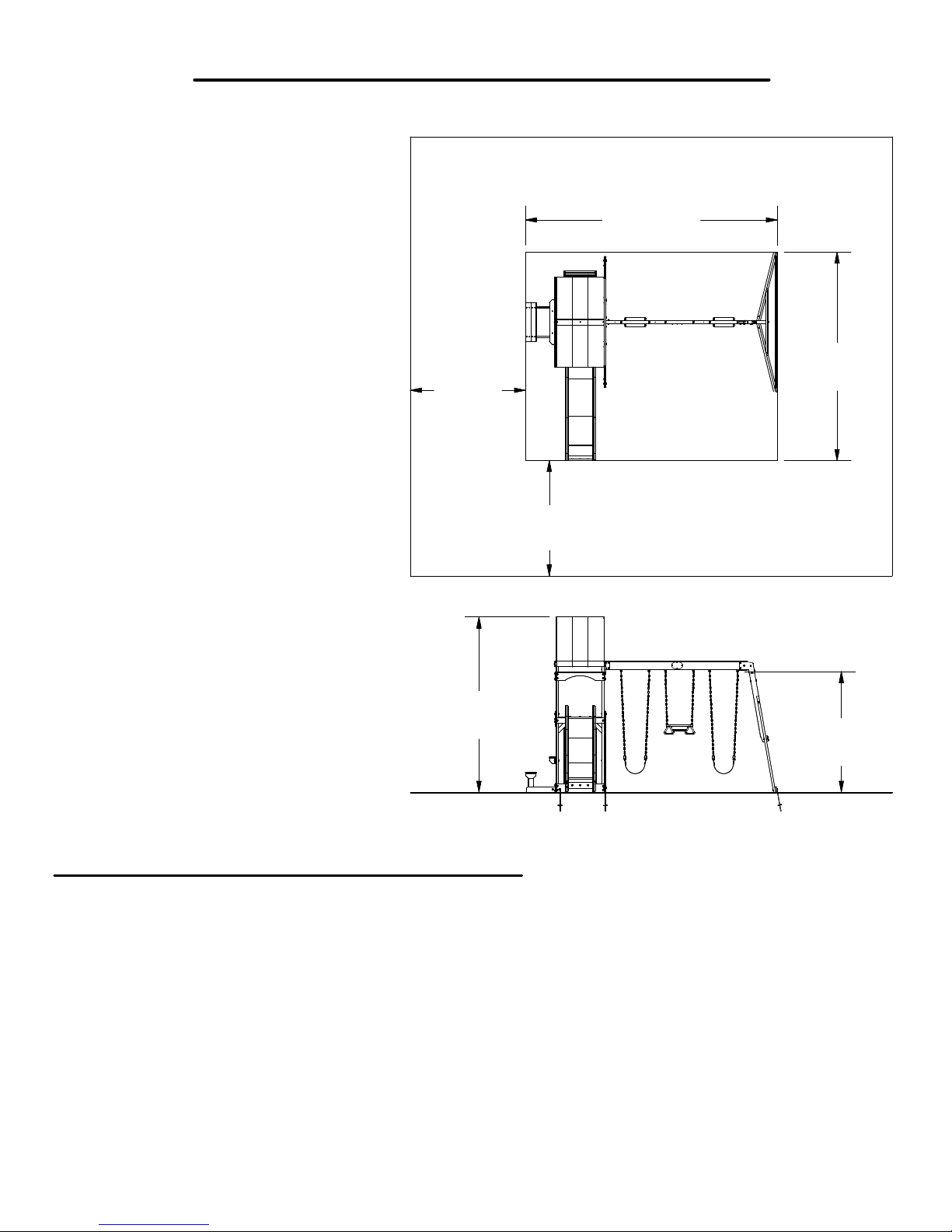
Basic Setup Dimensions
Place the set on level ground, not less than 6 ft [2 m] from any structure or obstruction such
as a fence, garage, house, overhanging branches, laundry lines, or electrical wires.
13'-1 9/16"
[4 m]
10'-10 3/16"
6'-0"
[1.8 m]
[3.3 m]
6'-0"
[1.8 m]
General Information:
Your set has been designed and engineered for
children only and for residential use only.
A maximum of 150 lbs. per child is recommended
for play activities designed for individual use.
A maximum of 120 lbs. per child is recommended
for play activities designed for multiple child use.
A maximum of 9 children is recommended for this
swing set.
Important Assembly Notes
1) While assembling unit, take time before and after each phase to make sure fort is level. If fort is
not level, assembly will be difficult and improper assembly may result. Extra care must be taken to
insure the fort is square.
2) Tighten bolts securely, tighten nuts on bolts flush to the tube or member, and place caps over
exposed bolts snug to the nut.
3) Pay close attention to the ITEMS NEEDED FOR EACH PHASE. They can be a valuable aid when
sorting your wood and hardware. Assembly will be made easier if items are sorted by phase.
4) Pay close attention to make sure you are using the correct hardware in the correct phases. Using
incorrect hardware may result in improper assembly.
5) Whenever a T-nut is used, follow these directions. Place T-nut in pre-drilled hole. Tap in with hammer.
Place bolt with washers in the opposite side. Hand tighten to make sure the bolt is in the T-nut.
DO NOT over tighten.
6) Read the steps of each phase thoroughly. The written steps may include important information not
shown in the illustrations.
9'-1 5/16"
[2.8 m]
Safe play height: 15'-1 5/16" [4.5 m]
Maximum fall height: 6'-3 1/4" [1.9 m]
Safe Play Zone
6'-3 1/4"
[1.9 m]
Page 14
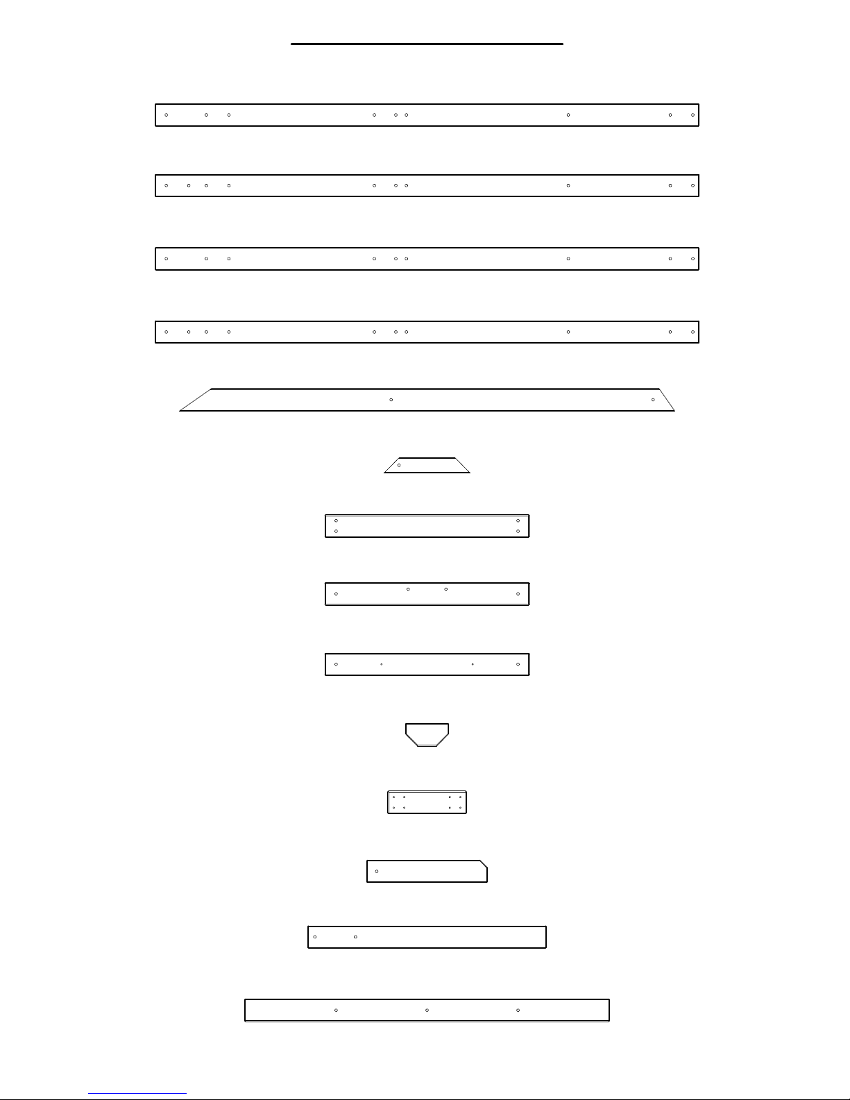
Parts Identification
Wood Components
(NOT TO SCALE)
E1 - UPRIGHT - W103800
(1)
1 3/8"x3 3/8"x81 3/4" (36x86x2076)
E2 - UPRIGHT - W103807
(1)
1 3/8"x3 3/8"x81 3/4" (36x86x2076)
E3 - UPRIGHT - W103809
(1)
1 3/8"x3 3/8"x81 3/4" (36x86x2076)
E4 - UPRIGHT - W103808
(1)
1 3/8"x3 3/8"x81 3/4" (36x86x2076)
E77 - ANGLE BRACE - W100991
(2)
1 3/8"x3 3/8"x74 3/8" (36x86x1890)
F71 - STANDARD ANGLE BRACE - W100689
(4)
1 3/8"x2 3/8"x13" (36x60x330)
H1 - FLOOR RAIL - W103804
(2)
1"x3 3/8"x30 3/4" (24x86x780)
H2 - SWING BEAM MOUNT - W103814
(1)
1"x3 3/8"x30 3/4" (24x86x780)
H3 - WALL RAIL - W103815
(1)
1"x3 3/8"x30 3/4" (24x86x780)
H4 - BENCH SEAT SUPPORT - W104040
(2)
1"x3 3/8"x6 1/2" (24x86x166)
H5 - BENCH UPRIGHT - W104041
(2)
1"x3 3/8"x11 3/4" (24x86x300)
(2)
(2)
(1)
H6 - BENCH GROUND BOARD - W104042
1"x3 3/8"x18 1/8" (24x86x460)
H7 - VERTICAL TARP SUPPORT - W103819
1"x3 3/8"x35 7/8" (24x86x910)
H8 - HORIZONTAL TARP SUPPORT - W103816
1"x3 3/8"x54 3/4" (24x86x1392)
Page 15
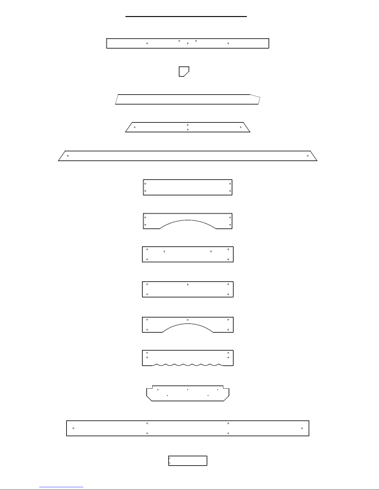
Parts Identification
Wood Components
(NOT TO SCALE)
H9 - HORIZONTAL TARP SUPPORT - W103818
(1)
1"x3 3/8"x54 3/4" (24x86x1392)
H10 - SHELF SUPPORT - W103961
(2)
1"x3 3/8"x3 3/8" (24x86x86)
H73 - ROCK WALL RAIL - W100024
(2)
24"x86"x1238" (24x86x1238)
H79 - END SUPPORT - W100992
(1)
1"x3 1/2"x42" (24x86x1072)
H80 - GROUND BOARD - W100990
(1)
1"x3 3/8"x87 3/8" (24x86x2218)
K1 - GROUND BOARD - W103803
(2)
5/8"x5 1/4"x30" (16x134x762)
K2 - ARCH BOARD - W103812
(2)
5/8"x5 1/4"x30" (16x134x762)
K3 - GROUND BOARD - W103801
(1)
5/8"x5 1/4"x30 3/4" (16x134x780)
K4 - WALL RAIL - W103810
(1)
5/8"x5 1/4"x30 3/4" (16x134x780)
K5 - WINDOW ARCH BOARD - W103811
(1)
5/8"x5 1/4"x30 3/4" (16x134x780)
K6 - DECORATIVE WALL BOARD - W103829
(1)
5/8"x5 1/4"x30 3/4" (16x134x780)
K7 - LEMONADE SHELF - W103825
(1)
5/8"x5 1/4"x27 7/8" (16x134x708)
K8 - GROUND BOARD - W103802
(1)
5/8"x5 1/4"x81 3/4" (16x134x2076)
M1 - WALL BOARD - W103827
(5)
5/8"x3 3/8"x13" (16x86x330)
Page 16
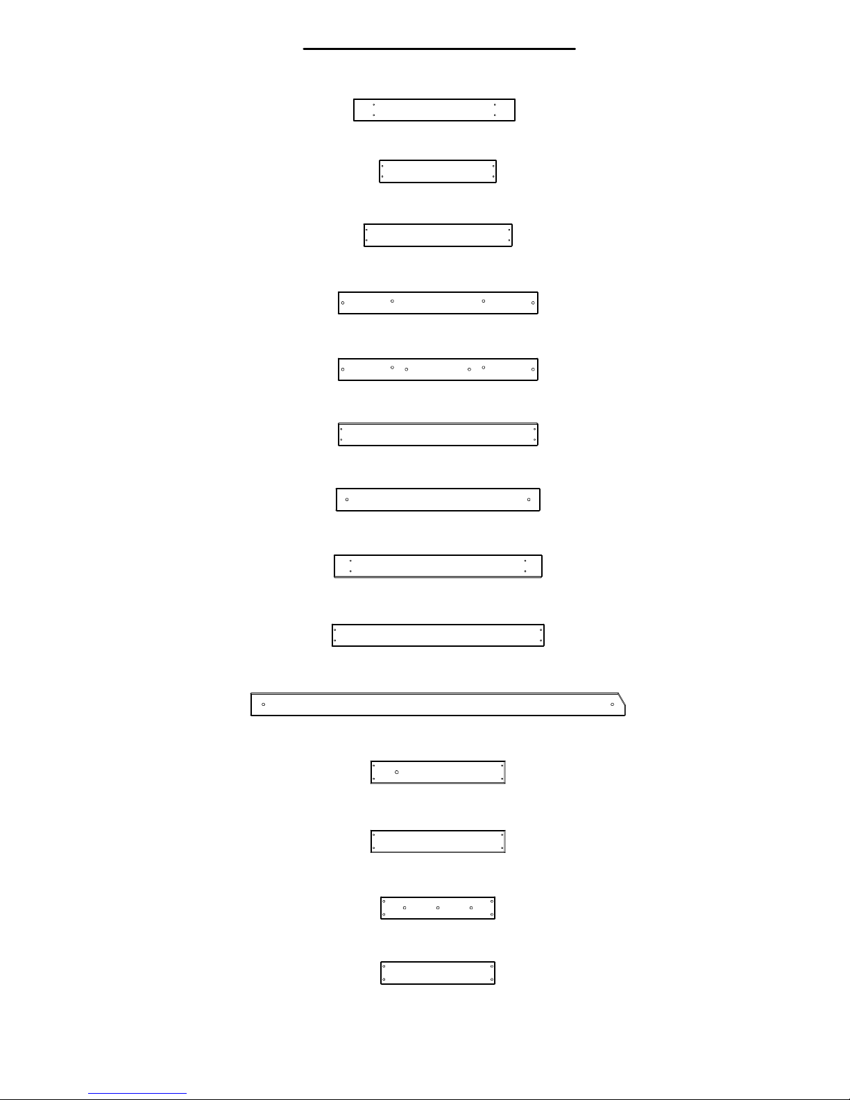
Parts Identification
Wood Components
(NOT TO SCALE)
M2 - BENCH SEAT - W104043
(2)
5/8"x3 3/8"x24 3/8" (16x86x618)
M3 - FLOOR BOARD - W103824
(7)
5/8"x3 3/8"x17 5/8" (16x86x448)
M4 - FLOOR BOARD - W103823
(9)
5/8"x3 3/8"x22 3/8" (16x86x568)
M5 - FLOOR RAIL - W103805
(1)
5/8"x3 3/8"x30" (16x86x762)
M6 - FLOOR RAIL - W103806
(1)
5/8"x3 3/8"x30" (16x86x762)
M7 - TOP TARP SUPPORT - W103820
(1)
5/8"x3 3/8"x30" (16x86x762)
M8 - WALL RAIL - W103813
(3)
5/8"x3 3/8"x30 3/4" (16x86x780)
M9 - FLOOR BOARD - W103822
(1)
5/8"x3 3/8"x31 1/4" (16x86x794)
M10 - END TARP SUPPORT - W103817
(2)
5/8"x3 3/8"x31 7/8" (16x86x810)
M11 - ANGLE BRACE - W103826
(2)
5/8"x3 3/8"x56 3/8" (16x86x1431)
M71 - ROCK BOARD - W100022
(6)
5/8"x3 3/8"x20 1/4" (16x86x514)
M72 - ROCK WALL SLAT - W100023
(2)
5/8"x3 3/8"x20 1/4" (16x86x514)
M77 - SLIDE BRACE - W100544
(1)
5/8"x3 3/8"x17 1/4" (16x86x438)
M78 - CENTER SLIDE BRACE - W100545
(2)
5/8"x3 3/8"x17 1/4" (16x86x438)
Page 17
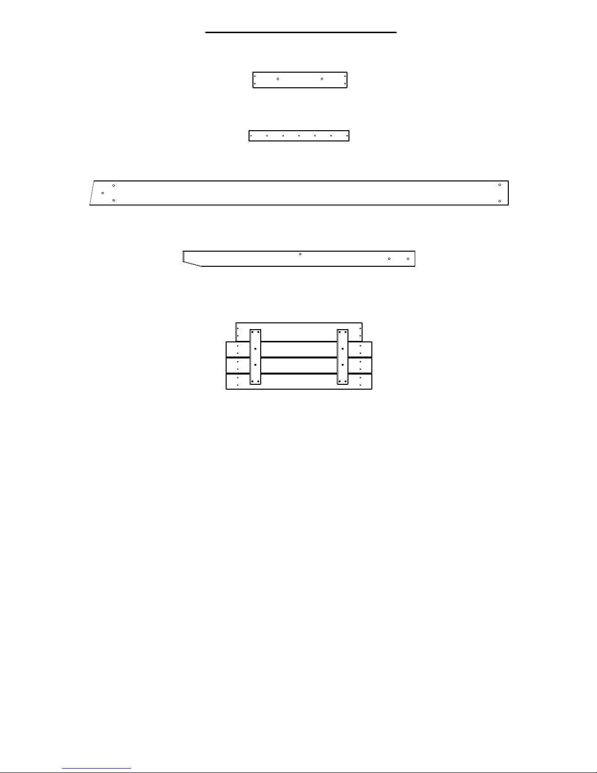
Parts Identification
Wood Components
(NOT TO SCALE)
M102 - ATTACHMENT BOARD - W103690
(1)
5/8"x3 3/8"x20 1/4" (16x86x514)
N1 - WINDOW BOARD - W103828
(1)
5/8"x2 3/8"x21 1/2" (16x60x546)
SB74 - SWING BEAM EXTENDED - W102419
(1)
2"x5 1/4"x89 1/2" (50x134x2274)
W71 - SWING BEAM SUPPORT - W102420
(1)
2"x3 3/8"x49 5/8" (50x86x1260)
(2)
FP1 - FLOOR PANEL - W103821
Page 18
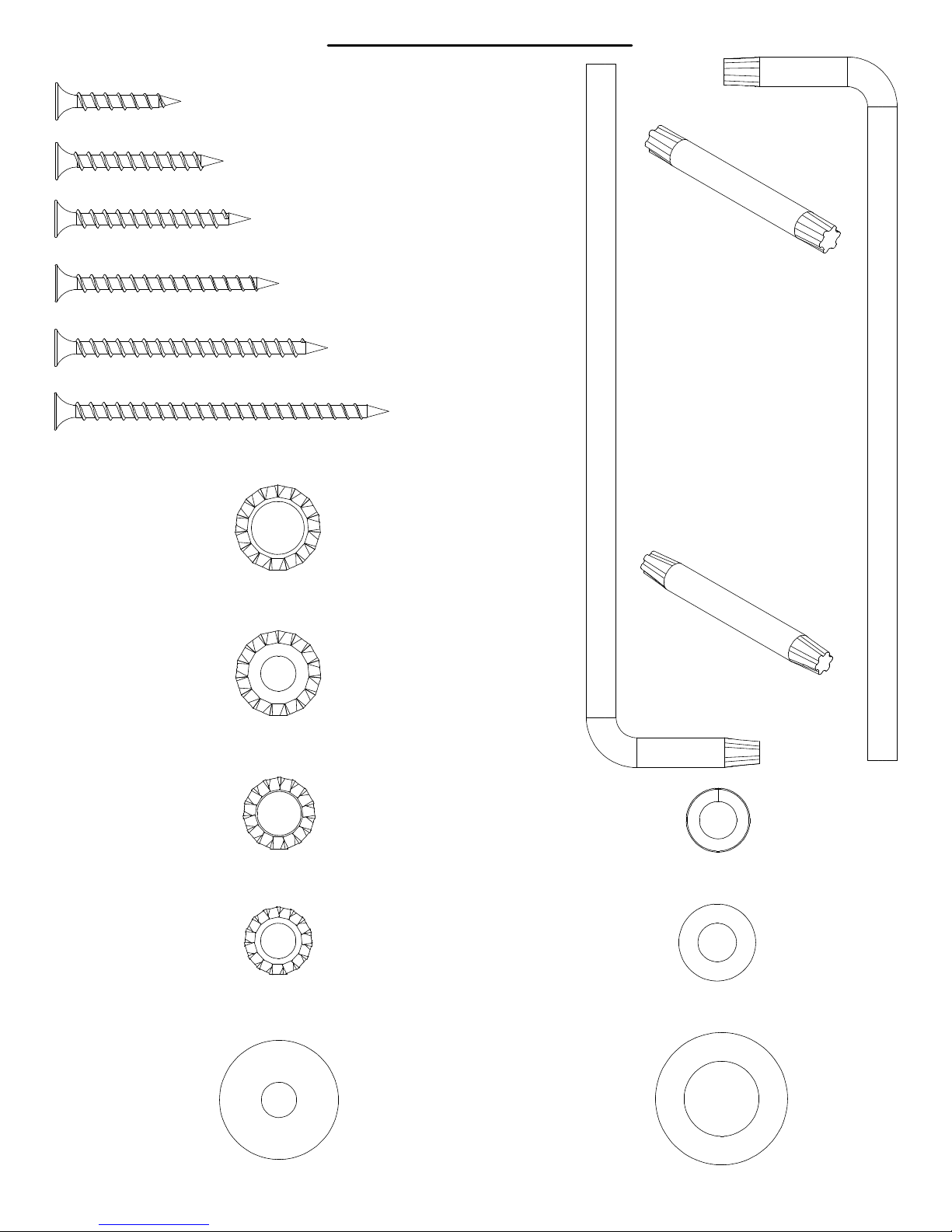
(95)
BR - SCREW PFH 8x1-1/8 - H100088
(84)
BP - SCREW PFH 8x1-1/2 - H100086
(26)
BS - SCREW PFH 8x1-3/4 - H100089
(13)
CK - SCREW PFH 8x2 - H100111
(2)
BT - SCREW PFH 8x2-1/2 - H100090
(26)
BW - SCREW PFH 8x3 - H100092
(70)
AD - WASHER LOCK EXT 12x19 - H100031
Parts Identification
Hardware
4
1
1
0
0
1
H
h
c
n
e
r
W
x
r
o
T
0
3
T
-
)
2
(
(2)
- T-40 Torx Bit - A100042
)
2
(
1
4
0
0
0
1
A
h
c
n
e
r
W
x
r
o
T
0
4
T
-
(91)
AC - WASHER LOCK EXT 8x19 - H100030
(7)
KW - WASHER LOCK EXT 8x15 - H100139
(4)
KV - WASHER LOCK EXT 6x15 - H100138
(2)
- T-30 Torx Bit - H100147
(4)
BX - WASHER SPLIT 5/16 - H100095
(7)
CE - WASHER FLAT 9x18 - H100106
(15)
CD - WASHER FLAT 8x27 - H100105
(6)
CB - WASHER SAFETY 17x30 - H100103
Page 19
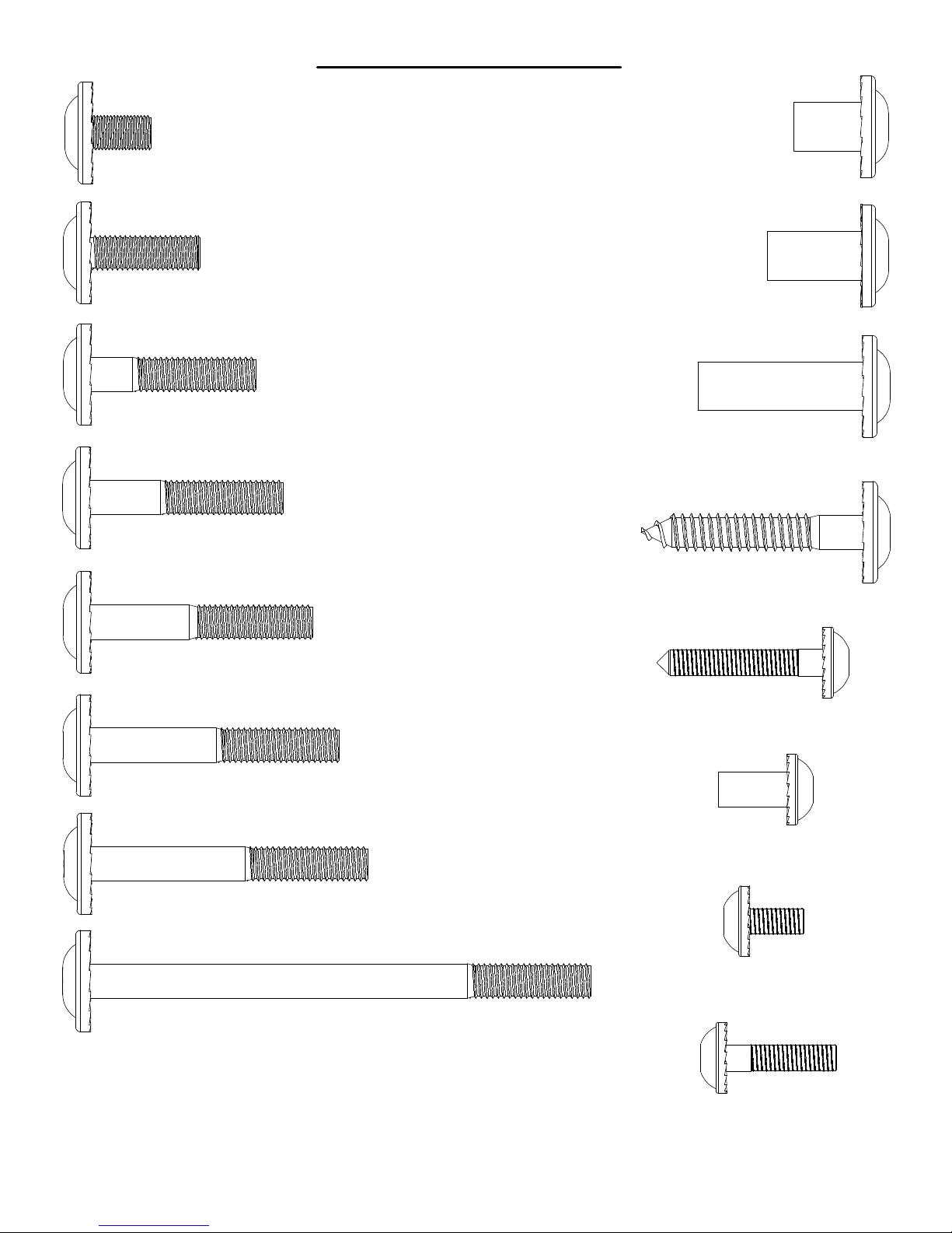
(11)
CM - BOLT WH 5/16x1/2 - H100115
(7)
F - BOLT WH 5/16x1 - H100008
(25)
H - BOLT WH 5/16x1-1/2 - H100010
Parts Identification
Hardware
(13)
B - NUT BARREL WH 5/16x5/8 - H100004
(60)
D - NUT BARREL WH 5/16x7/8 - H100005
(2)
C - NUT BARREL WH 5/16x1-1/2 - H100006
(6)
J - BOLT WH 5/16x1-3/4 - H100011
(21)
K - BOLT WH 5/16x2 - H100012
(2)
L - BOLT WH 5/16x2-1/4 - H100013
(7)
M - BOLT WH 5/16x2-1/2 - H100014
(28)
Z - LAG SCREW WH 5/16x2 - H100027
(4)
LC - LAG SCREW WH 1/4x1-1/2 - H100145
(7)
KS - NUT BARREL WH 1/4x5/8 - H100136
(4)
KY - BOLT WH 1/4x1/2" - H100141
(1)
KA - BOLT WH 5/16x4-1/2 - H100021
(2)
KT - BOLT WH 1/4x1 - H100137
Page 20
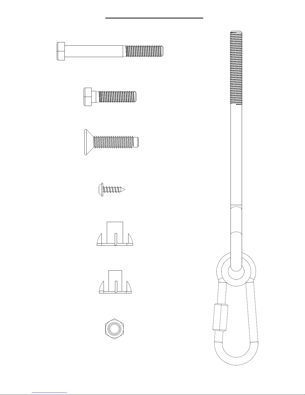
Parts Identification
(2)
AN - BOLT HEX 5/16x2-3/4 - H100047
(4)
AJ - BOLT HEX 5/16x1-1/4 - H100042
(7)
A - BOLT FA 3/8x1-1/2 - H100001
(14)
CY - SCREW PWH 8x5/8 - H100128
Hardware
)
6
(
9
9
0
0
0
1
H
K
N
I
L
K
C
I
U
Q
R
E
G
N
A
H
G
N
I
W
S
Z
B
(7)
BF - T-NUT 3/8 - H100073
(8)
BG - T-NUT 5/16 - H100074
(9)
CJ - NUT LOCK 5/16 - H100110
Page 21
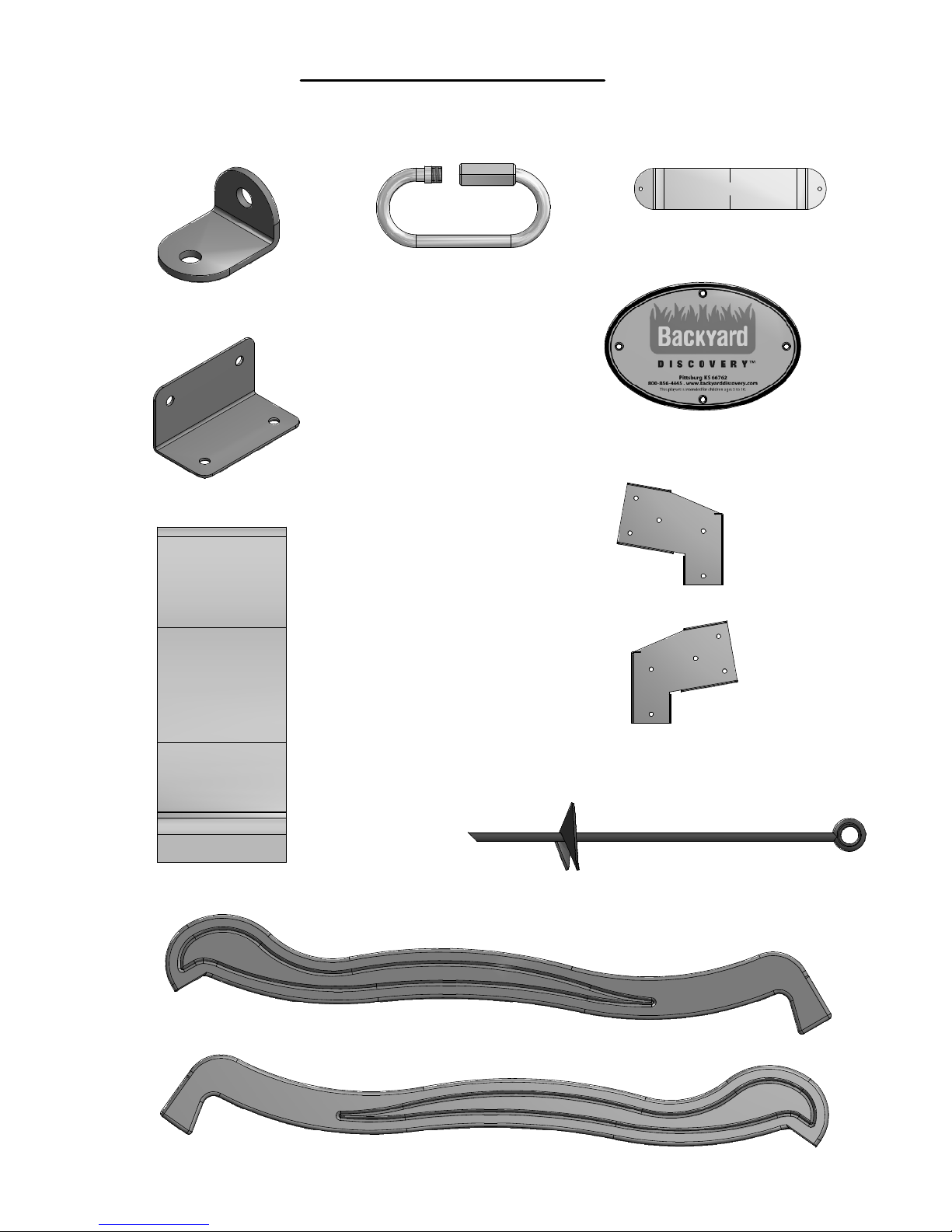
Parts Identification
(2)
ES - L BRACKET GREEN 32x51 - A100061
(2)
GD - L BRACKET 66x66x127 - A100140
Accessories
(NOT TO SCALE)
(4)
FA - QUICK LINK - A100069
(2)
FB - SWING SEAT YELLOW - A100070
HC - BYD ID TAG (LARGE) 2011 WITH AGES - A100164(1)
(1)
EM - SLIDE BED 8' YELLOW - A100056
(1)
TC - SWING BEAM EXTENSION BRACKET-RIGHT - A100326
(1)
TB - SWING BEAM EXTENSION BRACKET-LEFT - A100325
(6)
KC - METAL GROUND STAKE BROWN - A100178
(1)
EK - SLIDE RAIL 8' GREEN RIGHT - A100054
(1)
EL - SLIDE RAIL 8' GREEN LEFT - A100055
Page 22
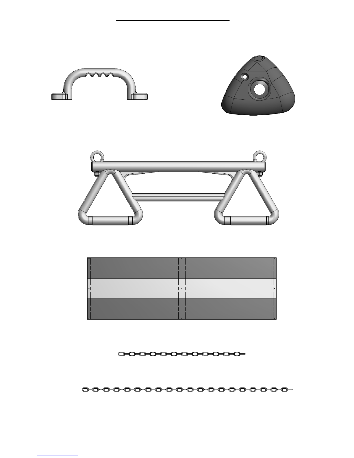
Parts Identification
(2)
EA - HAND GRIP YELLOW PLASTIC - A100043
Accessories
(NOT TO SCALE)
(6)
ER - CLIMBING ROCK GREEN SMALL - A100060
(1)
TN - TRAPEZE WITH HARDWARE YELLOW - A100334
(1)
WT - TARP .4x752x2309 - A100398
(2)
KN - CHAIN GREEN 31" - A100177
(4)
EZ - CHAIN GREEN 51.25" - A100068
Page 23
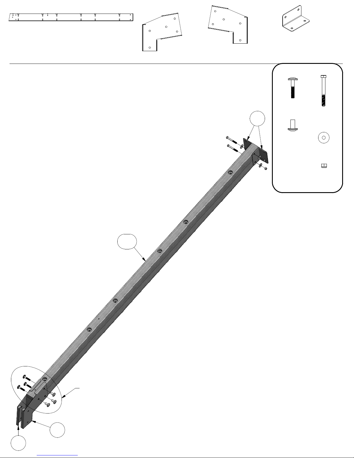
SB74 - SWING BEAM EXTENDED - W102419
(1)
2"x5 1/4"x89 1/2" (50x134x2274)
(1)
TB - SWING BEAM EXTENSION BRACKET-LEFT - A100325
4 FT GREEN EXTENDED
SWING BEAM WITH
TRAPEZE
STEP 1
ATTACH (2) GD BRACKETS TO SB74 SWING
BEAM USING 2-3/4" BOLT, FLAT WASHERS AND
5/16" LOCK NUT, AS SHOWN.
ATTACH TB AND TC SWING BEAM EXTENSION
BRACKETS TO SB74 SWING BEAM USING 13/4" BOLTS AND 7/8" BARREL NUTS, AS
SHOWN.
(2)
GD - L BRACKET 66x66x127 - A100140
(1)
TC - SWING BEAM EXTENSION BRACKET-RIGHT - A100326
(3)
GD
NUT BARREL
(3)
WH 5/16x7/8
BOLT WH
5/16x1-3/4
BOLT HEX
(2)
5/16x2-3/4
WASHER
(4)
FLAT 8x27
NUT LOCK
(2)
5/16
SB74
FINGER TIGHTEN ONLY AT THIS TIME.
TC
TB
Page 24
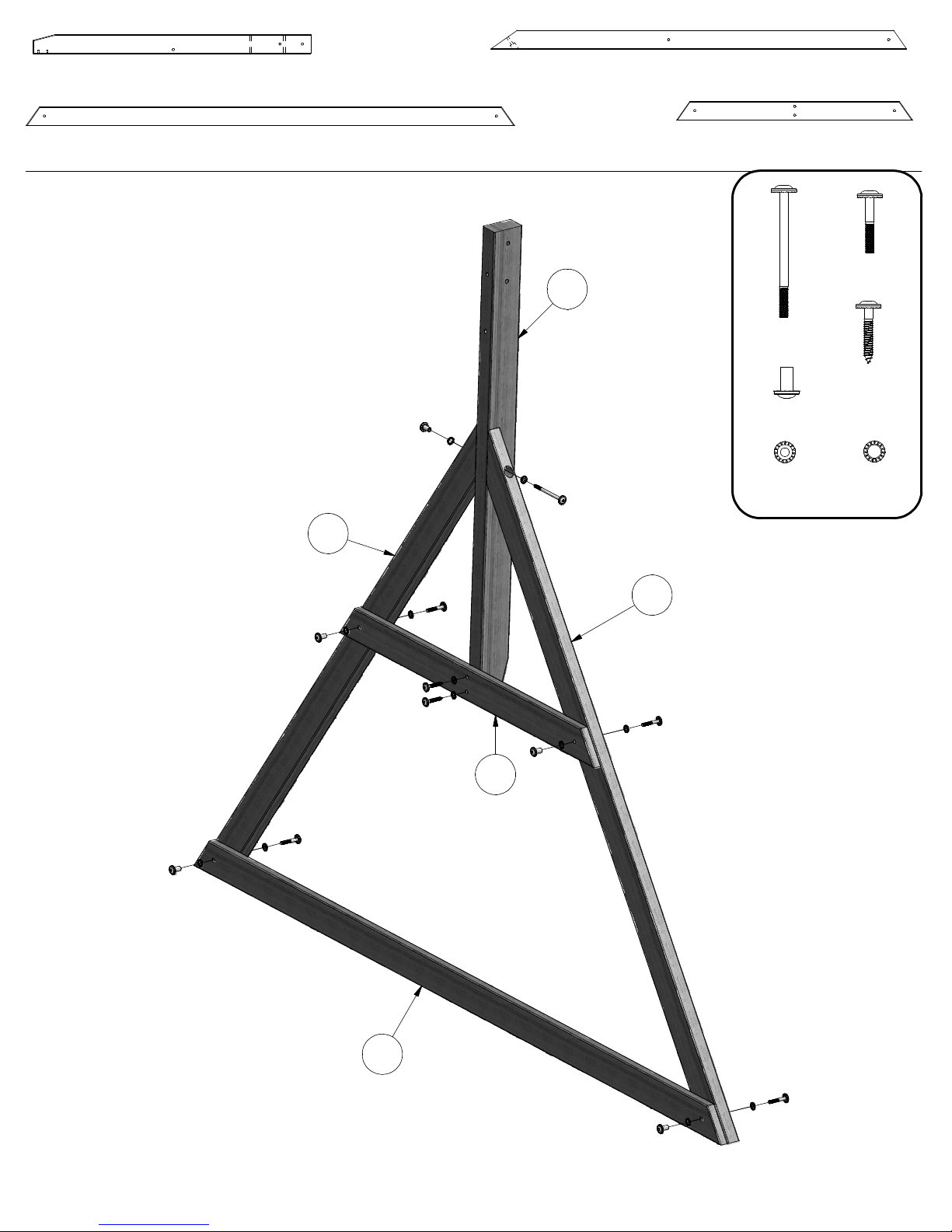
W71 - SWING BEAM SUPPORT - W102420
(1)
2"x3 3/8"x49 5/8" (50x86x1260)
E77 - ANGLE BRACE - W100991
(2)
1 3/8"x3 3/8"x74 3/8" (36x86x1890)
H80 - GROUND BOARD - W100990
(1)
1"x3 3/8"x87 3/8" (24x86x2218)
STEP 2
ATTACH H80 GROUND BOARD TO (2) E77
ANGLED SUPPORT BOARDS USING 2" BOLTS,
LOCK WASHERS AND 7/8" BARREL NUTS, AS
SHOWN.
ATTACH (2) E77 ANGLED SUPPORT BOARDS
TO W71 SUPPORT USING 4- 1/2" BOLTS, LOCK
WASHERS AND 7/8" BARREL NUTS, AS
SHOWN.
ATTACH H79 BOARD TO W71 BOARD USING 2"
LAG SCREWS AND LOCK WASHERS. NEXT,
SECURE THE ENDS OF H79 BOARD TO E77
ANGLED SUPPORTS USING 2" BOLTS, LOCK
WASHERS AND 7/8" BARREL NUTS, AS
SHOWN.
E77
W71
H79 - END SUPPORT - W100992
(1)
1"x3 1/2"x42" (24x86x1072)
(4)
BOLT WH
(1)
5/16x4-1/2
(2)
NUT BARREL
(5)
WH 5/16x7/8
WASHER
(7)
LOCK EXT
8x19
BOLT WH
5/16x2
LAG SCREW
WH 5/16x2
WASHER
(5)
LOCK EXT
12x19
H79
E77
H80
Page 25
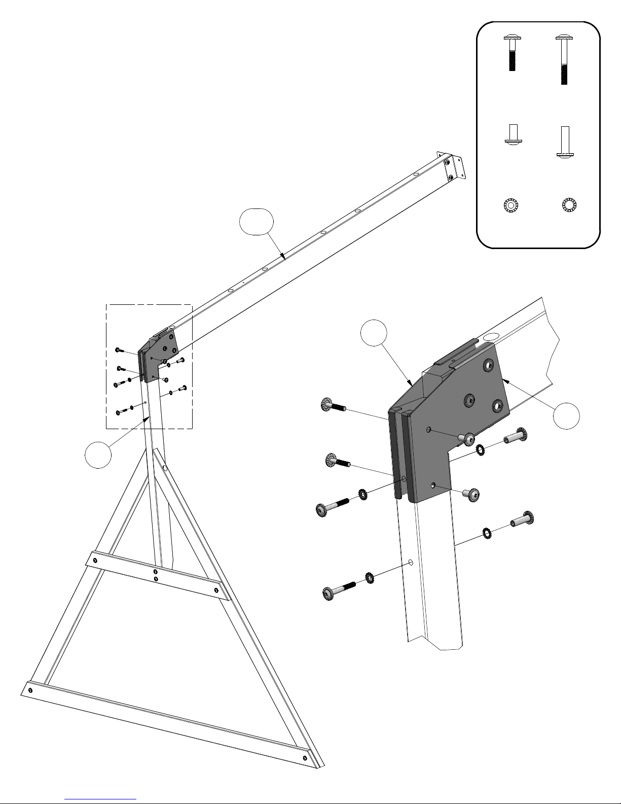
STEP 3
INSERT W71 BOARD INTO TB AND TC
BRACKET OPENING AND SECURE USING
1-3/4" BOLTS AND 7/8" BARREL NUTS, AS
SHOWN.
INSERT 2-1/2" BOLTS, LOCK WASHERS AND
1-1/2" BARREL NUTS INTO THE EDGE OF W71
BOARD, AS SHOWN.
BOLT WH
(2)
5/16x1-3/4
NUT BARREL
(2)
WH 5/16x7/8
BOLT WH
(2)
5/16x2-1/2
NUT BARREL
(2)
WH 5/16x1-1/2
W71
SB74
(2)
WASHER
LOCK EXT
8x19
(2)
WASHER
LOCK EXT
12x19
TB
TC
Page 26
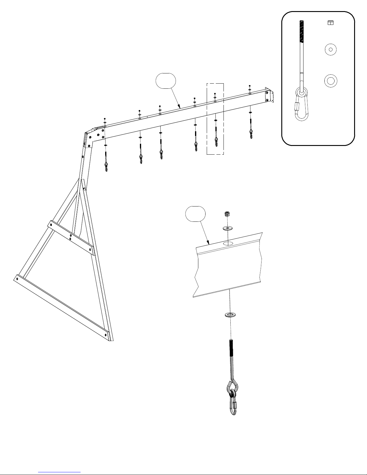
STEP 4
INSERT (6) SWING HANGER QUICK LINK INTO SB74 SWING BEAM USING SAFETY
WASHERS, FLAT WASHERS AND 5/16" LOCK NUTS, AS SHOWN.
NUT LOCK
(6)
WASHER
(6)
FLAT 8x27
5/16
SB74
SB74
WASHER
(6)
SAFETY
17x30
SWING
HANGER
(6)
QUICK LINK
Page 27
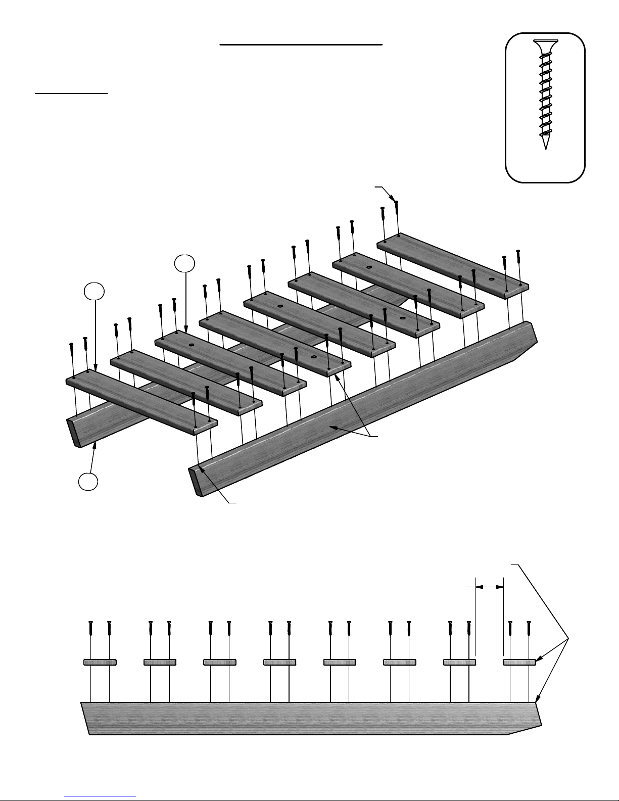
4' Rock Ladder
Phase 1
Phase Notes
• Assemble slats to rails as shown.
• Note oreintation of slats, be sure to arrange as shown.
• See drawing below for slat spacing on rails.
• Using slats as a guide, pre-drill top edges of rails
with a 1/8" drill bit. Failure to pre-drill may result in
board splitting.
M71
M72
SCREW PFH 8x1-1/2
(32 PLCS)
TOP
(32)
SCREW PFH
8x1-1/2
H73
THESE SURFACES FLUSH BOTH SIDES
PRE-DRILL TOP EDGE OF RAILS
ALIGN FRONT EDGE OF SLAT WITH TOP OF RAIL
2 15/16
TYPICAL SLAT SPACING
7 SPACES
TOP
Page 28
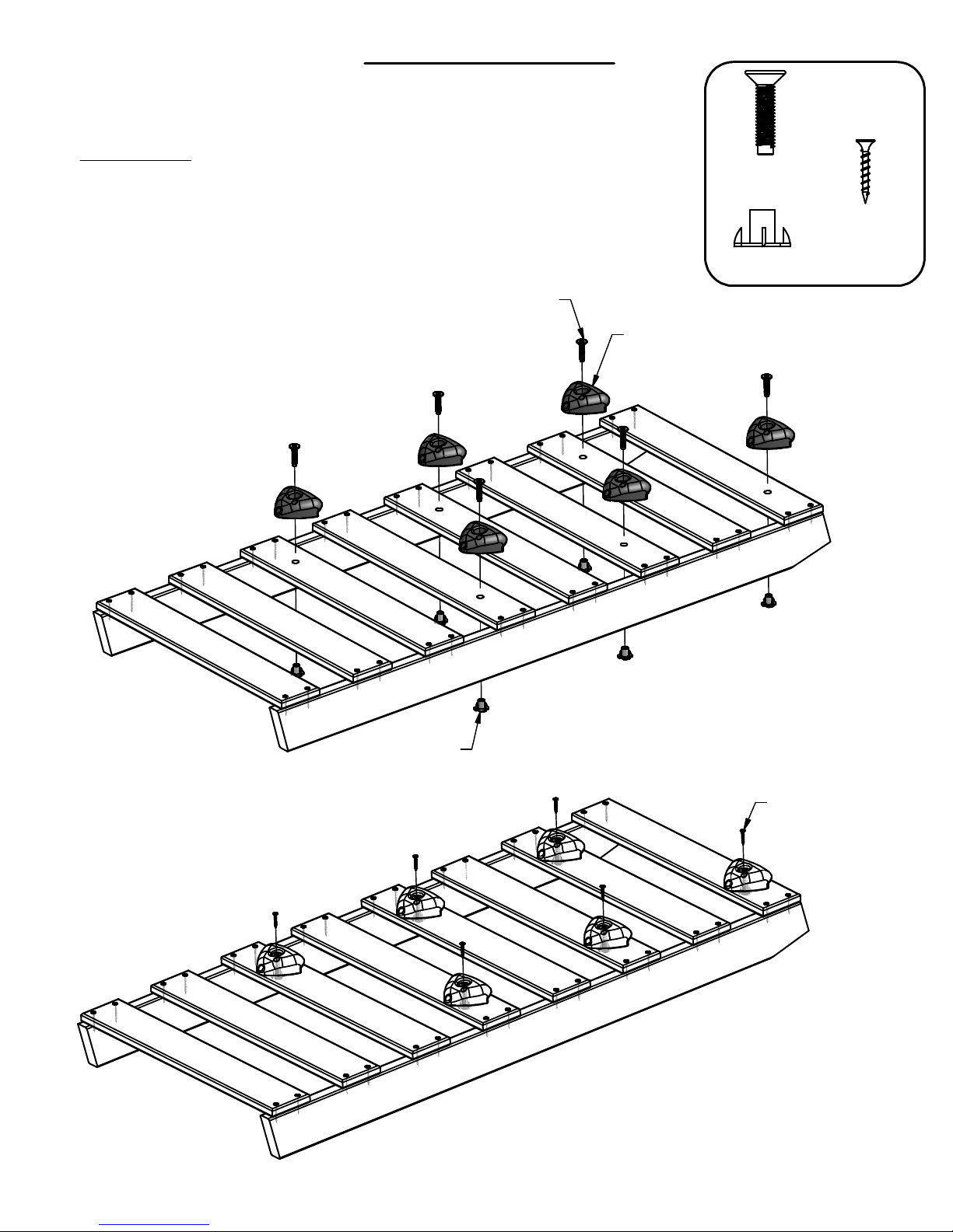
4' Rock Ladder
Phase 2 & 3
Phase Notes
• Oreint top edge of rocks with top edge of slats.
• Fasten rocks as shown.
BOLT FA 3/8x1-1/2
(6 PLCS)
BOLT FA
(6)
3/8x1-1/2
T-NUT 3/8
(6)
CLIMBING ROCK GREEN SMALL
(6 PLCS)
(6)
SCREW PFH
8x1-1/8
T-NUT 3/8
(6 PLCS)
SCREW PFH 8x1-1/8
(6 PLCS)
Page 29
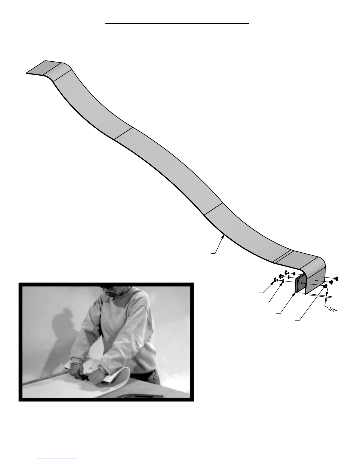
TOP
8 FOOT SLIDE ASSEMBLY
PHASE 1
STEP 1
● PLACE SLIDE BRACE CENTERED ON THE BOTTOM 1/4" FROM THE EDGE. TRANSFER HOLES
ON THE BOARD THROUGH THE SLIDE BED AS SHOWN BELOW. USE A 3/8" DRILL BIT.
● ATTACH SLIDE BRACE TO SLIDE USING HARDWARE SHOWN.
QTY DESCRIPTION
1 SLIDE BRACE
3 BOLT WH 5/16x1/2
3 NUT BARREL WH 5/16x5/8
3 WASHER LOCK EXT 12x19
1 SLIDE BED 8' YELLOW
(SEE SLIDE ASSEMBLY
INSTALLATION STEP FOR
TOP MOUNTING HOLE
DRILLING LOCATIONS).
SLIDE BED 8' YELLOW
NUT BARREL WH 5/16x5/8
WASHER LOCK EXT 12x19
BOTTOM
M77 SLIDE BRACE
BOLT WH 5/16x1/2
USE M77 SLIDE BRACE AS A TEMPLATE
FOR DRILLING BOTTOM HOLE PATTERN
IN SLIDE BED. BE SURE TO PLACE
SLIDE BRACE UP 1/4" FROM BOTTOM
EDGE OF SLIDE BED BEFORE MARKING
HOLE PATTERN.
TIP: PREBENDING THE ENDS WILL EASE ASSEMBLY.
REV 8/02/11 BRS
Page 30
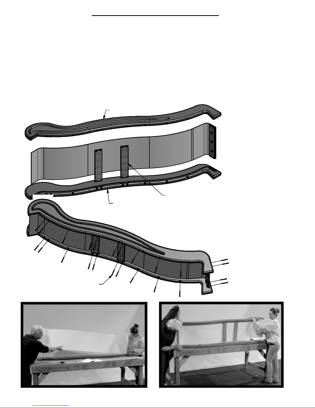
2 M78
CENTER SLIDE BRACE
1 SLIDE RAIL 8' GREEN RIGHT
8 FOOT SLIDE ASSEMBLY
PHASE 2
STEP 2
● PLACE 1 SLIDE RAIL ON A FLAT SURFACE AND BEGIN INSERTING SLIDE BED AT THE BOTTOM OF THE
SLIDE RAIL (FIG. 1). PUT SLIDE SUPPORT BOTTOM INTO THE SUPPORT POCKET AT THE BOTTOM OF THE
RAIL AND HAVE A HELPER BEND THE SLIDE BED TOWARDS THE TOP OF THE SLIDE AND INSERT
THE BED INTO THE SLIDE CAVITY. MAKE SURE SLIDE BED IS COMPLETELY DOWN IN THE SLIDE
CAVITY. SECURE USING (12) 3" WOOD SCREWS AT EACH OF THE PILOT HOLE LOCATIONS AS SHOWN BELOW.
● PLACE THE OTHER SLIDE RAIL ON A FLAT SURFACE WITH THE SLIDE CAVITY UP. HAVE A HELPER
HOLD THE TOP END OF SLIDE BED AND BEGIN INSERTING THE SLIDE BED AND SLIDE BRACES INTO
THE CAVITY AND SUPPORT POCKETS STARTING AT THE BOTTOM OF SLIDE AND WORKING UP TO
THE TOP(FIG. 2). SECURE USING (12) 3" WOOD SCREWS AT EACH OF THE PILOT HOLE LOCATIONS AS SHOWN BELOW.
SLIDE RAIL 8' GREEN RIGHT
SLIDE RAIL 8' GREEN LEFT
NOTE:
MAKE CERTAIN
SUPPORTS AND SLIDE
BED ARE FULLY
ENGAGED WITHIN
CHANNEL OF SLIDE
RAILS.
M78 CENTER SLIDE BRACE
QTY DESCRIPTION
24 SCREW PFH 8x3
1 SLIDE RAIL 8' GREEN LEFT
SCREW PFH 8x3
FIG. 1 FIG. 2
TIP: A HELPER IS REQUIRED FOR THIS PHASE.
Page 31
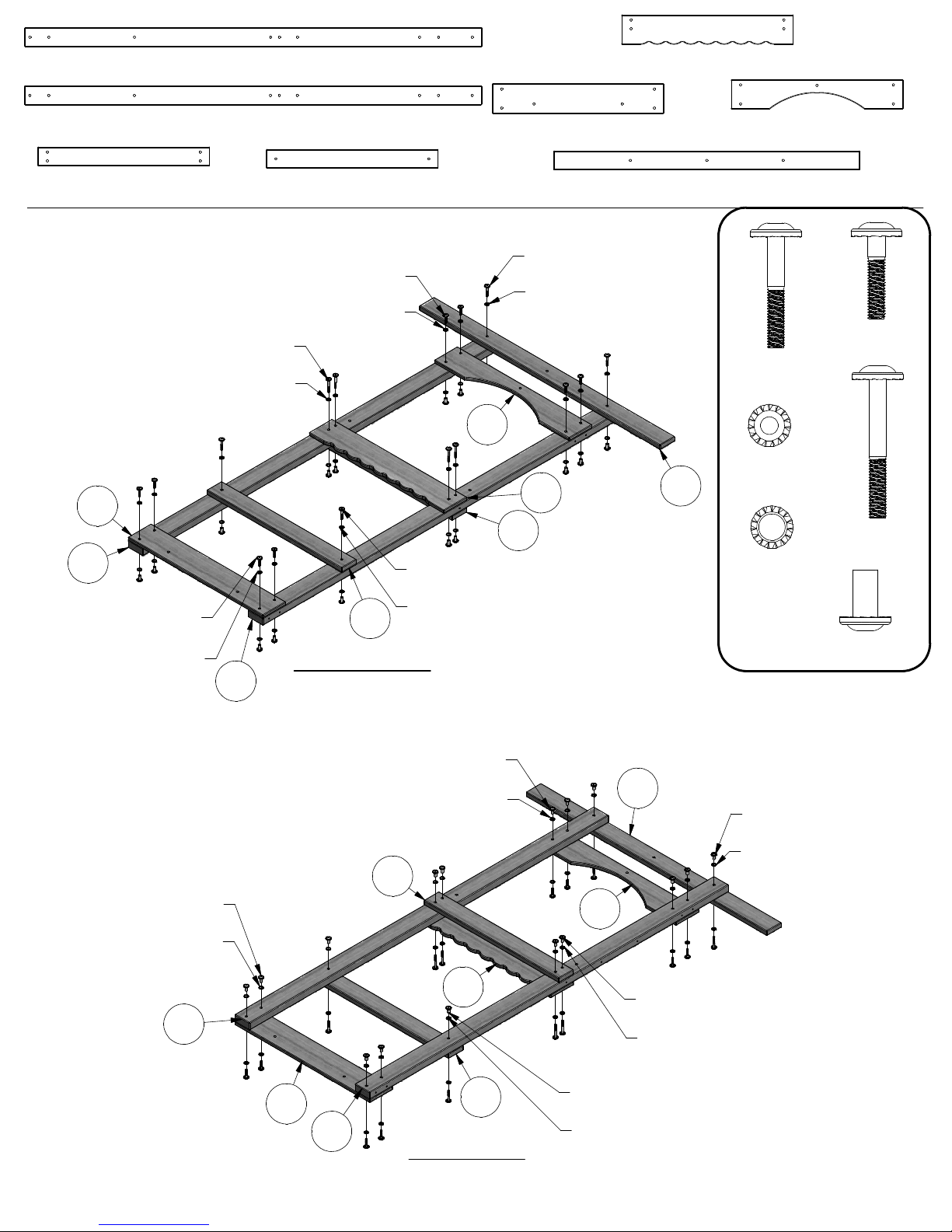
E1 - UPRIGHT - W103800
(1)
1 3/8"x3 3/8"x81 3/4" (36x86x2076)
K6 - DECORATIVE WALL BOARD - W103829
(1)
5/8"x5 1/4"x30 3/4" (16x134x780)
E3 - UPRIGHT - W103809
(1)
1 3/8"x3 3/8"x81 3/4" (36x86x2076)
H1 - FLOOR RAIL - W103804
(1)
1"x3 3/8"x30 3/4" (24x86x780)
STEP 1
BOLT WH 5/16x2-1/2
WASHER LOCK EXT 8x19
K3
E3
BOLT WH 5/16x1-1/2
(4 PLCS)
WASHER LOCK EXT 8x19
(4 PLCS)
H3 - WALL RAIL - W103815
(1)
1"x3 3/8"x30 3/4" (24x86x780)
BOLT WH 5/16x1-1/2
(4 PLCS)
WASHER LOCK EXT 8x19
(4 PLCS)
(4 PLCS)
(4 PLCS)
H3
OUTSIDE VIEW
E1
K3 - GROUND BOARD - W103801
(1)
5/8"x5 1/4"x30 3/4" (16x134x780)
(1)
BOLT WH 5/16x2
(2 PLCS)
WASHER LOCK EXT 8x19
(2 PLCS)
K5
K6
H1
BOLT WH 5/16x2
(2 PLCS)
WASHER LOCK EXT 8x19
(2 PLCS)
K5 - WINDOW ARCH BOARD - W103811
(1)
5/8"x5 1/4"x30 3/4" (16x134x780)
H8 - HORIZONTAL TARP SUPPORT - W103816
1"x3 3/8"x54 3/4" (24x86x1392)
(8)
BOLT WH
(4)
(16)
H8
5/16x2
WASHER
LOCK EXT
8x19
(4)
WASHER
LOCK EXT
(16)
12x19
(16)
BOLT WH
5/16x1-1/2
BOLT WH
5/16x2-1/2
NUT BARREL
WH 5/16x7/8
NUT BARREL WH 5/16x7/8
(4 PLCS)
WASHER LOCK EXT 12x19
(4 PLCS)
E1
NUT BARREL WH 5/16x7/8
WASHER LOCK EXT 12x19
H1
K3
E3
(4 PLCS)
(4 PLCS)
K6
H3
INSIDE VIEW
H8
NUT BARREL WH 5/16x7/8
(2 PLCS)
WASHER LOCK EXT 12x19
(2 PLCS)
K5
NUT BARREL WH 5/16x7/8
(4 PLCS)
WASHER LOCK EXT 12x19
(4 PLCS)
NUT BARREL WH 5/16x7/8
(2 PLCS)
WASHER LOCK EXT 12x19
(2 PLCS)
Page 32
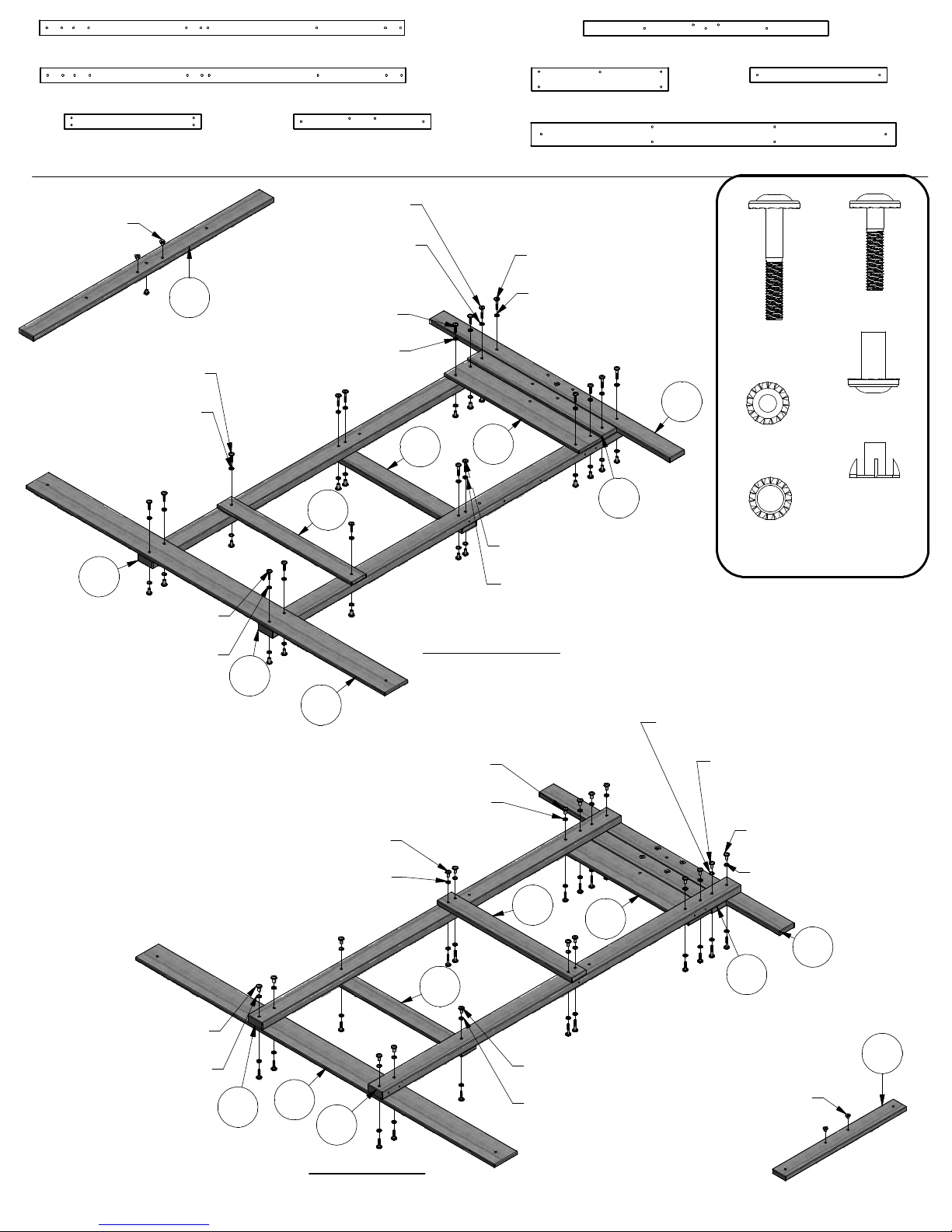
E2 - UPRIGHT - W103807
(1)
1 3/8"x3 3/8"x81 3/4" (36x86x2076)
H9 - HORIZONTAL TARP SUPPORT - W103818
(1)
1"x3 3/8"x54 3/4" (24x86x1392)
E4 - UPRIGHT - W103808
(1)
1 3/8"x3 3/8"x81 3/4" (36x86x2076)
H1 - FLOOR RAIL - W103804
(1)
1"x3 3/8"x30 3/4" (24x86x780)
STEP 2
T-NUT 5/16
(3 PLCS)
H9
BOLT WH 5/16x1-1/2
(2 PLCS)
WASHER LOCK EXT 8x19
(2 PLCS)
E2
BOLT WH 5/16x1-1/2
(4 PLCS)
WASHER LOCK EXT 8x19
(4 PLCS)
H2 - SWING BEAM MOUNT - W103814
(1)
1"x3 3/8"x30 3/4" (24x86x780)
BOLT WH 5/16x2
(2 PLCS)
WASHER LOCK EXT 8x19
(2 PLCS)
BOLT WH 5/16x1-1/2
(4 PLCS)
WASHER LOCK EXT 8x19
(4 PLCS)
M8
E4
(1)
H1
K4
BOLT WH 5/16x2
(4 PLCS)
WASHER LOCK EXT 8x19
(4 PLCS)
OUTSIDE VIEW
K4 - WALL RAIL - W103810
5/8"x5 1/4"x30 3/4" (16x134x780)
K8 - GROUND BOARD - W103802
(1)
5/8"x5 1/4"x81 3/4" (16x134x2076)
BOLT WH 5/16x2
(2 PLCS)
WASHER LOCK EXT 8x19
(2 PLCS)
H9
H2
M8 - WALL RAIL - W103813
(1)
5/8"x3 3/8"x30 3/4" (16x86x780)
(10)
BOLT WH
(8)
(18)
5/16x2
WASHER
LOCK EXT
8x19
NUT BARREL
(18)
WH 5/16x7/8
(5)
WASHER
LOCK EXT
(18)
12x19
BOLT WH
5/16x1-1/2
T-NUT 5/16
NUT BARREL WH 5/16x7/8
(4 PLCS)
WASHER LOCK EXT 12x19
(4 PLCS)
K8
NUT BARREL WH 5/16x7/8
WASHER LOCK EXT 12x19
NUT BARREL WH 5/16x7/8
(4 PLCS)
WASHER LOCK EXT 12x19
(4 PLCS)
E4
K8
E2
(4 PLCS)
(4 PLCS)
M8
WASHER LOCK EXT 12x19
(2 PLCS)
H1
K4
NUT BARREL WH 5/16x7/8
(2 PLCS)
WASHER LOCK EXT 12x19
(2 PLCS)
NUT BARREL WH 5/16x7/8
(2 PLCS)
NUT BARREL WH 5/16x7/8
(2 PLCS)
WASHER LOCK EXT 12x19
(2 PLCS)
H9
H2
H2
T-NUT 5/16
(2 PLCS)
INSIDE VIEW
Page 33

STEP 3
K1 - GROUND BOARD - W103803
(2)
5/8"x5 1/4"x30" (16x134x762)
E4
(8)
(8)
LAG SCREW
WH 5/16x2
WASHER
LOCK EXT
8x19
E3
E2
E1
K1
WASHER LOCK EXT 8x19
(4 PLCS)
LAG SCREW WH 5/16x2
(4 PLCS)
K1
LAG SCREW WH 5/16x2
(4 PLCS)
WASHER LOCK EXT 8x19
(4 PLCS)
Page 34
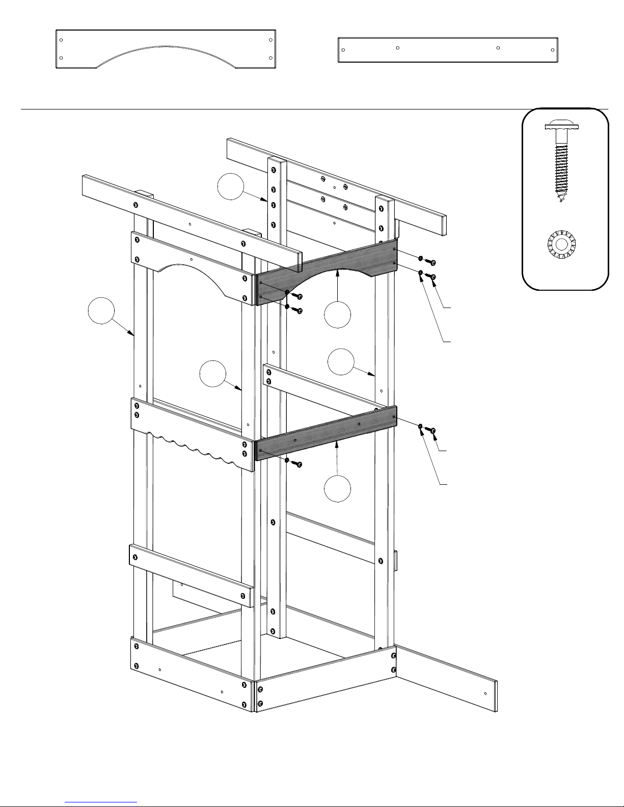
STEP 4
K2 - ARCH BOARD - W103812
(1)
5/8"x5 1/4"x30" (16x134x762)
E4
M5 - FLOOR RAIL - W103805
(1)
5/8"x3 3/8"x30" (16x86x762)
(6)
(6)
LAG SCREW
WH 5/16x2
WASHER
LOCK EXT
8x19
E3
E1
K2
E2
M5
LAG SCREW WH 5/16x2
(4 PLCS)
WASHER LOCK EXT 8x19
(4 PLCS)
LAG SCREW WH 5/16x2
(2 PLCS)
WASHER LOCK EXT 8x19
(2 PLCS)
Page 35
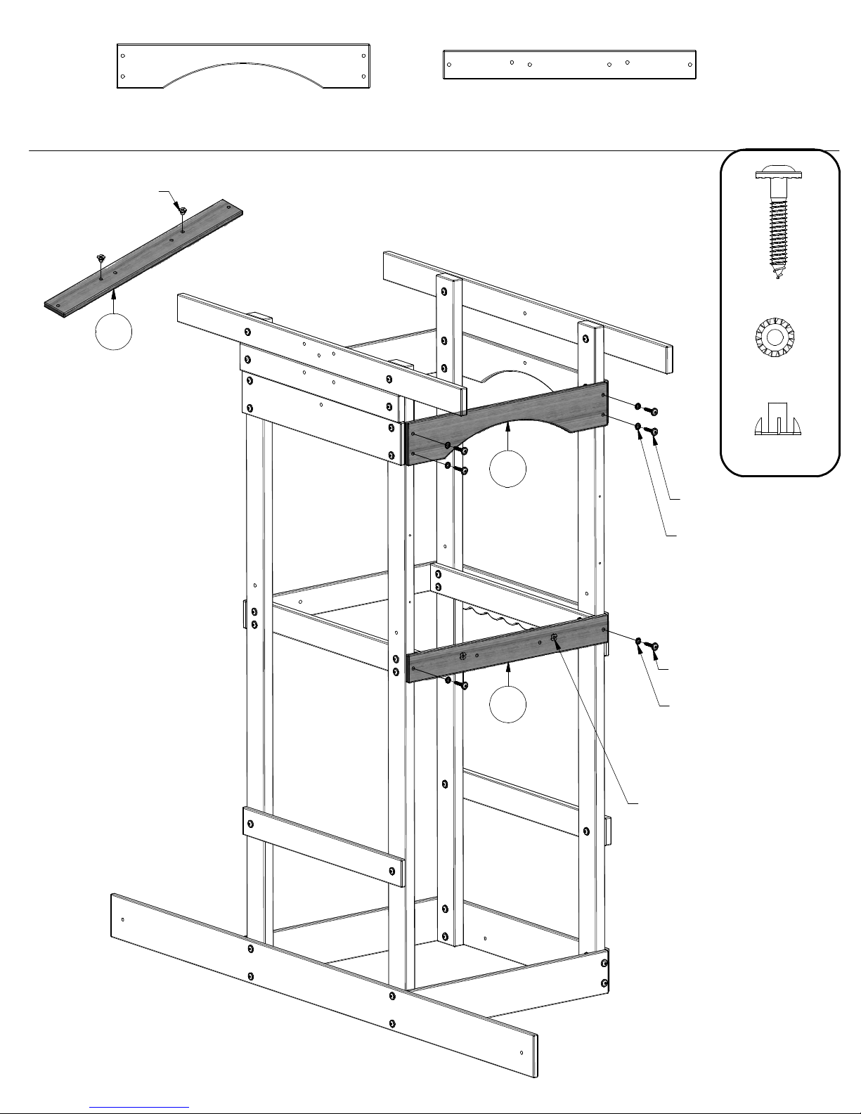
STEP 5
T-NUT 5/16
(2 PLCS)
M6
K2 - ARCH BOARD - W103812
(1)
5/8"x5 1/4"x30" (16x134x762)
M6 - FLOOR RAIL - W103806
(1)
5/8"x3 3/8"x30" (16x86x762)
K2
LAG SCREW
(6)
WH 5/16x2
WASHER
LOCK EXT
(6)
(2)
8x19
T-NUT 5/16
LAG SCREW WH 5/16x2
(4 PLCS)
WASHER LOCK EXT 8x19
(4 PLCS)
M6
LAG SCREW WH 5/16x2
(2 PLCS)
WASHER LOCK EXT 8x19
(2 PLCS)
T-NUTS SHOULD FACE
TOWARD THE OUTSIDE
OF THE FORT.
Page 36
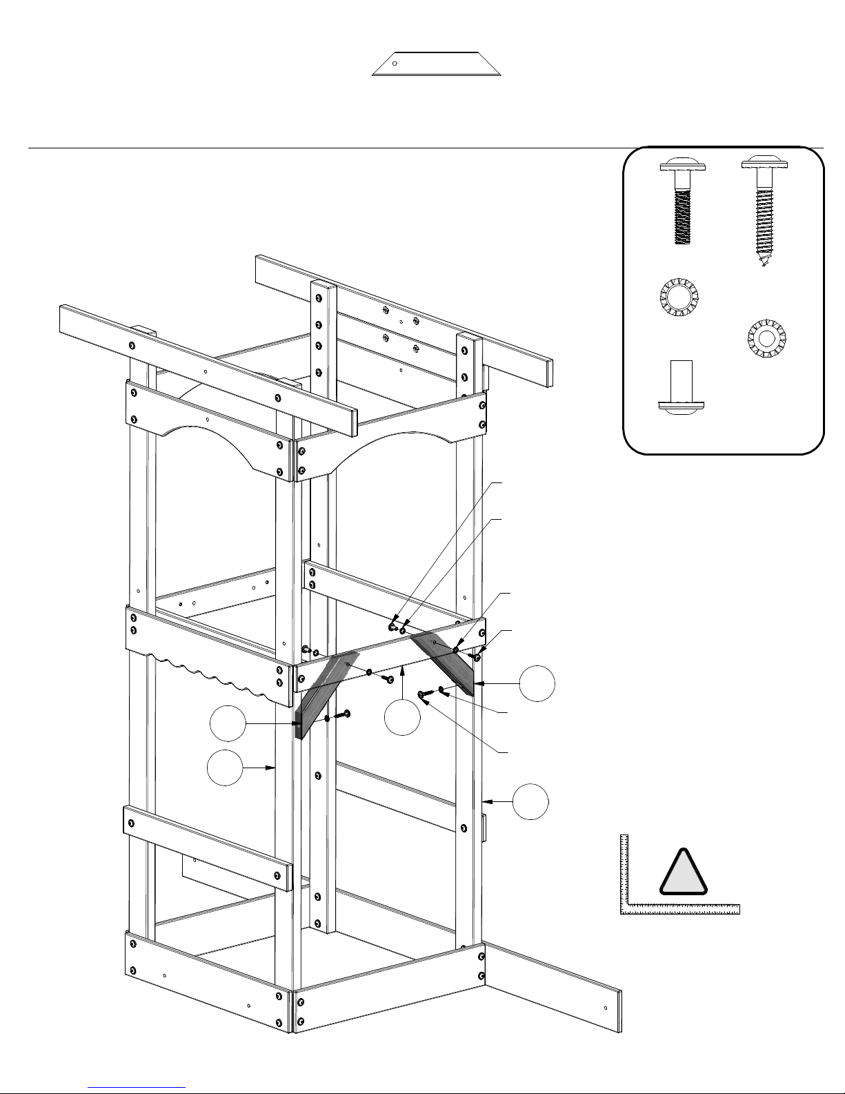
STEP 6
F71 - STANDARD ANGLE BRACE - W100689
(2)
1 3/8"x2 3/8"x13" (36x60x330)
(2)
(2)
(2)
NUT BARREL WH 5/16x7/8
(2 PLCS)
WASHER LOCK EXT 12x19
(2 PLCS)
BOLT WH
5/16x1-1/2
(2)
WASHER
LOCK EXT
12x19
NUT BARREL
WH 5/16x7/8
LAG SCREW
WH 5/16x2
(4)
WASHER
LOCK EXT
8x19
F71
E1
M5
WASHER LOCK EXT 8x19
(2 PLCS)
BOLT WH 5/16x1-1/2
(2 PLCS)
F71
WASHER LOCK EXT 8x19
(2 PLCS)
LAG SCREW WH 5/16x2
(2 PLCS)
E2
3
151
4
2
1
1
3
1
1
1
2
0
1
1
1
1
9
0
1
8
9
7
6
8
7
5
4
6
5
3
4
2
3
1
2
3
2
4
1
1
2
34567
1
!
2221201
9
17161
5
1
3
6
5
89101
1
1213141
1
4
121110987
5
1
8
161718192021222
3
Page 37
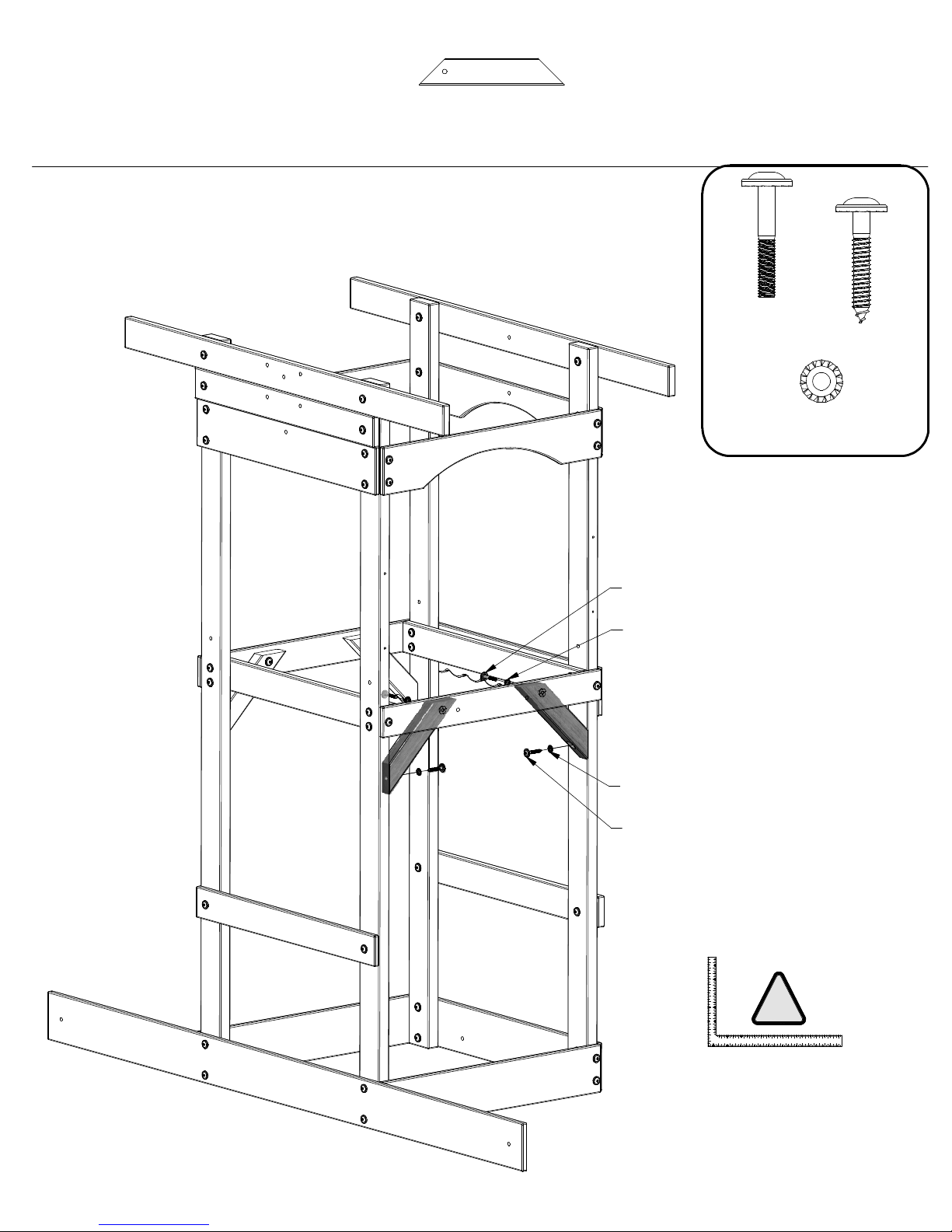
STEP 7
F71 - STANDARD ANGLE BRACE - W100689
(2)
1 3/8"x2 3/8"x13" (36x60x330)
(2)
BOLT WH
5/16x2
(4)
LAG SCREW
(2)
WH 5/16x2
WASHER
LOCK EXT
8x19
BOLT WH 5/16x2
(2 PLCS)
WASHER LOCK EXT 8x19
(2 PLCS)
WASHER LOCK EXT 8x19
(2 PLCS)
LAG SCREW WH 5/16x2
(2 PLCS)
5
3
1
1
4
2
1
1
3
1
1
1
2
0
1
1
1
1
9
0
1
8
7
9
6
8
7
5
4
6
5
3
2
4
3
1
2
1
1
12345678910111213141516
!
2
222120191817161514131211109876543
222
3
1
8
2
021
1
9
1
7
Page 38
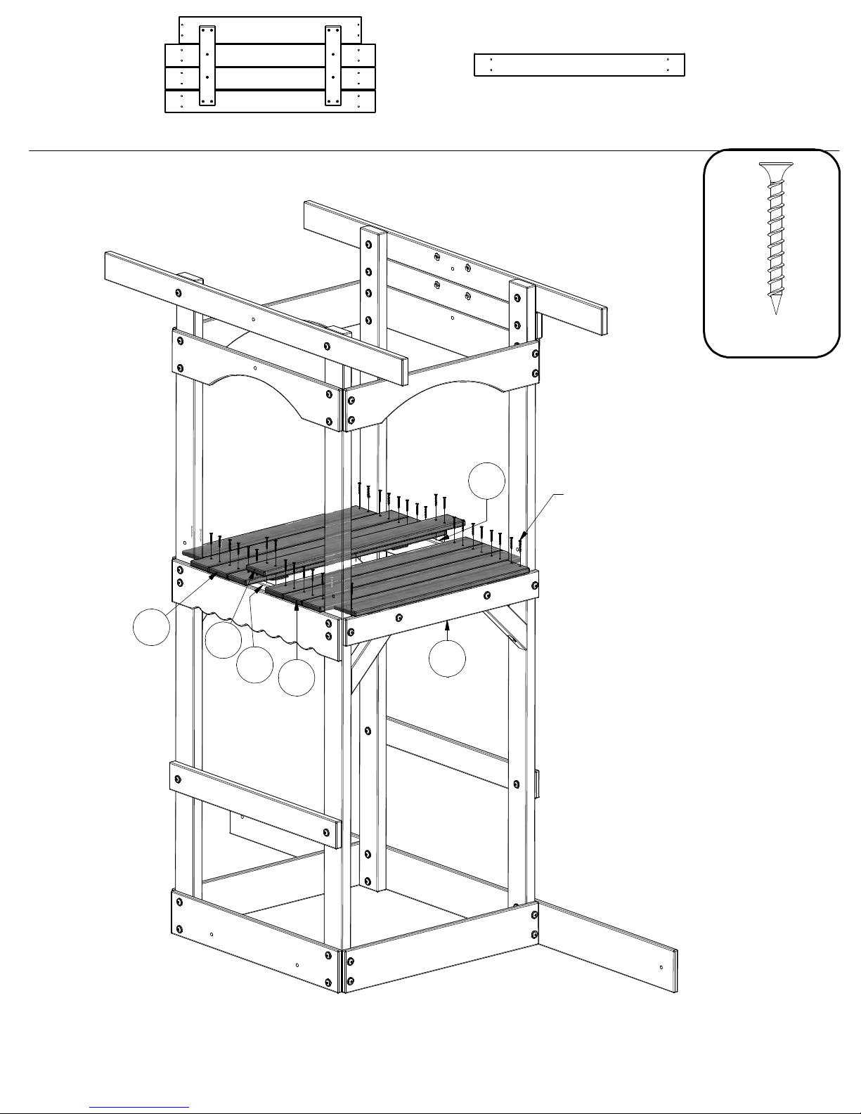
STEP 8
(2)
FP1 - FLOOR PANEL - W103821
M9 - FLOOR BOARD - W103822
(1)
5/8"x3 3/8"x31 1/4" (16x86x794)
(36)
SCREW PFH
8x1-1/2
FP1
M9
H1
H1
SCREW PFH 8x1-1/2
(36 PLCS)
M5
FP1
Page 39
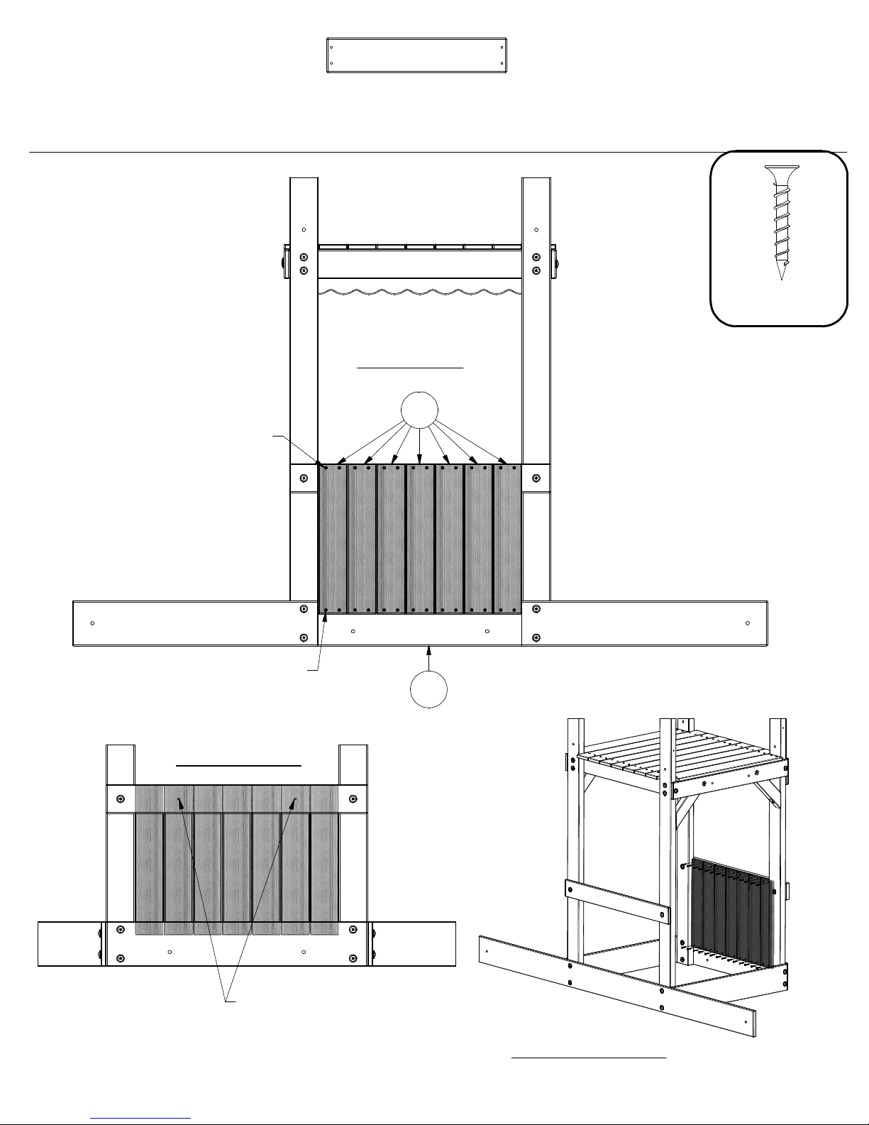
STEP 9
SCREW PFH 8x1-1/8
(14 PLCS)
M3 - FLOOR BOARD - W103824
(7)
5/8"x3 3/8"x17 5/8" (16x86x448)
INSIDE VIEW
M3
(28)
SCREW PFH
8x1-1/8
SCREW PFH 8x1-1/8
(14 PLCS)
OUTSIDE VIEW
USING A 1/8" DRILL BIT,
DRILL DESIGNATED HOLES
THROUGH 'M3' BOARDS.
K3
REFERENCE VIEW
Page 40
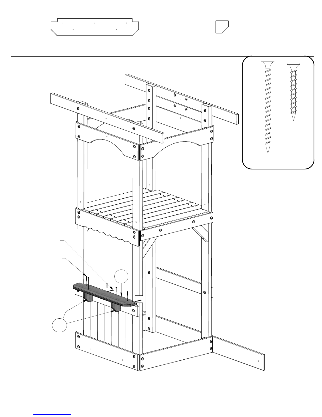
STEP 10
K7 - LEMONADE SHELF - W103825
(1)
5/8"x5 1/4"x27 7/8" (16x134x708)
H10 - SHELF SUPPORT - W103961
(2)
1"x3 3/8"x3 3/8" (24x86x86)
(2)
(5)
SCREW PFH
8x2-1/2
SCREW PFH
8x1-1/2
SCREW PFH 8x2-1/2
(2 PLCS)
SCREW PFH 8x1-1/2
(5 PLCS)
H10
K7
Page 41
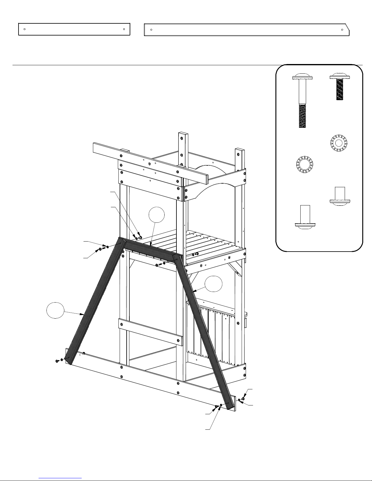
(1)
STEP 11
NUT BARREL WH 5/16x7/8
M8 - WALL RAIL - W103813
5/8"x3 3/8"x30 3/4" (16x86x780)
(2 PLCS)
WASHER LOCK EXT 12x19
(2 PLCS)
M8
M11 - ANGLE BRACE - W103826
(2)
5/8"x3 3/8"x56 3/8" (16x86x1431)
(2)
(4)
BOLT WH
5/16x2-1/4
WASHER
LOCK EXT
12x19
(2)
(4)
NUT BARREL
(2)
WH 5/16x5/8
BOLT WH
5/16x1
WASHER
LOCK EXT
8x19
WASHER LOCK EXT 8x19
(2 PLCS)
BOLT WH 5/16x2-1/4
(2 PLCS)
M11
BOLT WH 5/16x1
(2 PLCS)
WASHER LOCK EXT 8x19
(2 PLCS)
M11
NUT BARREL
(2)
WH 5/16x7/8
NUT BARREL WH 5/16x5/8
(2 PLCS)
WASHER LOCK EXT 12x19
(2 PLCS)
Page 42
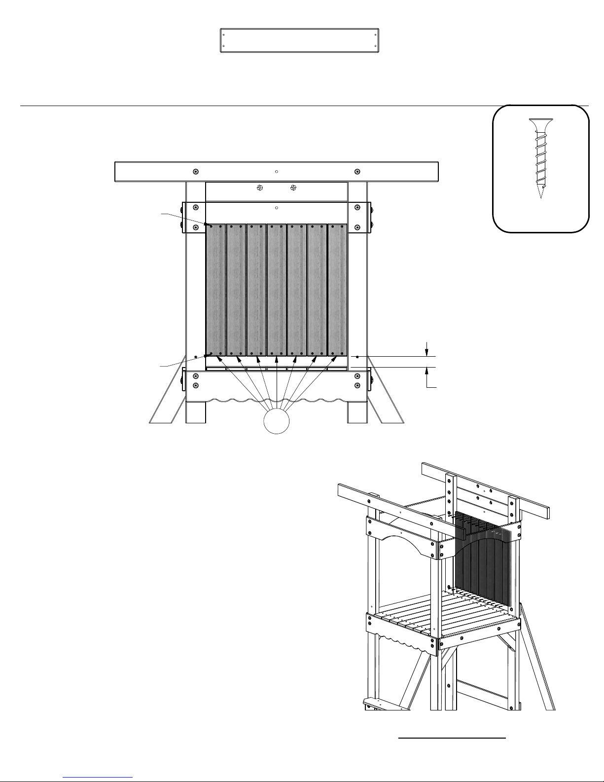
STEP 12
SCREW PFH 8x1-1/8
(14 PLCS)
M4 - FLOOR BOARD - W103823
(7)
5/8"x3 3/8"x22 3/8" (16x86x568)
(28)
SCREW PFH
8x1-1/8
SCREW PFH 8x1-1/8
(14 PLCS)
1 13/16"
M4
REFERENCE VIEW
Page 43
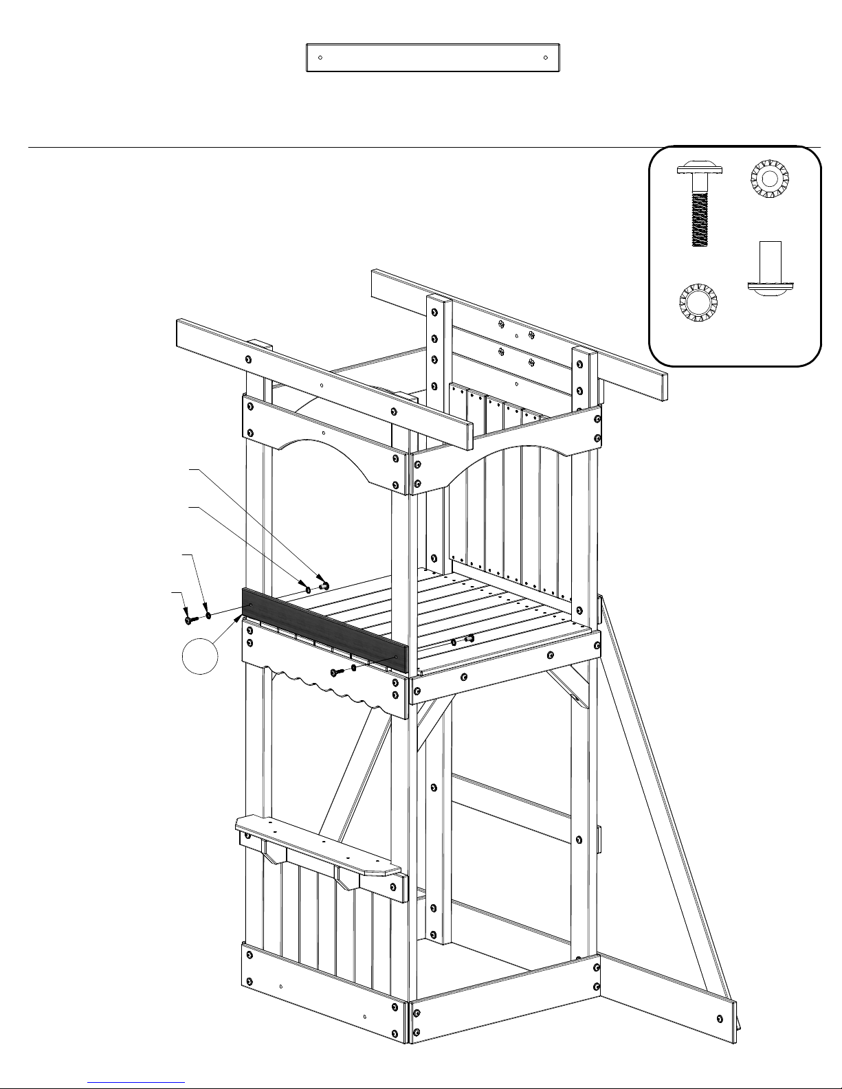
STEP 13
NUT BARREL WH 5/16x7/8
(2 PLCS)
WASHER LOCK EXT 12x19
(2 PLCS)
M8 - WALL RAIL - W103813
(1)
5/8"x3 3/8"x30 3/4" (16x86x780)
(2)
(2)
(2)
BOLT WH
5/16x1-1/2
(2)
WASHER
LOCK EXT
12x19
WASHER
LOCK EXT
8x19
NUT BARREL
WH 5/16x7/8
WASHER LOCK EXT 8x19
(2 PLCS)
BOLT WH 5/16x1-1/2
(2 PLCS)
M8
Page 44
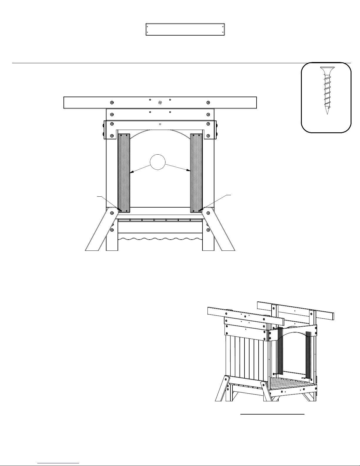
STEP 14
M4 - FLOOR BOARD - W103823
(2)
5/8"x3 3/8"x22 3/8" (16x86x568)
M4
(8)
SCREW PFH
8x1-1/8
SCREW PFH 8x1-1/8
(4 PLCS)
SCREW PFH 8x1-1/8
(4 PLCS)
REFERENCE VIEW
Page 45
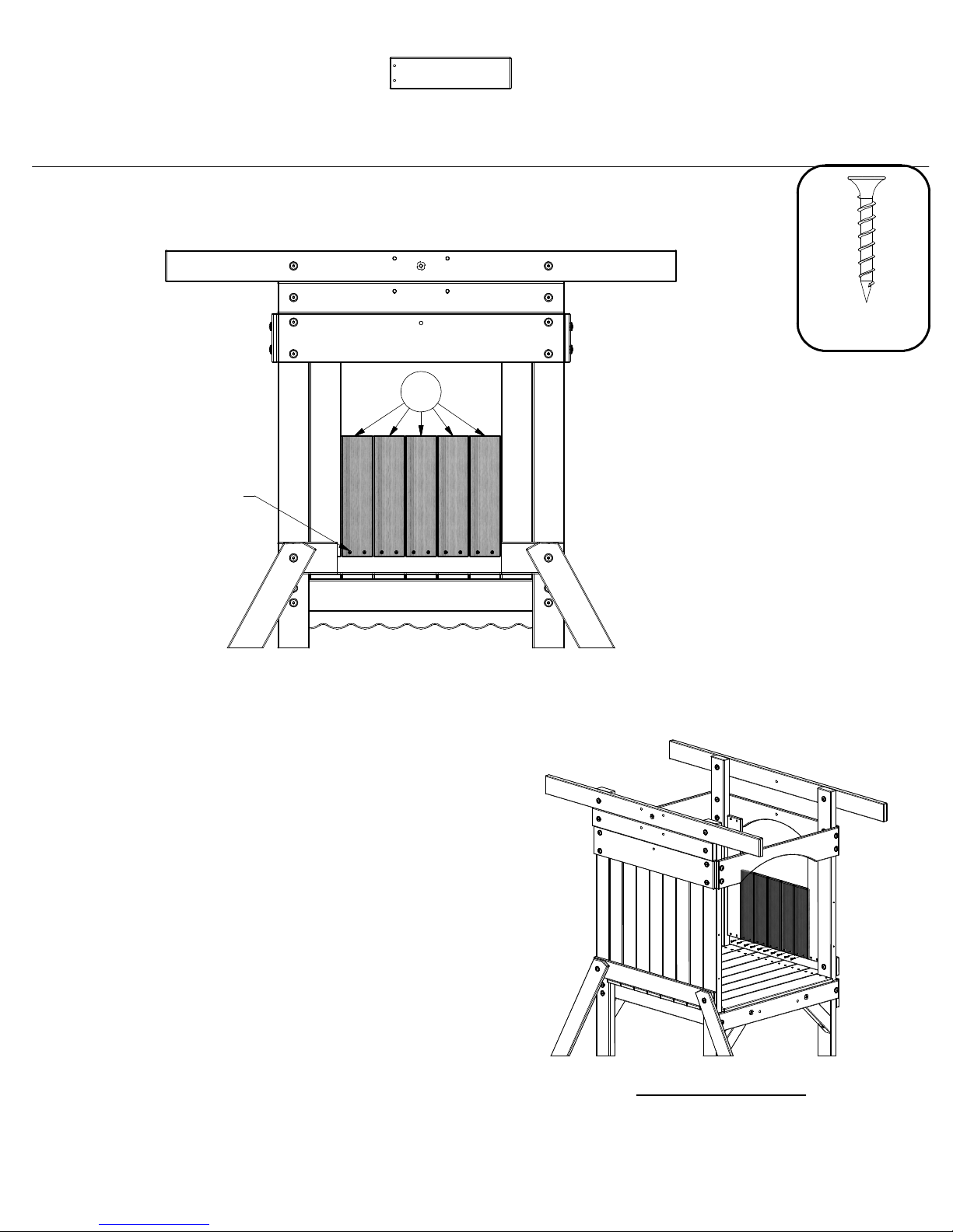
STEP 15
SCREW PFH 8x1-1/8
(10 PLCS)
M1 - WALL BOARD - W103827
(5)
5/8"x3 3/8"x13" (16x86x330)
M1
(10)
SCREW PFH
8x1-1/8
REFERENCE VIEW
Page 46
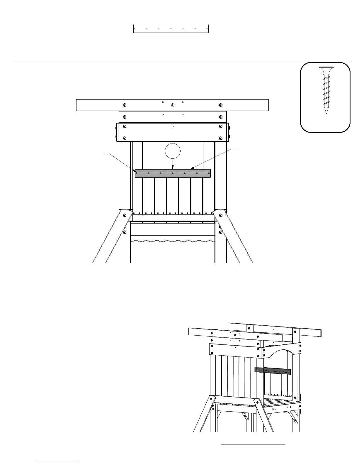
STEP 16
N1 - WINDOW BOARD - W103828
(1)
5/8"x2 3/8"x21 1/2" (16x60x546)
(7)
SCREW PFH
8x1-1/8
SCREW PFH 8x1-1/8
(7 PLCS)
N1
FLUSH
REFERENCE VIEW
Page 47
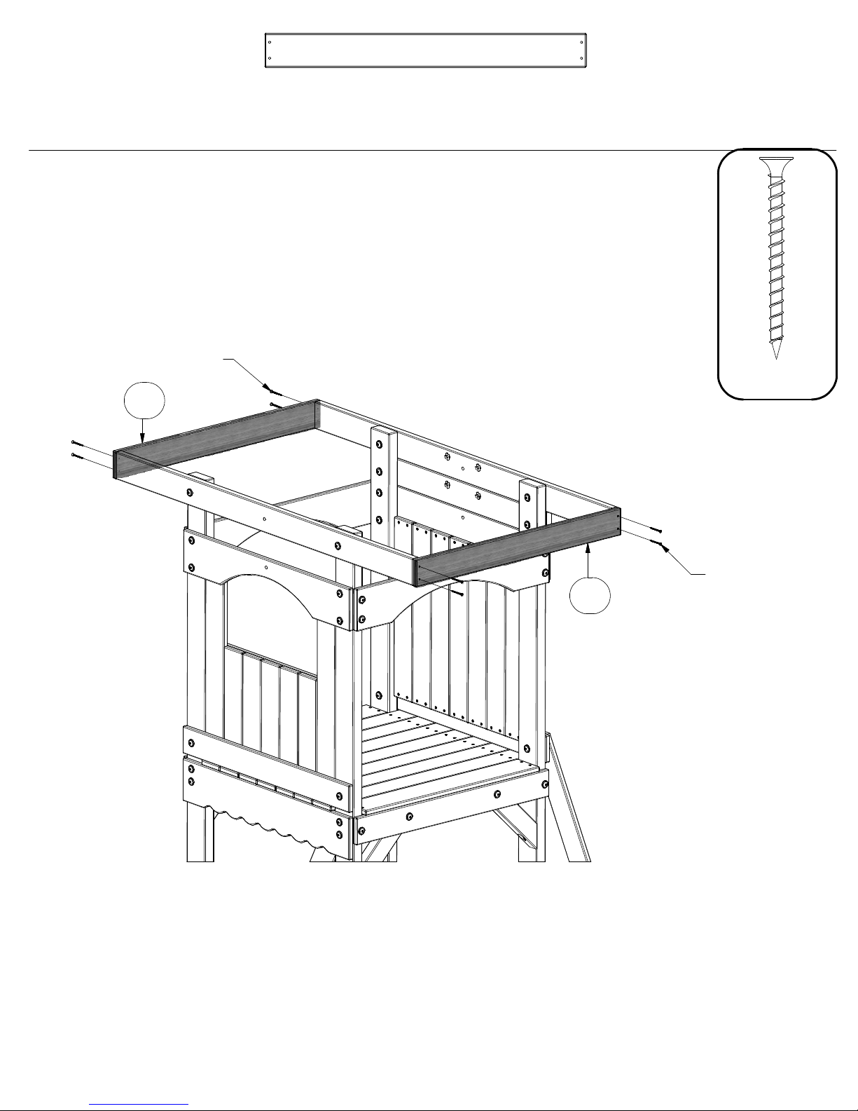
STEP 17
M10 - END TARP SUPPORT - W103817
(2)
5/8"x3 3/8"x31 7/8" (16x86x810)
SCREW PFH 8x2
(4 PLCS)
M10
M10
SCREW PFH
(8)
8x2
SCREW PFH 8x2
(4 PLCS)
Page 48
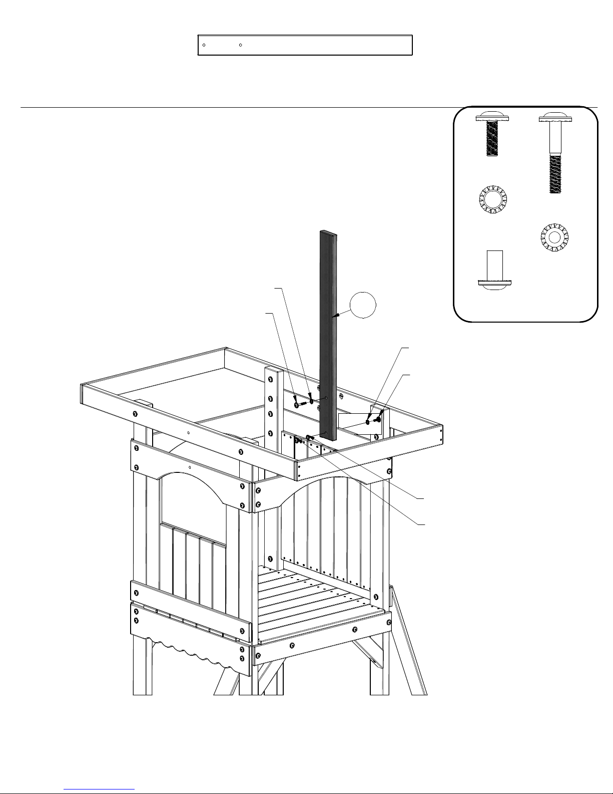
STEP 18
H7 - VERTICAL TARP SUPPORT - W103819
(1)
1"x3 3/8"x35 7/8" (24x86x910)
WASHER LOCK EXT 8x19
(1 PLC)
BOLT WH 5/16x2
(1 PLC)
H7
BOLT WH
(1)
(1)
(1)
5/16x1
WASHER
LOCK EXT
12x19
NUT BARREL
WH 5/16x7/8
WASHER LOCK EXT 8x19
(1 PLC)
BOLT WH 5/16x1
(1 PLC)
(1)
(2)
BOLT WH
5/16x2
WASHER
LOCK EXT
8x19
WASHER LOCK EXT 12x19
(1 PLC)
NUT BARREL WH 5/16x7/8
(1 PLC)
Page 49
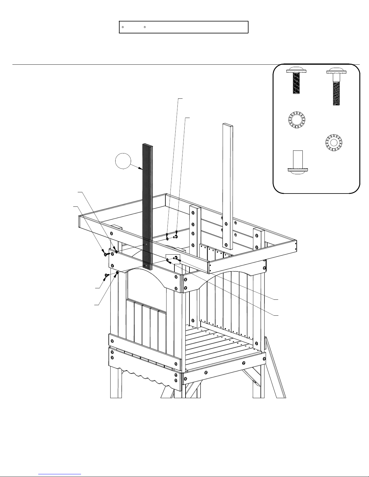
STEP 19
H7 - VERTICAL TARP SUPPORT - W103819
(1)
1"x3 3/8"x35 7/8" (24x86x910)
WASHER LOCK EXT 8x19
(1 PLC)
BOLT WH 5/16x1-1/2
(1 PLC)
H7
WASHER LOCK EXT 12x19
(1 PLC)
NUT BARREL WH 5/16x7/8
(1 PLC)
(1)
(2)
NUT BARREL
(2)
WH 5/16x7/8
BOLT WH
5/16x1
WASHER
LOCK EXT
12x19
(2)
(1)
BOLT WH
5/16x1-1/2
WASHER
LOCK EXT
8x19
BOLT WH 5/16x1
(1 PLC)
WASHER LOCK EXT 8x19
(1 PLC)
NUT BARREL WH 5/16x7/8
(1 PLC)
WASHER LOCK EXT 12x19
(1 PLC)
Page 50
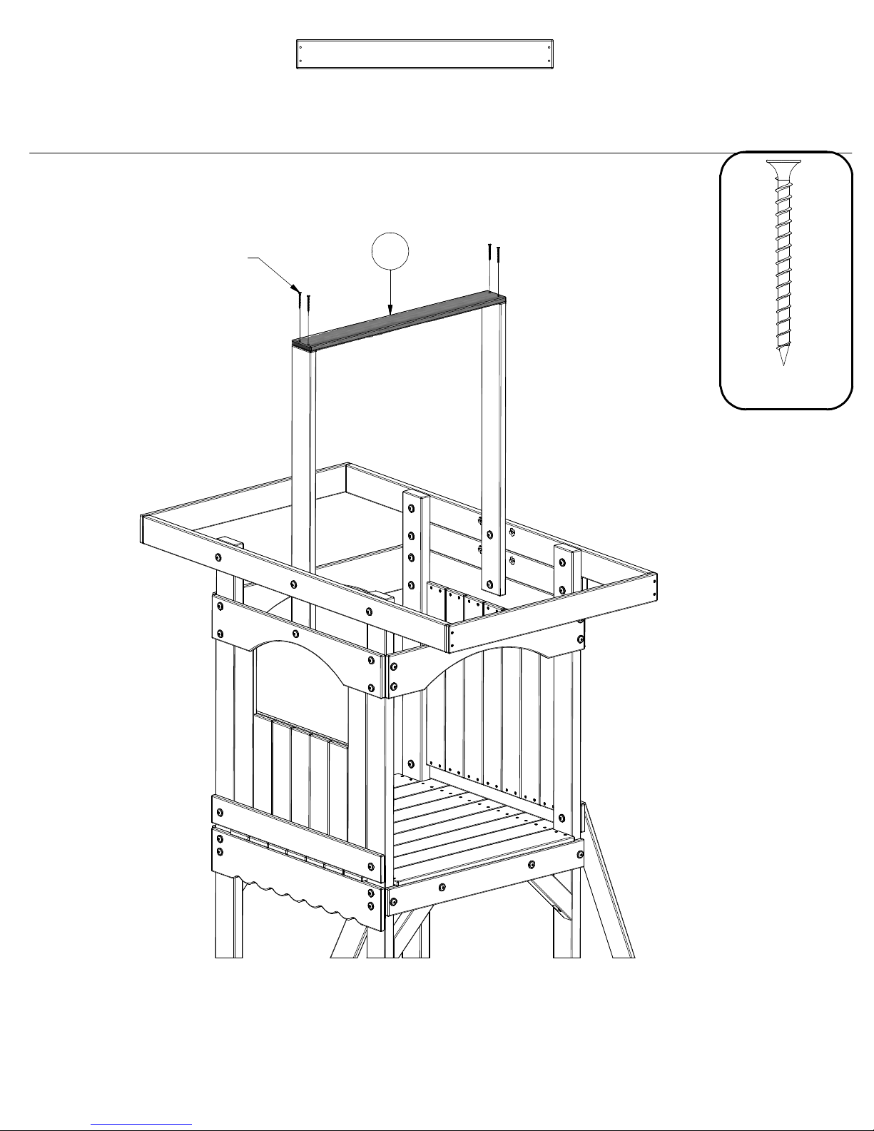
STEP 20
M7 - TOP TARP SUPPORT - W103820
(1)
5/8"x3 3/8"x30" (16x86x762)
SCREW PFH 8x2
(4 PLCS)
M7
(4)
SCREW PFH
8x2
Page 51
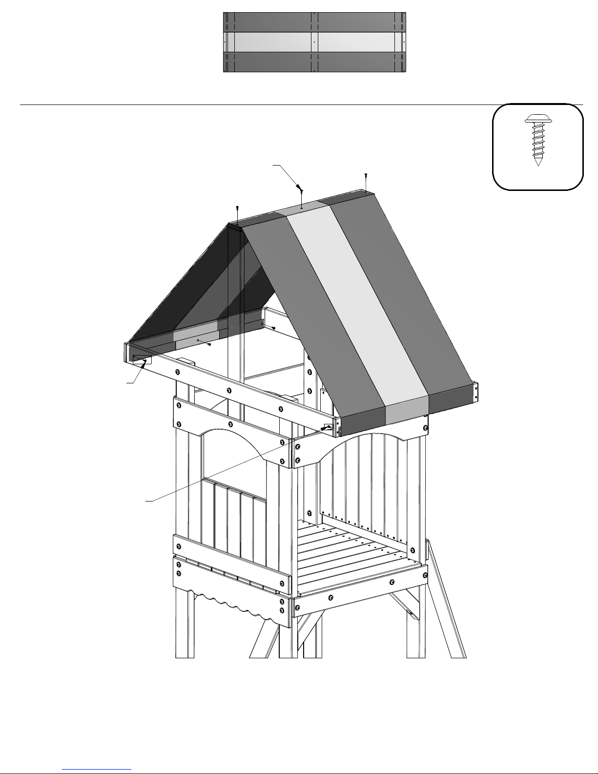
STEP 21
WT - TARP .4x752x2309 - A100398
(1)
1/64"x29 5/8"x90 7/8" (.4x752x2309)
SCREW PWH 8x5/8
(3 PLCS)
SCREW PWH 8x5/8
(3 PLCS)
SCREW PWH
(9)
8x5/8
SCREW PWH 8x5/8
(3 PLCS)
Page 52
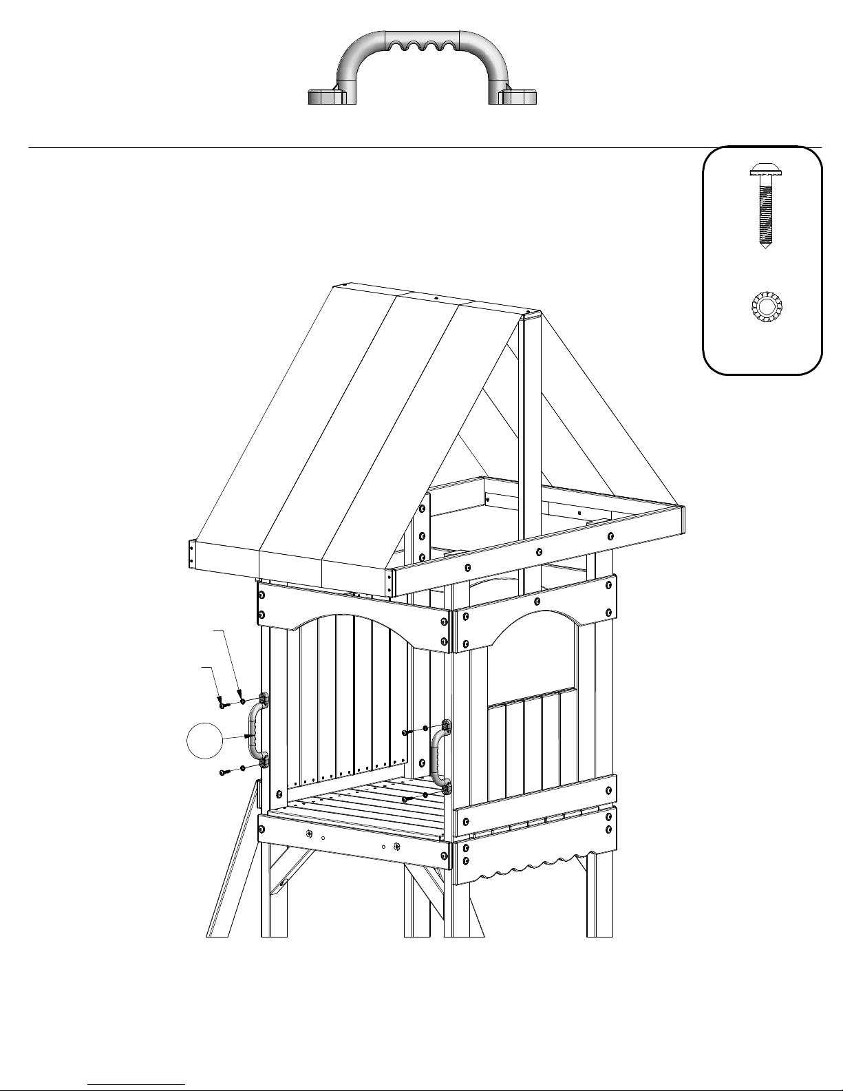
STEP 22
(2)
EA - HAND GRIP YELLOW PLASTIC - A100043
(4)
(4)
LAG SCREW
WH 1/4x1-1/2
WASHER
LOCK EXT
6x15
WASHER LOCK EXT 6x15
(4 PLCS)
LAG SCREW WH 1/4x1-1/2
(4 PLCS)
EA
Page 53
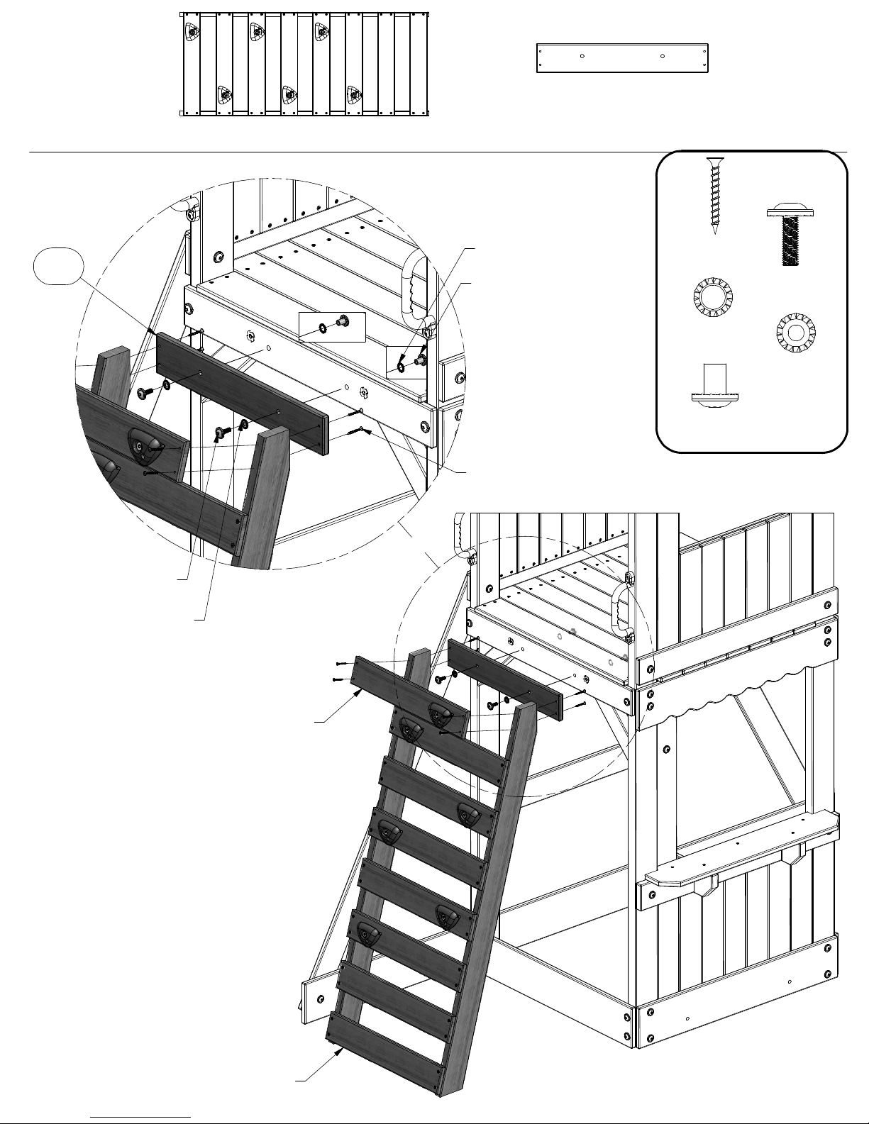
STEP 23
(1)
4 FT ROCK LADDER
M102 - ATTACHMENT BOARD - W103690
(1)
5/8"x3 3/8"x20 1/4" (16x86x514)
M102
BOLT WH 5/16x1
(2 PLCS)
WASHER LOCK EXT 8x19
(2 PLCS)
WASHER LOCK EXT 12x19
(2 PLCS)
NUT BARREL WH 5/16x5/8
(2 PLCS)
SCREW PFH 8x1-1/2
(4 PLCS)
SCREW PFH
(4)
(2)
NUT BARREL
(2)
WH 5/16x5/8
8x1-1/2
(2)
WASHER
LOCK EXT
12x19
(2)
BOLT WH
5/16x1
WASHER
LOCK EXT
8x19
This rung may need to be
temporarily removed to aid
in rock ladder installation.
4 FT ROCK LADDER ASSEMBLY
Page 54
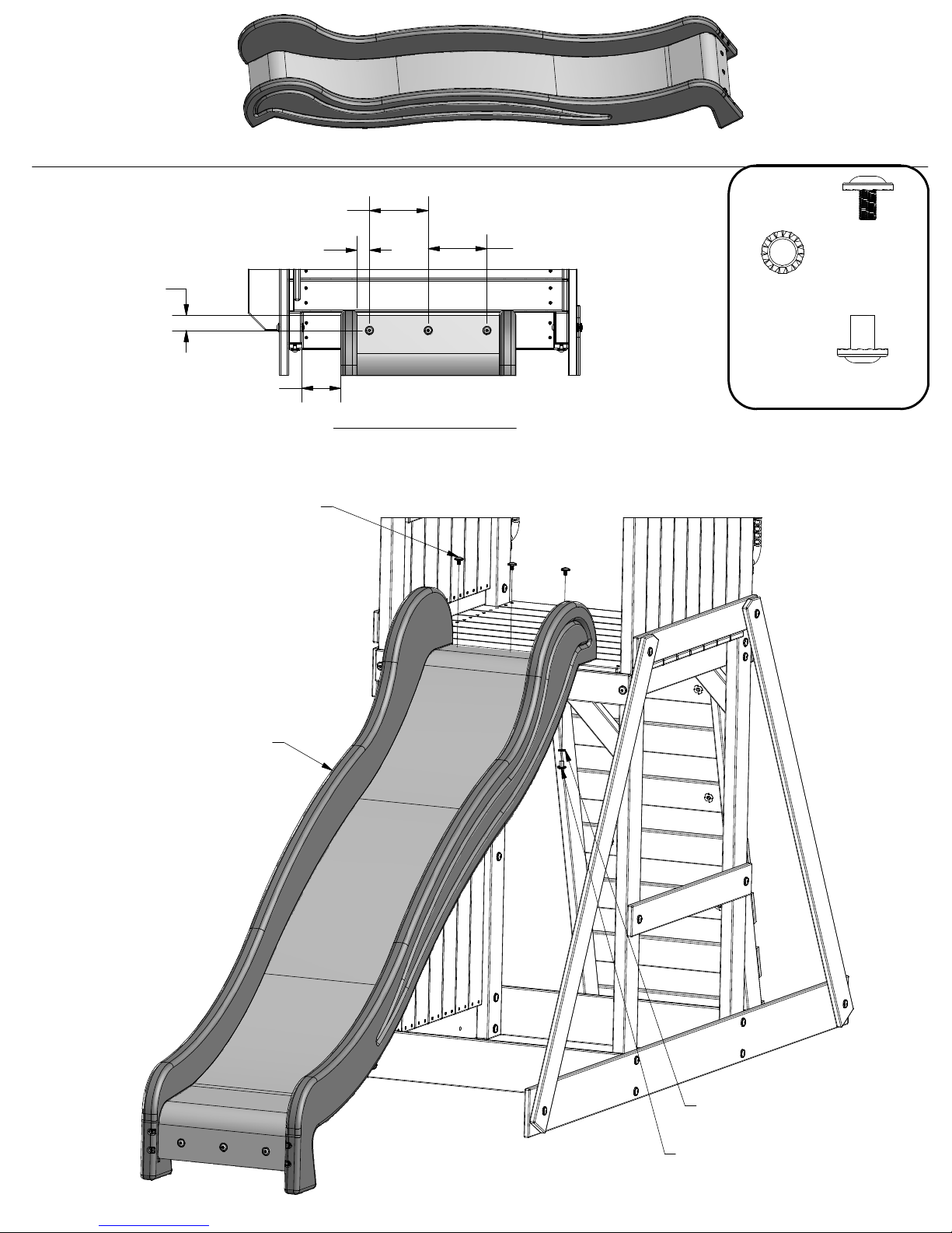
STEP 24
6 5/16"
1 5/16"
(1) 8
FT SLIDE ASSEMBLY
6 5/16"
(3)
BOLT WH
5/16x1/2
1 9/16"
4 3/16"
BOLT WH 5/16x1/2
(3 PLCS)
DRILLING PATTERN
(3)
WASHER
LOCK EXT
12x19
(3)
NUT BARREL
WH 5/16x5/8
8 FT SLIDE ASSEMBLY
WASHER LOCK EXT 12x19
(3 PLCS)
NUT BARREL WH 5/16x5/8
(3 PLCS)
Page 55
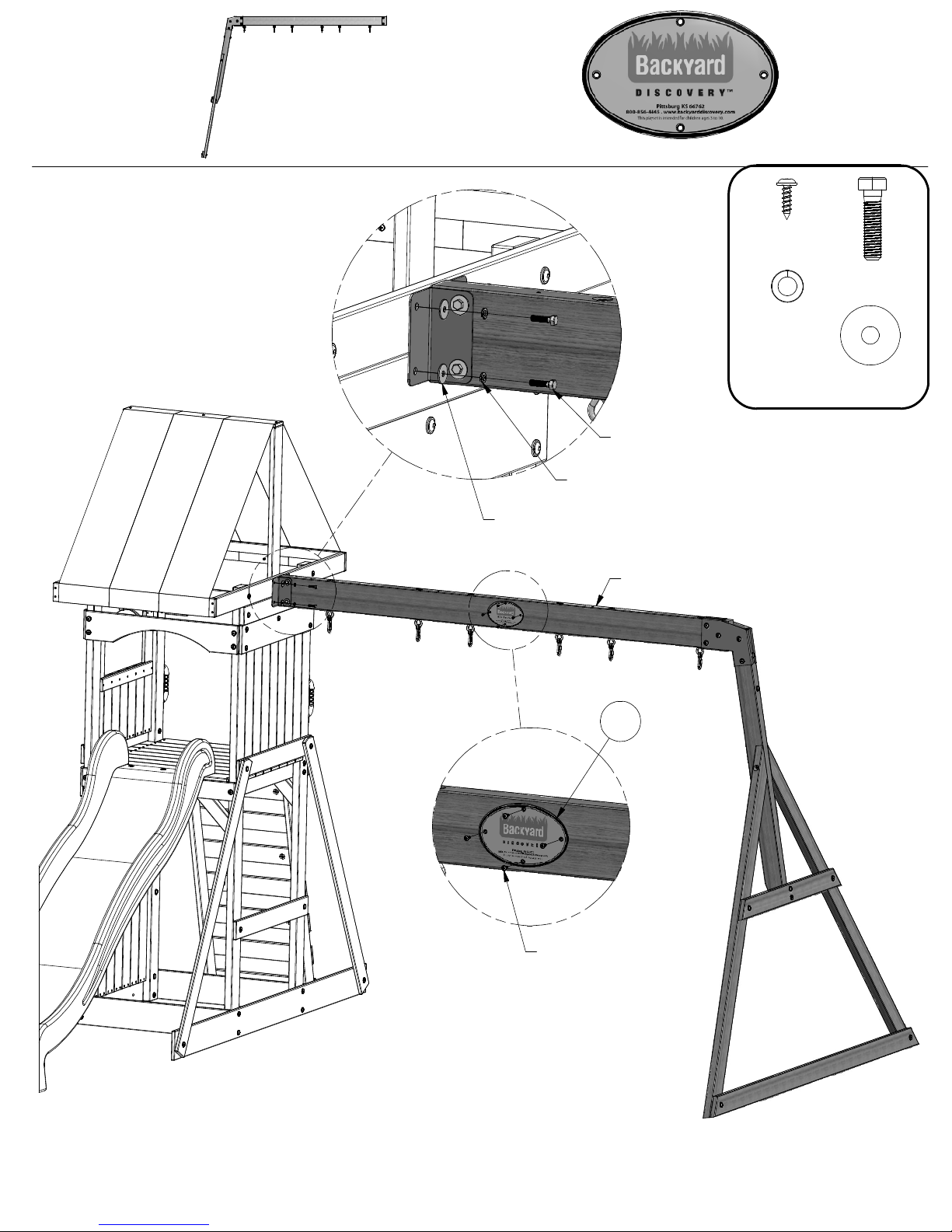
STEP 25
(1) 8
FT SLIDE ASSEMBLY
(1)
HC - BYD ID TAG (LARGE) 2011 WITH AGES - A100164
(4)
(4)
BOLT HEX 5/16x1-1/4
(4 PLCS)
WASHER SPLIT 5/16
(4 PLCS)
WASHER FLAT 8x27
(4 PLCS)
SCREW PWH
8x5/8
(4)
WASHER
SPLIT 5/16
(4)
BOLT HEX
5/16x1-1/4
WASHER
FLAT 8x27
4 FT SWING BEAM ASSEMBLY
HC
SCREW PWH 8x5/8
(4 PLCS)
Page 56
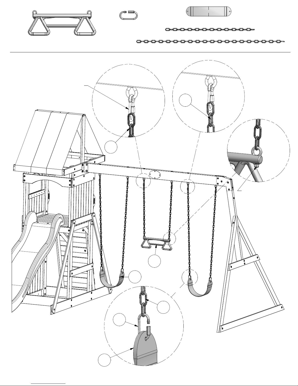
(1)
TN - TRAPEZE WITH HARDWARE YELLOW - A100334
STEP 26
SWING HANGER QUICK LINK
(6 PLCS)
(4)
FA - QUICK LINK - A100069
KN
(2)
FB - SWING SEAT YELLOW - A100070
(2)
KN - CHAIN GREEN 31" - A100177
(4)
EZ - CHAIN GREEN 51.25" - A100068
EZ
FA
FB
LOOSEN NUT AND
LIFT EYE BOLT TO
INSERT CHAIN.
TN
EZ
FB
Page 57
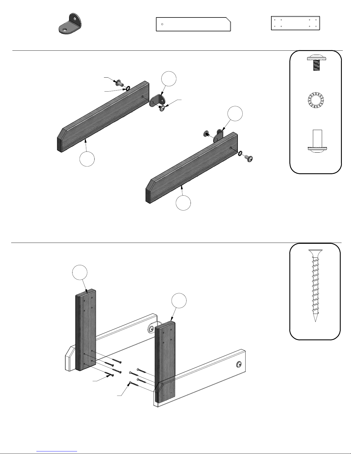
(2)
ES - L BRACKET GREEN 32x51 - A100061
STEP 27
H6 - BENCH GROUND BOARD - W104042
(2)
1"x3 3/8"x18 1/8" (24x86x460)
H5 - BENCH UPRIGHT - W104041
(2)
1"x3 3/8"x11 3/4" (24x86x300)
NUT BARREL WH 5/16x7/8
(2 PLCS)
WASHER LOCK EXT 12x19
(2 PLCS)
H6
ES
BOLT WH 5/16x1/2
(2 PLCS)
H6
ES
(2)
(2)
NUT BARREL
(2)
WH 5/16x7/8
BOLT WH
5/16x1/2
WASHER
LOCK EXT
12x19
STEP 28
H5
SCREW PFH 8x1-3/4
(4 PLCS)
SCREW PFH 8x1-3/4
(4 PLCS)
H5
(8)
SCREW PFH
8x1-3/4
Page 58
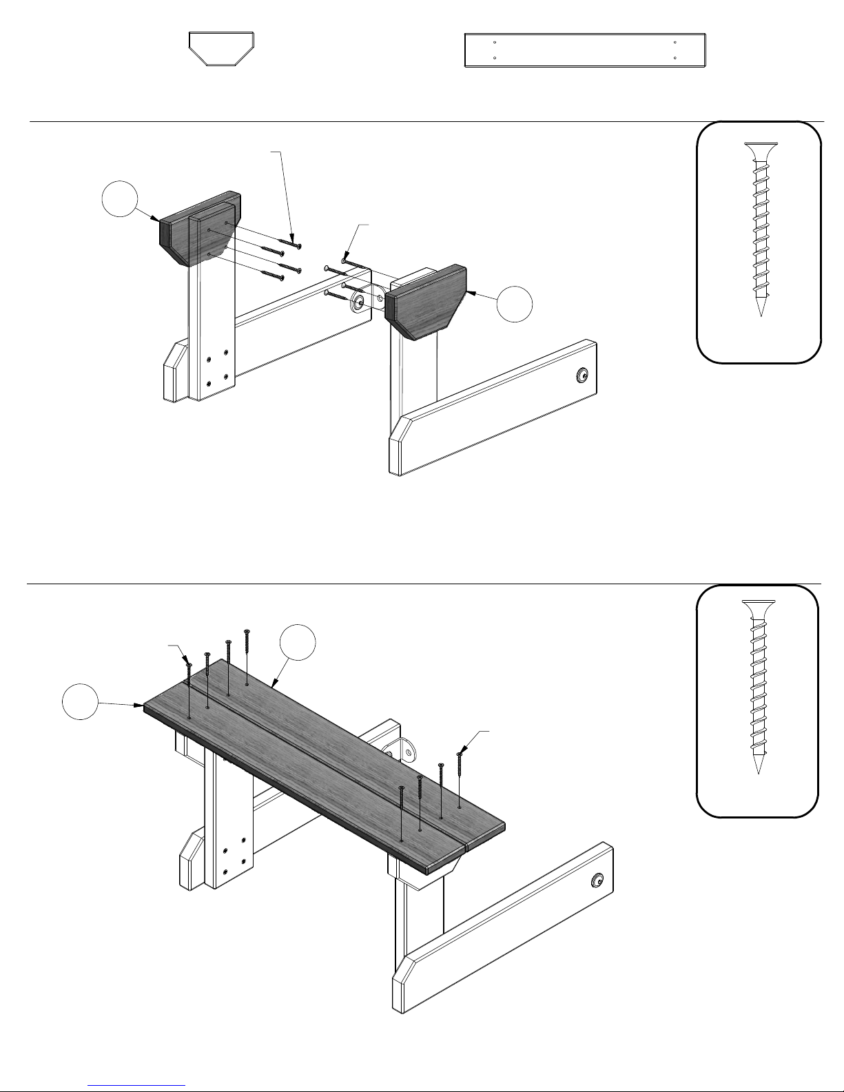
STEP 29
H4 - BENCH SEAT SUPPORT - W104040
(2)
1"x3 3/8"x6 1/2" (24x86x166)
SCREW PFH 8x1-3/4
(4 PLCS)
H4
SCREW PFH 8x1-3/4
(4 PLCS)
M2 - BENCH SEAT - W104043
(2)
5/8"x3 3/8"x24 3/8" (16x86x618)
H4
(8)
SCREW PFH
8x1-3/4
STEP 30
SCREW PFH 8x1-3/4
(4 PLCS)
M2
M2
SCREW PFH 8x1-3/4
(4 PLCS)
(8)
SCREW PFH
8x1-3/4
Page 59
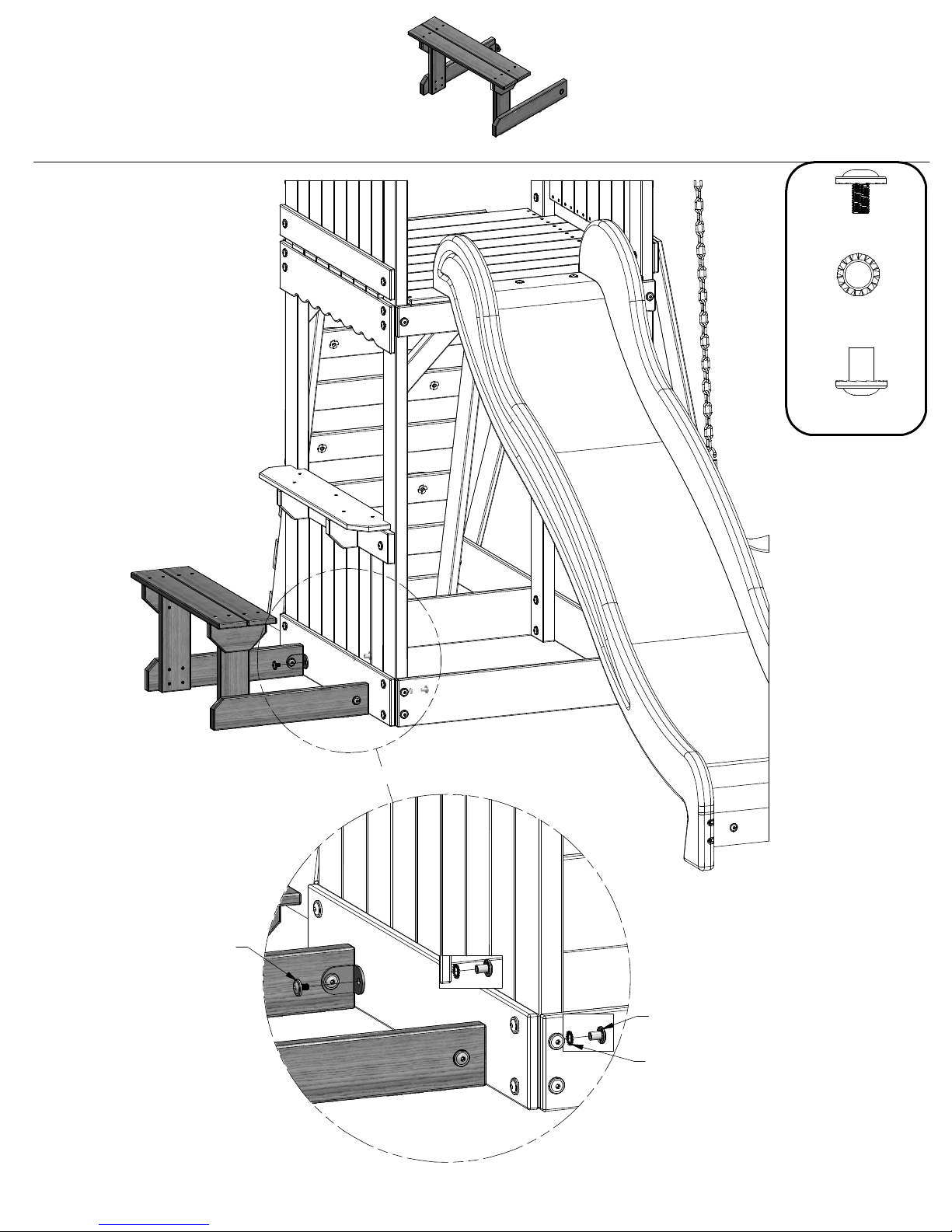
STEP 31
(1)
BENCH ASSEMBLY
(2)
(2)
(2)
BOLT WH
5/16x1/2
WASHER
LOCK EXT
12x19
NUT BARREL
WH 5/16x5/8
BOLT WH 5/16x1/2
(2 PLCS)
NUT BARREL WH 5/16x5/8
(2 PLCS)
WASHER LOCK EXT 12x19
(2 PLCS)
Page 60
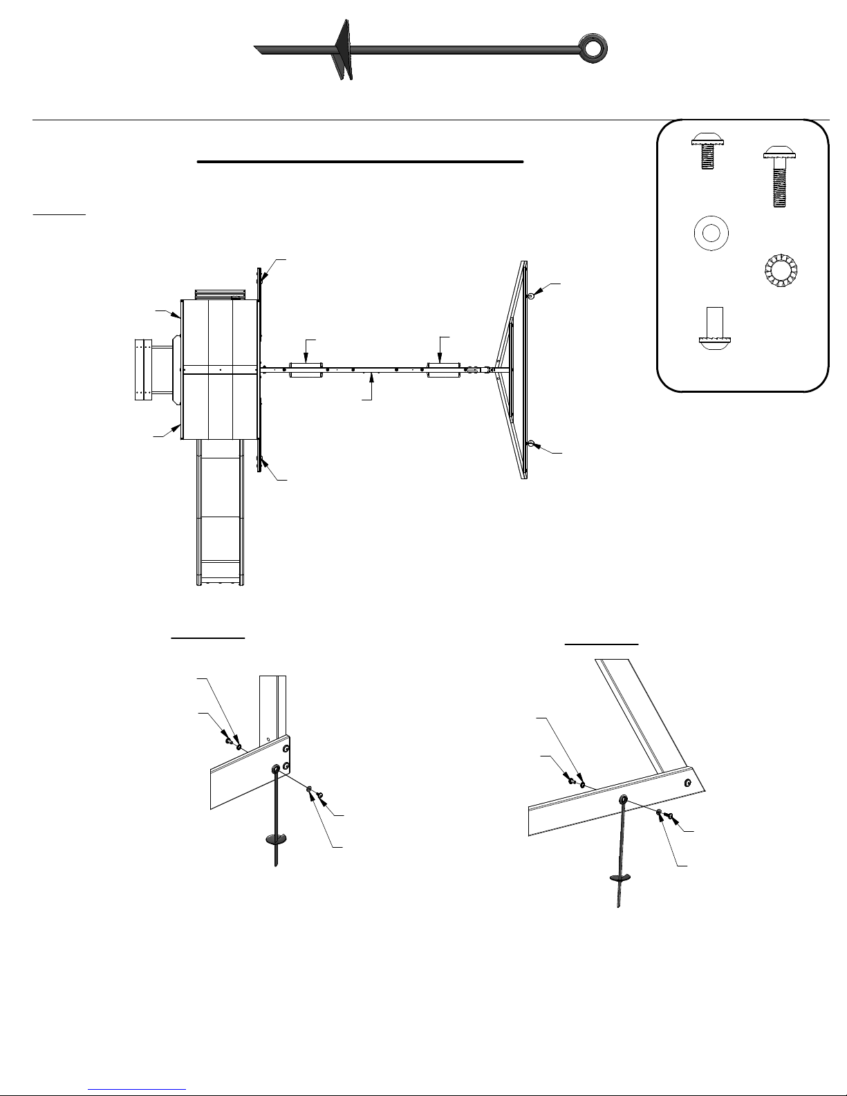
(6)
KC - METAL GROUND STAKE BROWN - A100178
Anchoring Instructions
STEP 32
NOTE:
FAILURE TO USE GROUND STAKES CAN VOID WARRANTY & CAUSE INJURY!
STAKE A
STAKE A
SWING
TRAPEZE
STAKE A
STAKE A
SWING
STAKE B
STAKE B
(4)
(6)
NUT BARREL
(6)
BOLT WH
1/4x1/2"
(2)
WASHER
FLAT 9x18
(6)
WH 1/4x5/8"
BOLT WH
1/4x1"
WASHER
LOCK EXT
8x15
STAKE A
STAKE B
WASHER LOCK EXT 8x15
(4 PLCS)
NUT BARREL WH 1/4x5/8"
(4 PLCS)
WASHER LOCK EXT 8x15
(2 PLCS)
NUT BARREL WH 1/4x5/8"
(2 PLCS)
BOLT WH 1/4x1/2"
(4 PLCS)
WASHER FLAT 9x18
(4 PLCS)
BOLT WH 1/4x1"
(2 PLCS)
WASHER FLAT 9x18
(2 PLCS)
FINAL STEP
DOUBLE CHECK EVERY BOLT, SCREW AND NUT FOR TIGHTNESS. MAKE SURE EVERY BOARD IS SECURE AND
MAKE SURE THE PLAY SET IS LEVEL.
ENJOY YOUR NEW PLAY SET!
Page 61

Limited Warranty
This Limited Warranty by Backyard Discovery applies to products manufactured under the Backyard Discovery
brand or its other brands including but not limited to Backyard Botanical, Adventure Playsets, and Leisure Time
Products.
Backyard Discovery warrants that this product is free from defect in materials and workmanship for a period of
one (1) year from the original date of purchase. This one (1) year warranty covers all parts including wood,
hardware, and accessories. All wood carries a five (5) year pro-rated warranty against rot and decay. Refer to
the schedule below for charges associated with replacement of parts under this Limited Warranty. In addition,
Backyard Discovery will replace any parts within the first 30 days from date of purchase found to be missing
from or damaged in the original packaging.
This warranty applies to the original owner and registrant and is non-transferable. Regular maintenance is
required to assure maximum life and performance of this product and failure by the owner to maintain the
product according to the maintenance requirements may void this warranty. Maintenance guidelines are
provided in the Owner’s Manual.
This Limited Warranty does not cover:
• Labor for any inspection
• Labor for replacement of any defective item(s)
• Incidental or consequential damages
• Cosmetic defects which do not affect performance or integrity of a part or the entire product
• Vandalism, improper use, failure due to loading or use beyond the capacities stated in the applicable
Assembly Manual.
• Acts of nature including but not limited to wind, storms, hail, floods, excessive water exposure
• Improper installation including but not limited to installation on uneven, unlevel, or soft ground
• Minor twisting, warping, checking, or any other natural occurring properties of wood that do not affect
Backyard Discovery products have been designed for safety and quality. Any modifications made to the
original product could damage the structural integrity of the unit leading to failure and possible injury.
Modification voids any and all warranties and Backyard Discovery assumes no liability for any modified
products or consequences resulting from failure of a modified product.
This product is warranted for RESIDENTIAL USE ONLY. Under no circumstance should a Backyard Discovery
product be used in public settings. Such use may lead to product failure and potential injury. Any and all public
use will void this warranty. Backyard Discovery disclaims all other representations and warranties of any kind,
express or implied.
This Warranty gives you specific legal rights. You may have other rights as well which vary from state to state
or province to province. This warranty excludes all consequential damages, however, some states do not allow
the limitation or exclusion of consequential damages and therefore this limitation may not apply to you.
Pro Rated Part Replacement Schedule
Product Age Customer Pays
All Parts
0-30 days from date of purchase $0 and free shipping
31 days to 1 year $0 + S&H
Wood Rot and Decay Only
1 year $0 and free shipping
2 years 20% + S&H
3 years 40% + S&H
4 years 60% + S&H
5 years 80% + S&H
Over 5 years 100% + S&H
performance or integrity
Rev5/20/10 BRS
 Loading...