

ASSEMBLY AND USER MANUAL
If you have any questions, concerns or need additional parts please
do not return to the place of purchase. Contact our customer service department toll free at
1-855-880-7205 for further instructions.
The schmatics in this manual are for assembly and operation illustration only.
They may differ from the products’s actual appearance.
SKU# 272-0833
MODEL # BJ390
2-Person Glider Set
IMPORTANT, RETAIN FOR FUTURE REFERENCE: READ CAREFULLY
For additional product information, please contact our Customer Service Center at 1-855-880-7205 between
8am- 5pm Eastern Time, Monday through Friday.
2014 Distributed by Menard, Inc., Eau Claire, WI 54703
Made in China

2 3
CONTENTS
Warning and Cautions ...............................2
Care and Maintenence ...............................3
Preparation ........................................3
Hardware Contents ..................................4
Package Contents ...................................5
Assembly. . . . . . . . . . . . . . . . . . . . . . . . . . . . . . . . . . . . . . . 6-10
Warranty .........................................11
Filing a Claim .....................................11
WARNINGS AND CAUTIONS
DANGER: Keep children out of the assembly area during
assembly.
WARNING: Do not stand on the side table or seats.
CAUTION: Use table on at ground only.
IMPORTANT: Please check tightness of bolts at least
every 180 days.

Before beginning assembly of product, make sure all parts are present. Compare parts with
package contents list and diagram above. If any part is missing or damaged, do not attempt to
assemble the product or return to the place of purchase. Contact our customer service toll
free at 1-855-880-7205 for replacement parts or further instructions.
Estimated Assembly Time: 5 minutes
Tools required for Assembly: No tools required
PREPARATION
CARE AND MAINTENANCE
• Use mild soap and warm water to clean the frames.
• Rinse with clean water and dry thoroughly.
• Be sure to drain any water accumulated inside the frames. To thoroughly drain frames,
remove footcaps and tilt frames, if necessary, to remove all water. Water allowed to
accumulate inside the frames and then exposed to sub-freezing temperatures can cause
damage to frame tubing. Such damage is not covered under warranty.
• Any rust spots should be lightly sanded and treated with rust inhibitor and followed with
an application of touch-up paint (not included).
• Small nicks and scratches can be covered with an application of touch-up paint (not
included).
• Use commercially available glass cleaners. Do not use abrasive materials, cleansers or
bleach products.
4
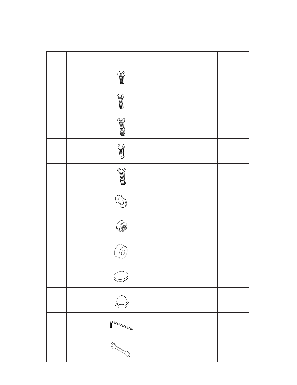
Part Picture Description Quantity
M Bolt(M6 X 15) 12
N Bolt (M6 X 45) 16
O Bolt (M6 x 55) 8
P Bolt (M6 X 35) 12
Q Bolt (M6 X 70) 4
R Steel Washer 80
S Nut 28
T Plastic Washer 28
U Bolt Cap 52
V Nut Cap 28
W Inner Hexagon
Wrench
1
X Outer Hexagon
Wrench
1 (M6)
HARDWARE CONTENTS
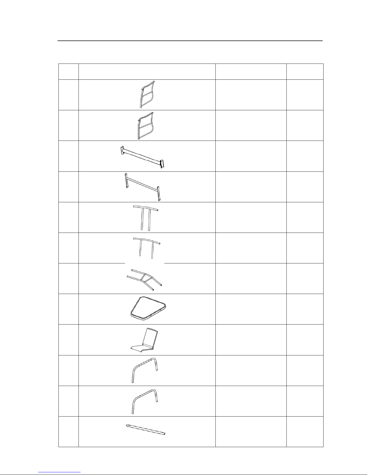
PACKAGE CONTENTS
Please lay out all parts prior to assembly or installation.
Read instructions prior to assembly or installation.
5
Part Picture Description Quantity
A Right Armrest 2
B Left Armrest 2
C Back Leg Connecting
Tube
2
D Swing Pole 4
E Table Top Support
Bracket (small)
1
F Table Top Support
Bracket (large)
1
G Left and Right Seat
Connecting Bracket
1
H Table Top 1
I Seat & Back 2
J Left Leg 2
K Right Leg 2
L
Upper Connecting
Tube of Left & Right
Leg
4
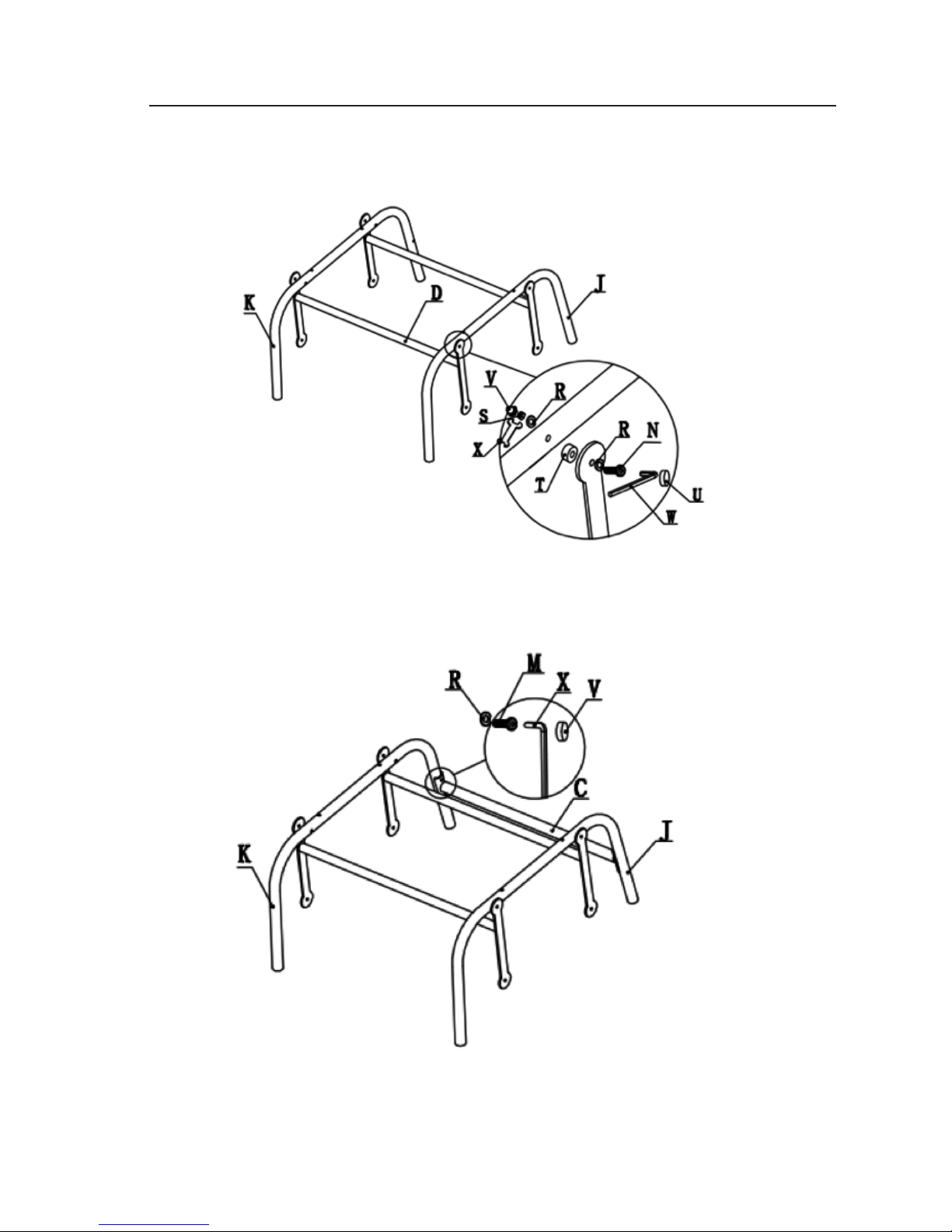
Step 1: Attach swing pole (D) to left leg (J) and right leg (K) with M6*45 Bolt (N), plastic washer
(T), steel washer (R) and M6 nut (S), as shown above. Do not overtighten the bolts.
Step 2: Attach back leg connecting tube (C) to left leg (J) and right leg (K) with M6*15 bolt (M),
steel washer (R) as shown above. Do not overtighten the bolts.
CAUTION: Do not use sharp equipment such as a knife and scissors when removing the
protective material, as it may damage the product..
* Place all glider parts and hardware on a soft & clean level surface.
ASSEMBLY INSTRUCTIONS
6
7
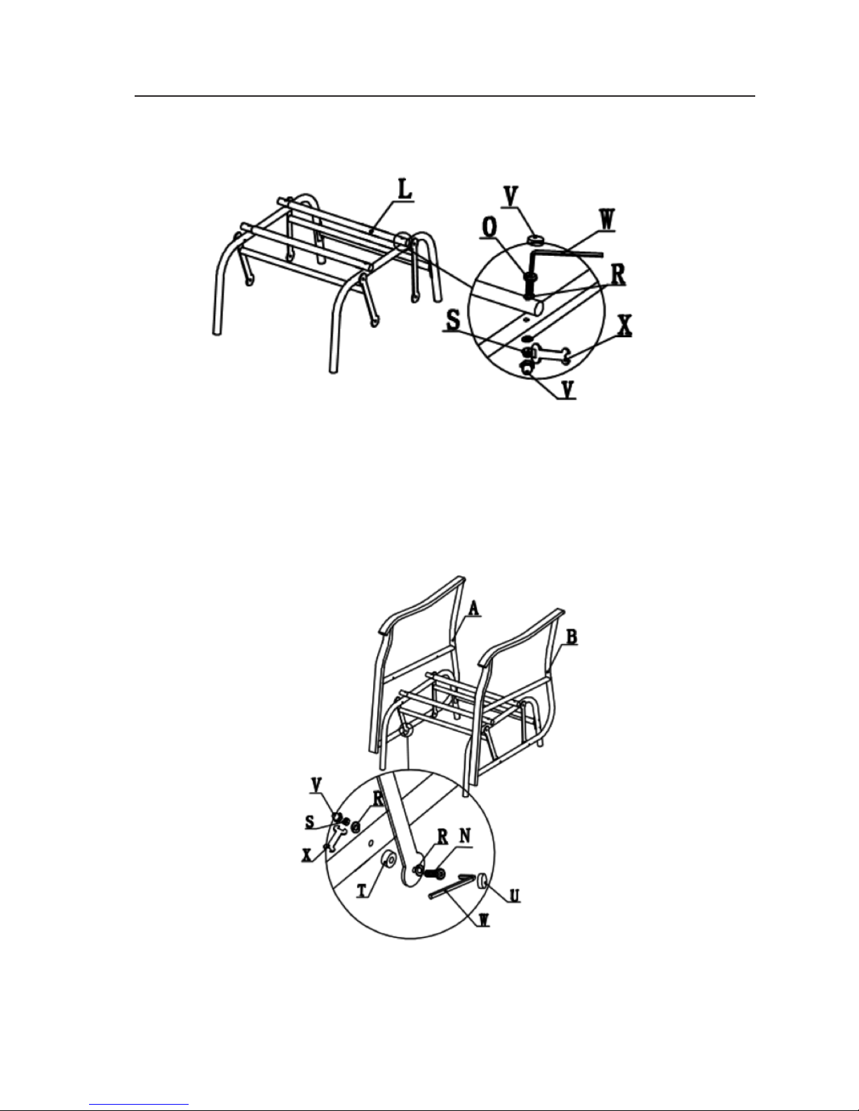
Step 3: Attach upper collecting tube (L) to left leg (J) and right leg (K) with M6*55 bolts (O), and
M6 nut (S) as shown above. Do not overtighten the bolts.
Step 4: Attach left armrest (B) and right armrest (A) to swing pole (D) with M6*45 bolt (N), Plastic
washer (T), steel washer (R) and M6 nut (S) as shown above. Do not tighten the bolts.
ASSEMBLY INSTRUCTIONS
* Repeat from step 1 to step 4 to assemble the other glider chair.
8
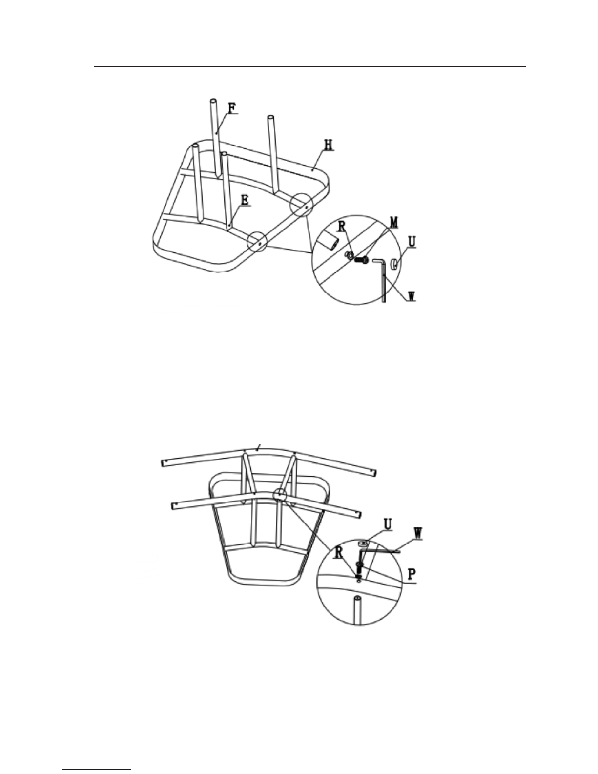
Step 5: Place table top (H) on a clean and soft level surface. Then attach table top support
brackets (small) (E) and table top support bracket (large) (F) to table top (H)with M6*15 bolt
(M) and steel washer (R) as shown above. Do not overtighten the bolts.
Step 6: Attach left and right seat connecting bracket (G) to table top support bracket (small)
(E) and table top support bracket (large) (F) with M6*35 bolt (P) and steel washer (R) as shown
above, do not overtighten bolts.
ASSEMBLY INSTRUCTIONS

Step 7: Turn the table over, Insert left and right seat connecting brackets (G) into upper
connecting tube of left & right leg (L). Attach it with M6*55 bolt (O), steel washer (R), and M6
nuts (S) as shown above. Do not overtighten the bolts.
Step 8: Repeat step 7 to attach other side of the table to glider chair as shown above.
9
ASSEMBLY INSTRUCTIONS

Step 9: Attach back (I) to left (B) & right armrest (A) with M6*70 bolt (Q), pplastic pad (T),
steel washer (R), M6 nuts (S) as shown above, do not tighten the bolts too much. Then attach
seat (I) to left (B) & right armrest (A) with M6 X35 bolt (P) and steel washer (R) as shown
above. Do not overtighten the bolts.
Note: There is only one connecting point between armrest and the back of chair, there are
2 connecting points between seat panel and armrest, as shown above.
Step 10: Check connecting points, and adjust if necessary, then, tighten all the bolts and nuts,
finnally, cover with bolt cap (U) and nut cap (V). The glider is ready to use as shown, above.
ASSEMBLY INSTRUCTIONS
10 11

90 DAY WARRANTY
This product is covered under a manufacturer’s 90 day warranty from date of purchase
against defects in materials and workmanship. This warranty does not cover damage due
to neglect, abuse or weather related damage. For full warranty disclosure, email us at
customerservice@atleisure.com, call toll free at 1-855-880-7205 or send mail to
1040 Boulevard SE Ste. B, Atlanta GA 30312.
WARRANTY
NOT COVERED UNDER WARRANTY
This Warranty excludes the following: general frame rusting; glass breakage; acts of
(i.e. wind, fire, or freeze); damage caused by improper assembly, caused by improper
assembly, accident, disaster, misuse, abuse, negligence and commercial use;
discoloration or fading of the finish or fabric as a result of exposure to the elements.
HOW TO FILE A CLAIM
If you are within your warranty you must have your receipt and pictures of your information
to send to ATLeisure at customerservice@atleisure.com, or send by mail to 1040 Boulevard
SE Ste. B, Atlanta GA 30312. This warranty gives you specific legal rights, and you may also
have other rights which vary from state to state.

For additional product information, please contact our
Customer Service Center at 1-855-880-7205 between
8am- 5pm Eastern Time, Monday through Friday.
2015 Distributed by Menard, Inc., Eau Claire, WI 54703
MADE IN CHINA
 Loading...