

Page 1
B
ACKFIRE
F5F
Petr Janku
Hermanice 72
Nova Paka
50901
BackfireF5F Page 1
Page 2
Fuselage
1 pc
Wing
1 pc
V-tail 1 pc
Connector
MPX
2 pc
Barrier motor
1 pc
Wing horn
4 pc
Screw for wing
2 pc
Barrier into fuselage for servos
1 pc
Wires
for servo
4 pc
Brass wires 2mm
4 pc
Ball pivots
– servo
2 pc
pc
pc
pc
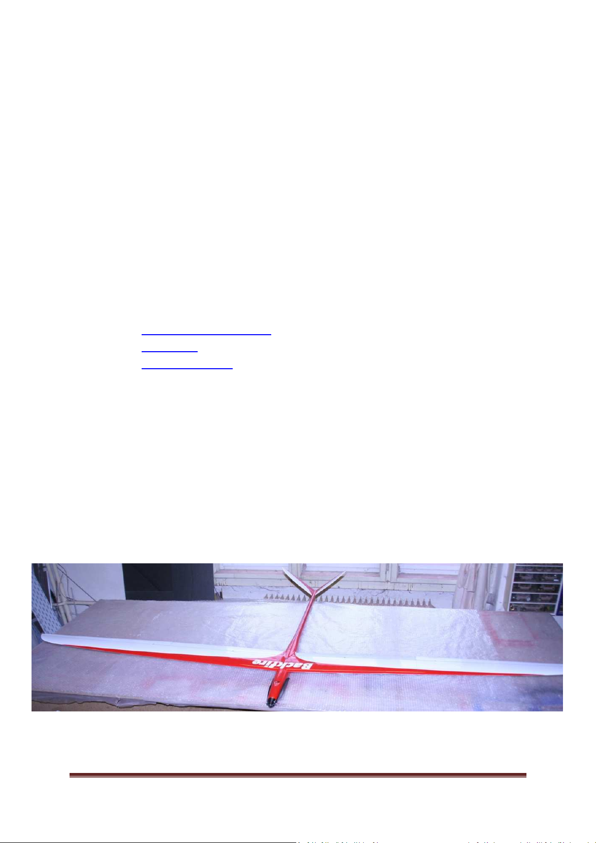
Thank You for buying the model of Backfire F5F. Backfire F5F is a full-carbonic model, it is
made by lamination into negative forms. Backfire F5F is suitable for the competitive league
F5F1, F5B/7, and for the hobby flying as well. The model was designed for competitive flying
and its design results from the latest innovation of the F5F category. The aerodynamic was
created by the German expert Dirk Pflug.
The fuselage is full-carbonic and there is a possibility to make an Aramid or a glass
fuselage as well, if the customer requests that. The wing is also full-carbonic and there is a
carbon cloth 93g/m2 with an orientation of ±45° on its surface, which inhibits from wingtwisting. The spar is made of UMS roving. The standard wing is made of one part, but there
is a possibility to produce the three-part2 wing according to customer´s wish. The elevator is
made of glass with a carbon flap of the cloth 93g/m2.
There is also a possibility to produce a model – version „Show“ for an extreme flying. Be
very cautious while flying with „Show“, because it allows to reach high flying-speeds you
should avoid the situation when you could damage someone´s assets or hurt someone.
1 Model
1.1 The Kit´s content
Ball pivots – V-tail 2
Threaded rod 2mm 4
Carbonic rod 700mm 2
1
It is necessary to use solid (one part) wing.
2
The three-part wing is designed for the hobby (recreational)-flying. It is necessary to take into account,
that this wing does not reach the strenght of the one-part wing.
BackfireF5F Page 2
Page 3
Crapping strips 4
pc
The cone
– diameter 38mm
Second glue
– medium
Activator for the second glue
The epoxide R+G L
-
285
The consolidator R+G 285
Micro
-
ballons + Aerosil
Utility knife
Transparent cellotape which does not leave a glue behind
Soldering
unit
Turn
-
bench Dremel
Servoconnectors
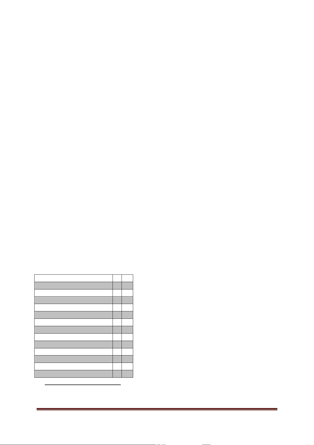
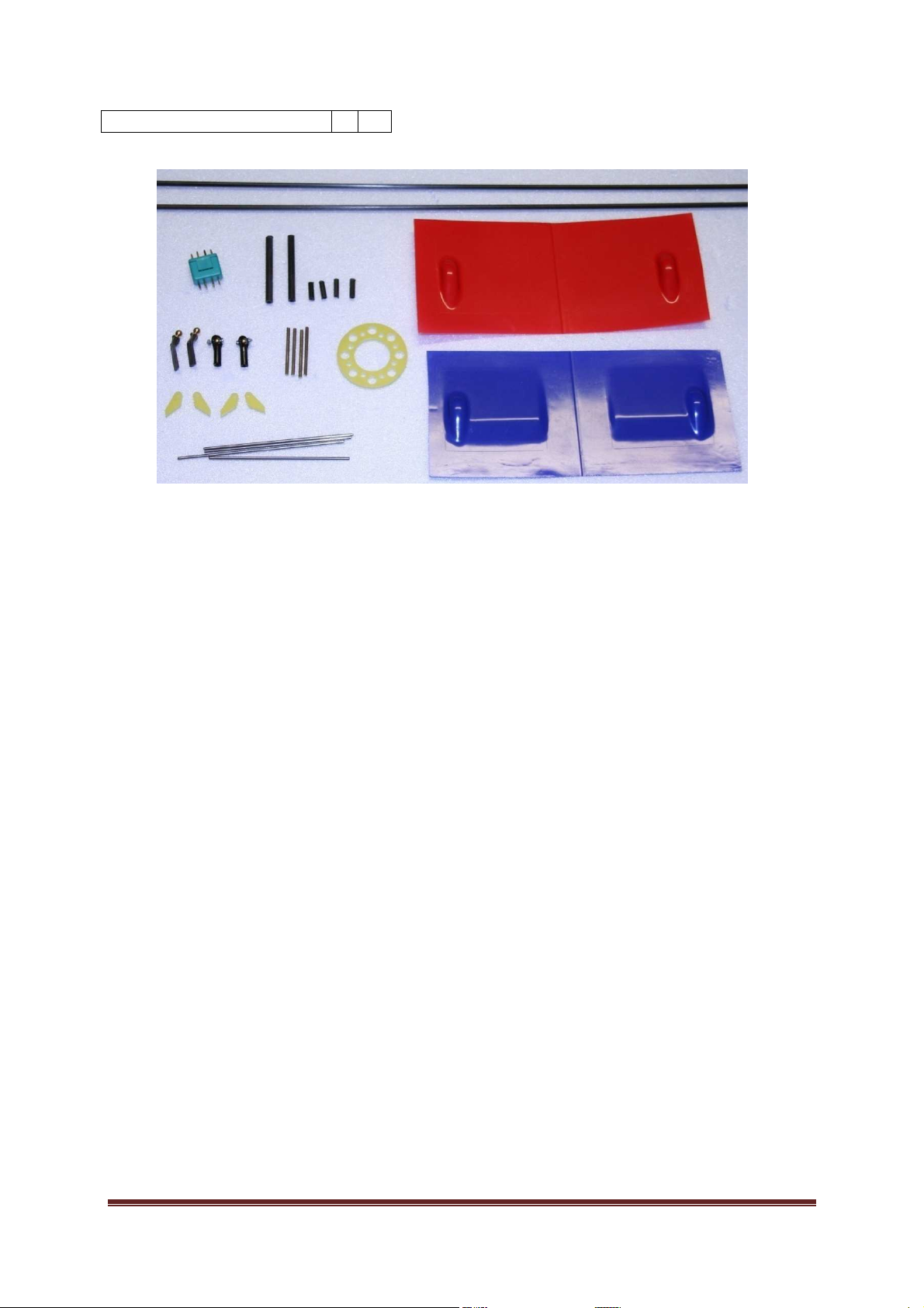
Picture 1: Accessories
1.2 The fittings needed for completing
BackfireF5F Page 3
Page 4

1.3 Recommended components
Hacker
B50 F5B
B40 F5F
Kontronik
Fun 500
Kira 600
Neu Motors
1509 F5F
1512
Plettenberg
HP 220/30/A1 P6 5:1
HP 220/25/A1 P6 7:1
3s Kokam 4000 EHD
4000
mAh
30C 147x43x29mm
3s Wide Energy WE 5000 SHD
5000
mAh
30C 157x43x27mm
3s Wide Energy WE 4100 SHD
4100
mAh
30C 157x43x30mm
3s Hi model 4600
4600
mAh
25C 165x48x24mm
3
3s TopFuel Hacker
5000
mAh
30C 155x43x29mm
4s4
Desire Power
4500
mAh
33C 165x44x35mm
5
4s Neu4100EP
4100
mAh
30C 160x45x31mm
4s Neu4900Xp
4900
mAh
25C 165x44x34mm
4s Hi model 3200
3200
mAh
25C 139x45x28mm
5s Hi model 3200
3200
mAh
25C 139x45x36mm
6
5s FlightPower Hacker
3200
mAh
20C 144x45x32mm
Ailerons
Hitec HS
-
125 Hitec HS
-
5125 MG
Volz Wing Max
Flasp
Hitec HS
-
125 Futaba S
-
3150
Volz Wing Max
V-tail Futaba S
-
3114
Futaba S
-
3154
1.3.1 Motors
It is possible to use any engine with the power from 200W to 2500W. The optimal engine
weight for competitive flying is c. 280g.
HP 220/30/A1 P6 7:1
1.3.2 Propeller
3S1P 17x18 with 7:1 gear
4S1P 16x16 with 7:1 gear
1.3.3 Batteries
HP 220/25/A1 P6 5:1
1.3.4 Servos
3
With 4/5s it is necessary to count with connecting the conductors directly at regulator (the conductors
cannot be drawn on the battery)
4
Practically it is possible to use any kind of battery with the maximum size of 170x45x35 mm
5
As long as the battery-high isn´t over 27mm, it is possible to use a battery up to 48 mm wide
6
This battery slightly pushes on the wing, if there is no need to use 5s battery, it is better to avoid it
BackfireF5F Page 4
Page 5
1.3.5 Receiver batteries
Intellect
AAA-750 mAh
A-
1400 mAh
X Cell
AAA-1000mAh
GP A-1100 mAh
A-
1300mAh
2 Fuselage
2.1 Cooling hole
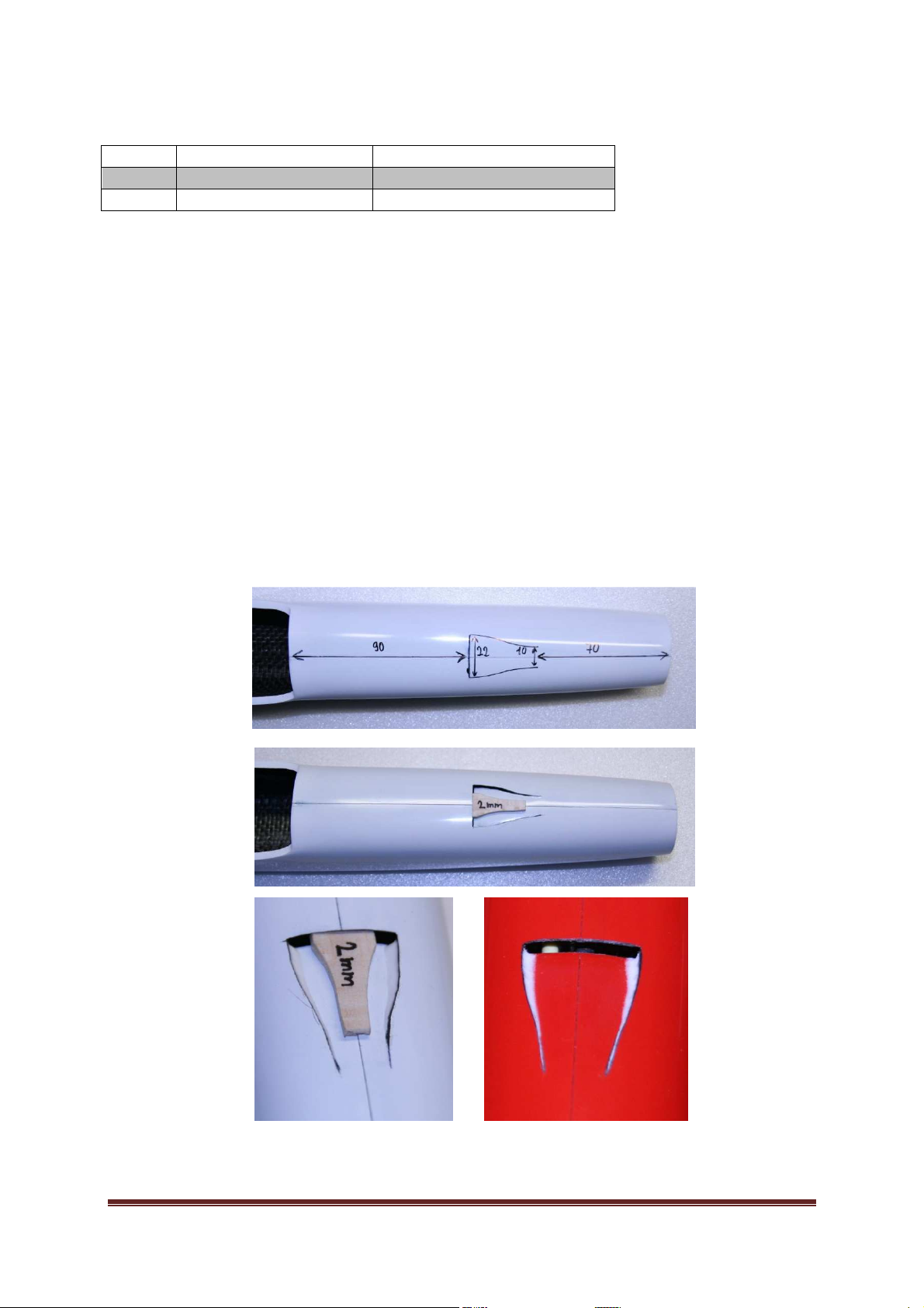
First we mark the place of the cooling air´s entrance with the felt tip and we cut through
the carbonic fuselage by using a knife. We press down the cut cooling entrance under the
fuselage level and we fix it with help of balsa – 2mm of thickness. We apply an epoxid with
microballons on the side rim of the cooling entrance and we leave the fuselage to hardend.
Picture 2: The cooling air´s entrance
BackfireF5F Page 5
Page 6

It is possible to make the cooling air´s entrance in the wing with help of a carbonic tubule
with the 14 mm diameter. The place for leaks is marked on the wing.
BackfireF5F Page 6
Page 7
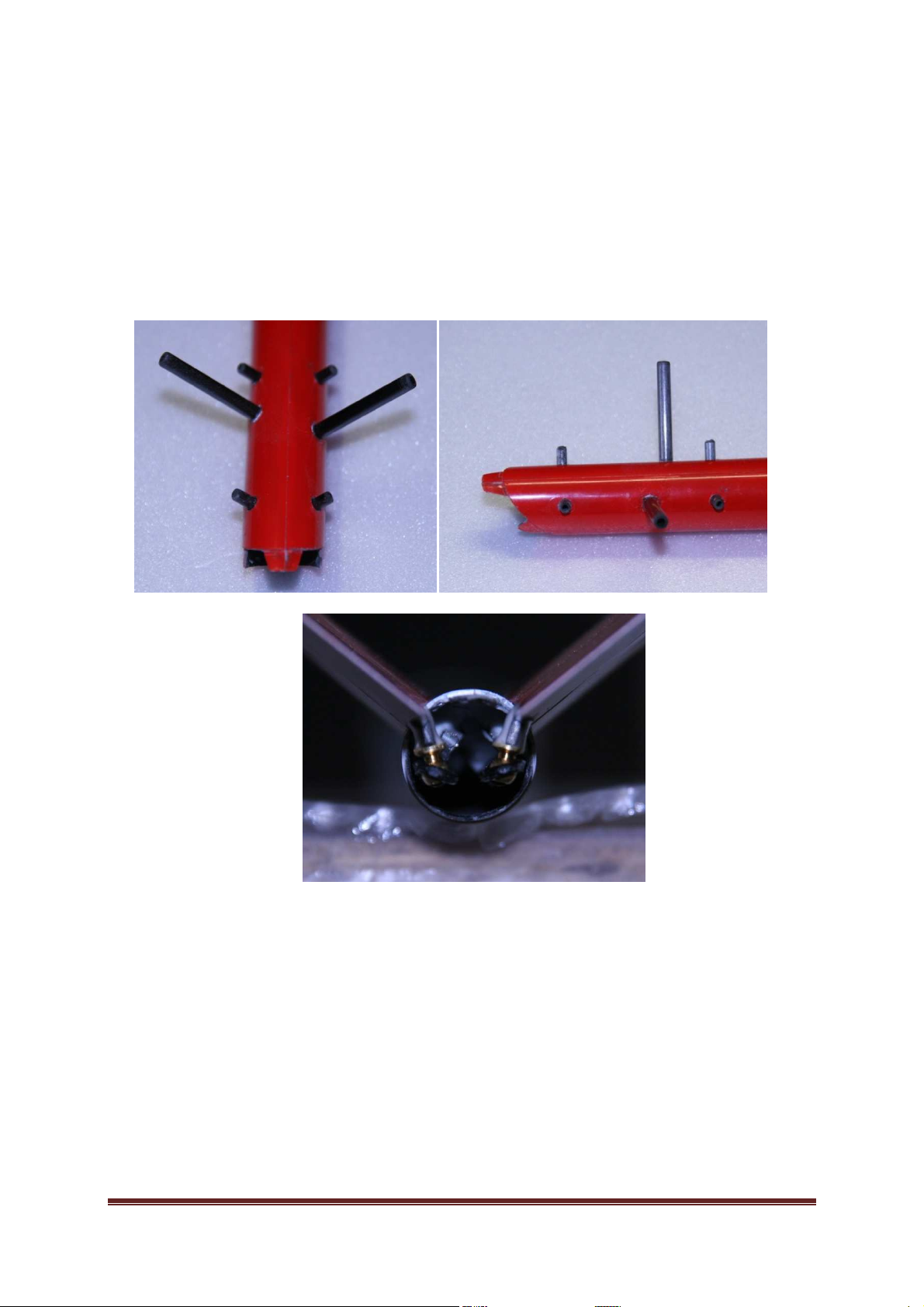
2.2 V-tail shoulder
The carbonic pins must be ground at their ends with help of a turn-bench and so their
edges are flicked off. Those pins that will be sticked up in the fuselage must be roughened,
so the pins will hold to fuselage well. We glue everything with the epoxide. Next we cut
throught the holes for the butterfly-lever. The hole is marked directly on the fuselage. We
glue the enclosed levers into the butterfly. The lever should be slipped into butterfly as
much as possible. We check the levers-position in fuselage after the glueing.
Picture 3: The soulder for V-tail
2.3 How to glue the butterfly´s servos
We shorten the carbonic pull at the lenght 645mm and 630mm. We grind their ends again
and flick off the edges. We flick off the edges of threaded rods M2 too. We glue the
threaded rods M2 into both sides of carbonic pulls in the way so that approximately 10mm
of the carbonic pulls sticks out the carbonic pipe. We screw the boll cups at one side.
BackfireF5F Page 7
Page 8
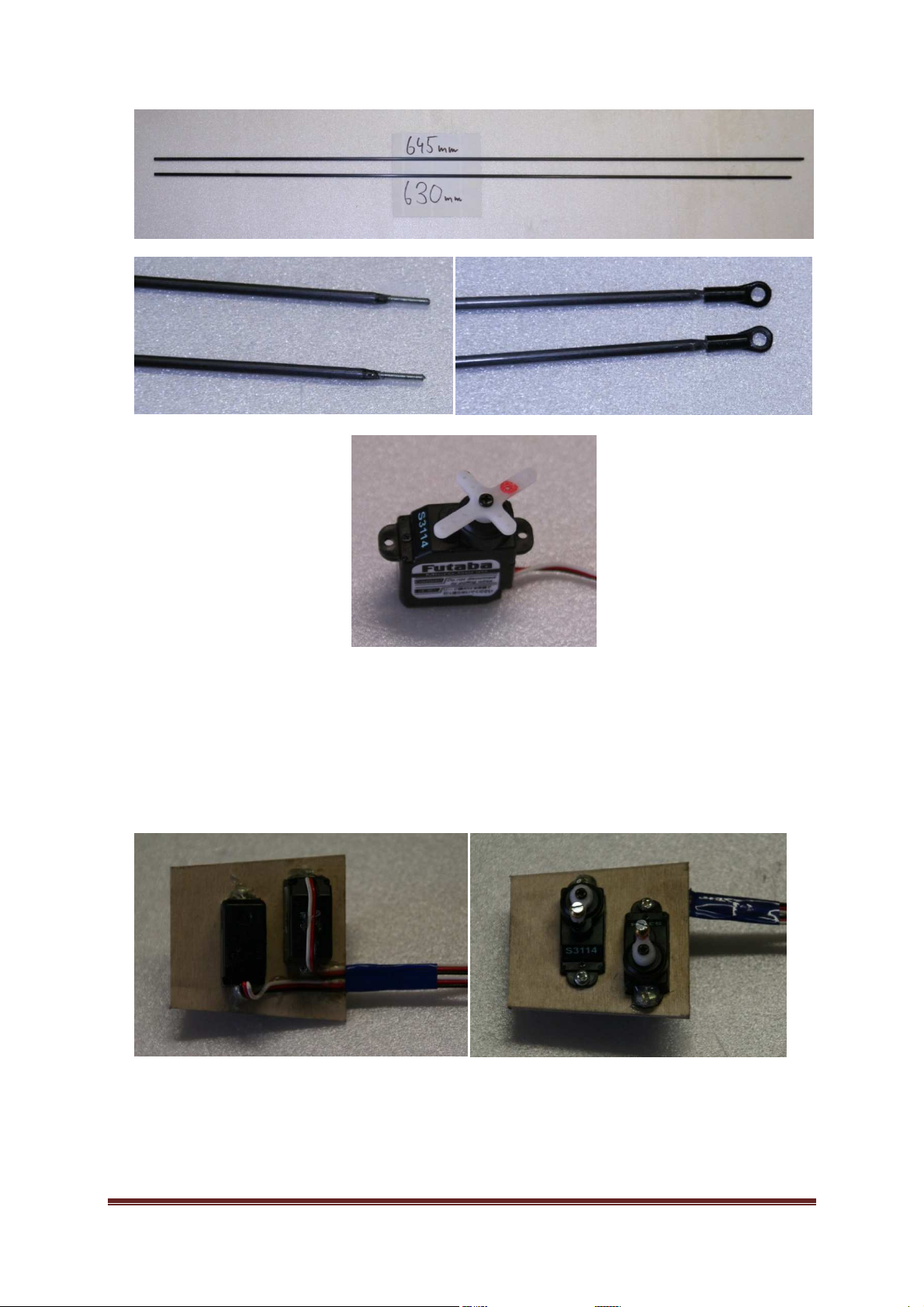
Obr. 4: The carbonics pulls for V-tail
We screw the servos into prepared barrier and we glue their bolts with the fusing gun so
that we could unloose the bolts in case we suffuse them by the epoxide. We secure the
servos cables in the same way.
Picture 5: The barrier for the butterfly´s servos
BackfireF5F Page 8
Page 9
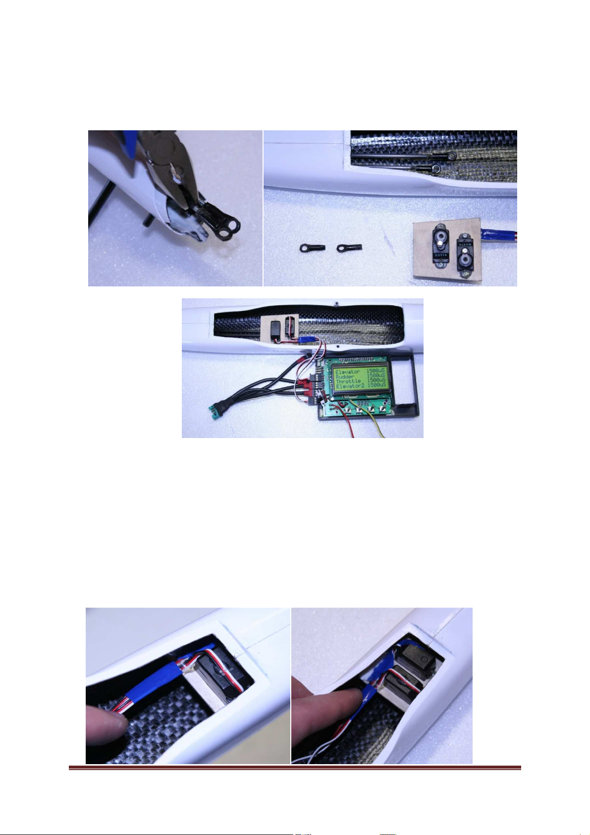
We give the barrier into the fuselage and set the servos´ neutrals. At the end of fuselage
we screw the next boll cups. It is absolutely necessary that the pulls are put through the
guide tubule in the middle of the fuselage!!!
Picture 6: Putting in the servos and setting up the neutrals
We apply the epoxide with microballons thickened by aerosil on the barrier in the way
that the mixture do not slump. We inset the barrier into the fuselage inchmeal and turn the
fuselage upside-down. On the other side we set the ball pivot of butterfly in the cup on the
carbonic pull. The butterfly-flap must be secured against the movement with help of
cellotape.
BackfireF5F Page 9
Page 10
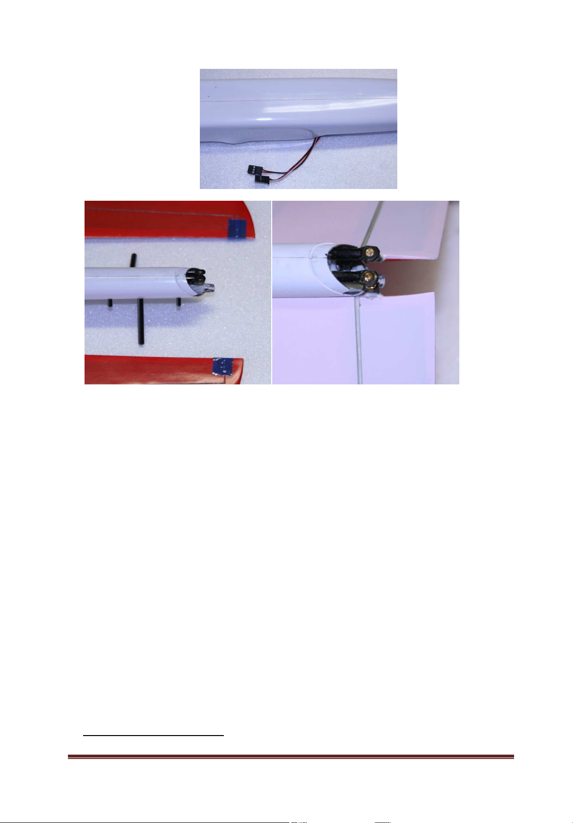
Picture 7: Glueing V-tail servos
Next we can put two balsa-battens7 with 1mm thickness between ball pivots on the servo
and the fuselage-bottom. The battens ensure the space needed for ball pivots movement.
We check the quality of glued joint. It is necessary to fix the butterfly to the fuselage before
the test flying. The best way is to stick the butterfly with epoxide glue.
7
if it is obvious that the gap is bigger than 2mm it is not necessary to put in those balsa-battens
BackfireF5F Page 10
Page 11
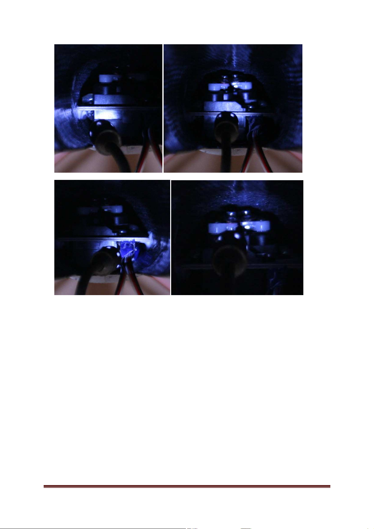
Picture 8: Control of the glued barrier
2.4 Motor Barrier
On circuit we make kerfs by using the saw or the milling machine. We screw the barrier to
the engine and protect the engine by using the cellotape against the possible epoxidepollution with. We apply the epoxide with ballons thickened by aerosil behind the edge of
the shoulder in the fuselage. We put the engine in the fuselage, we set the cone. We fix the
cone to the fuselage with help of cellotape. We let to harden the fuselage in the vertical
position.
BackfireF5F Page 11
Page 12
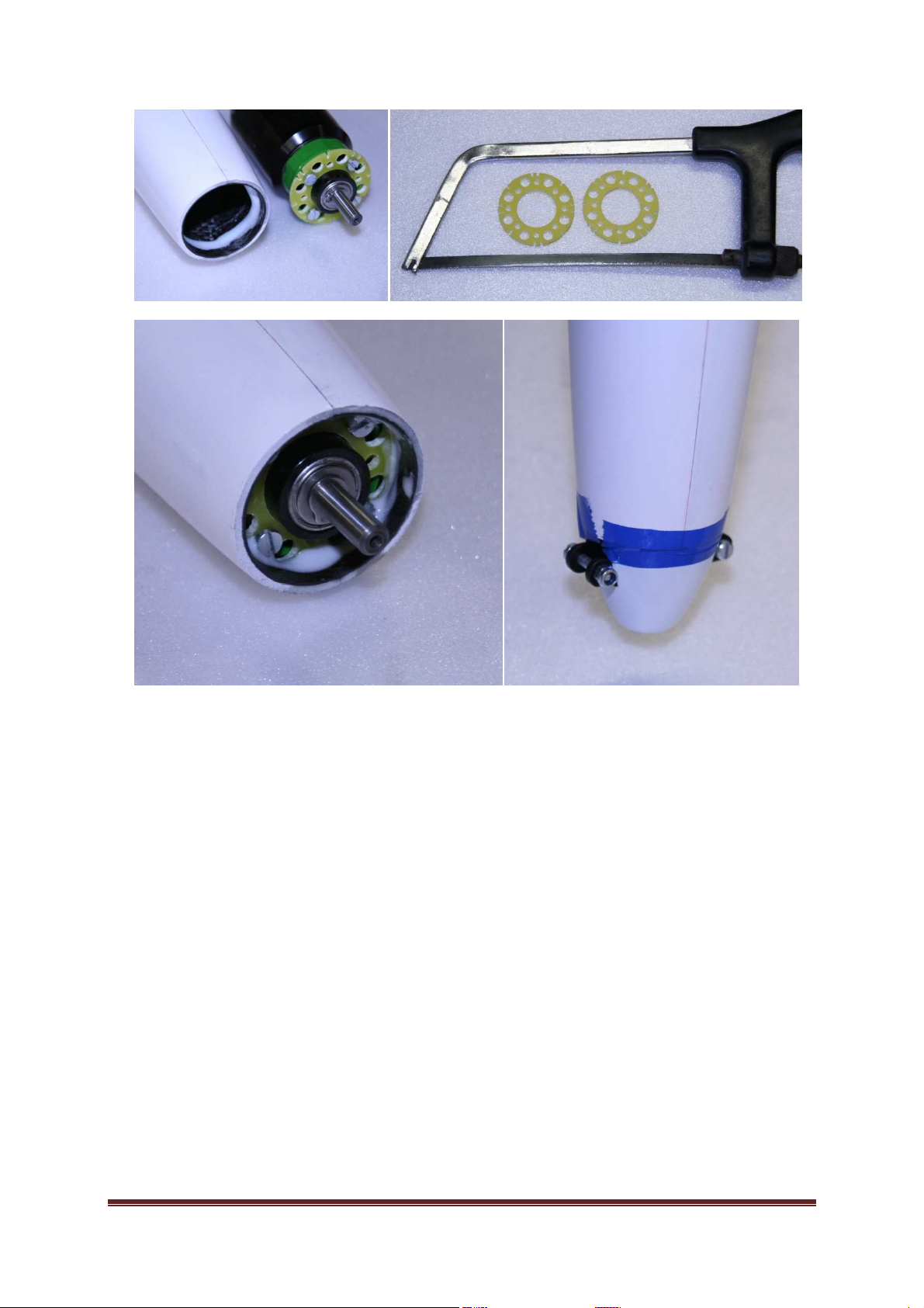
Picture 9: The glued-in of the engine-barrier
BackfireF5F Page 12
Page 13
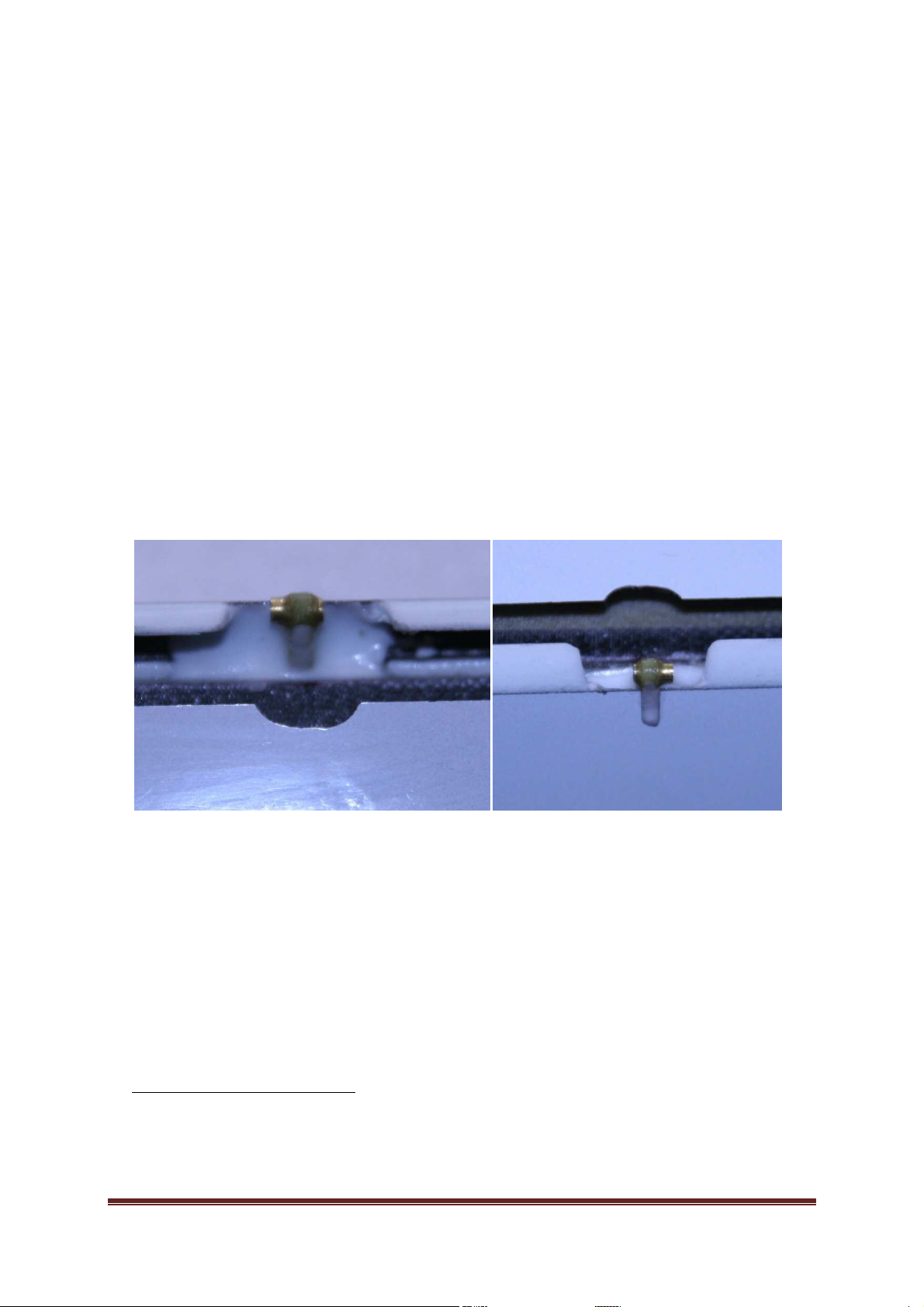
3 Wing
se with the diameter 2,5/1,52mm
3.1 Horns and Pulls
We glue the levers8 belonging in the flap in the distance of 7,3mm from the axis of
rotation and the levers for wings in the distance of 4,4mm from the axis of rotation. The
lever of the flap´s servo will have the hole in the distance of 7,3mm9 from the axis of
rotation and the lever of the butterfly´s servo in the distance of 3,0mm10. The pull for the
flap is 38mm long and for the wing 29mm. The pull is made of steel wire with the diameter
1,5mm and of brass lumber with the diameter 2mm. We cut c. 2mm of thread in the brass
lumber and we bend the lumber in the shape of the letter L and we finish the thread. The
thread should be c. 5mm long. We bend the steel wire only and the length of the bend
should be c. 5mm too. We roughen the places which we are going to solder by using an
emery paper. In the lever of the flap´s servo we cut the M2-thread and we glue up the
female screws. It is necessary to grid down the servo shaft by the lever of flap.
8
I recommend to complement the levers with the brass ca
and the length 4mm
9
when the lever of the servo and the flap have the same distance, then by the servo-deflection of 90° the
flap-deflection is 90° too
10
when we use this proportion, the wing-deflection is c. 8mm by up motion and c. 6mm by down motion
BackfireF5F Page 13
Page 14
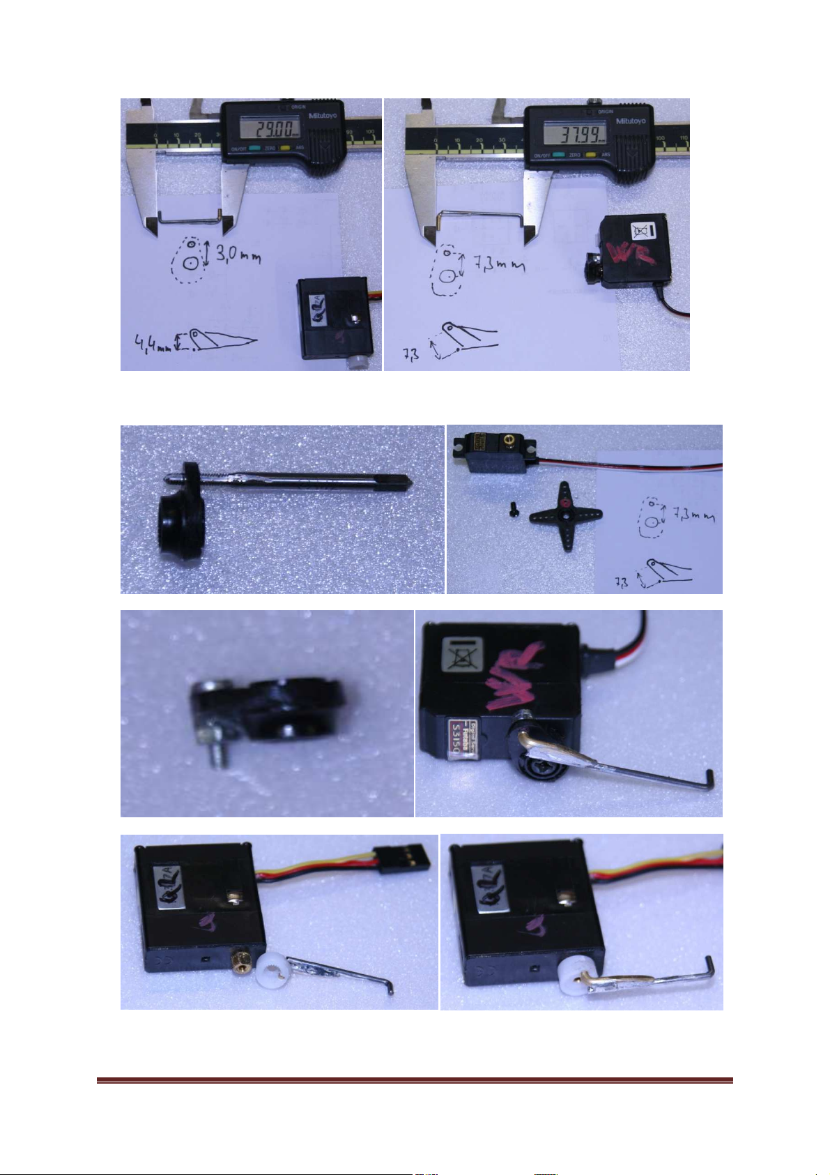
Picture 10: Levers and pulls of the wing
BackfireF5F Page 14
Page 15
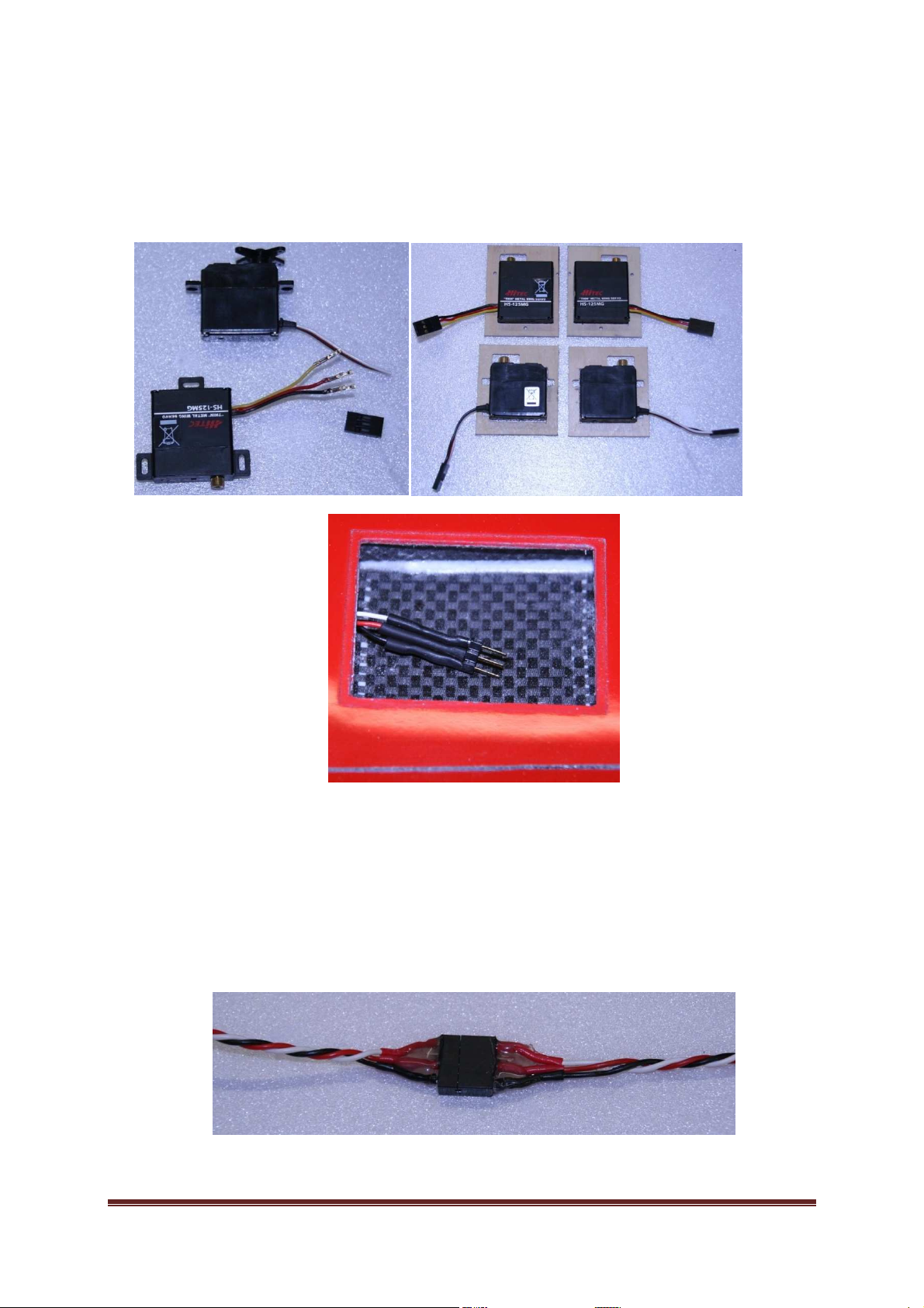
3.2 Cabels of servos and servoholder
We shorten the servos´cabels up to 4cm of distance. We solder the pins from the crushing
bar on the servos´cabels pulled through the wing. Or we can crimpen the original pins from
the servo-connector. We prepare the septa from plywood 1,5mm for each servo.
Picture 11: The cables of servos and septa of servos
3.3 Connectors Wing/Fuselage
In case we work with the three-piece wing, we have to solder the connectors into wings
first and then we glue up them with an epoxide glue. After this the next work procedure is
the same like working with the one-piece wing.
Picture 12: The connector for aileron of three-piece wing
BackfireF5F Page 15
Page 16
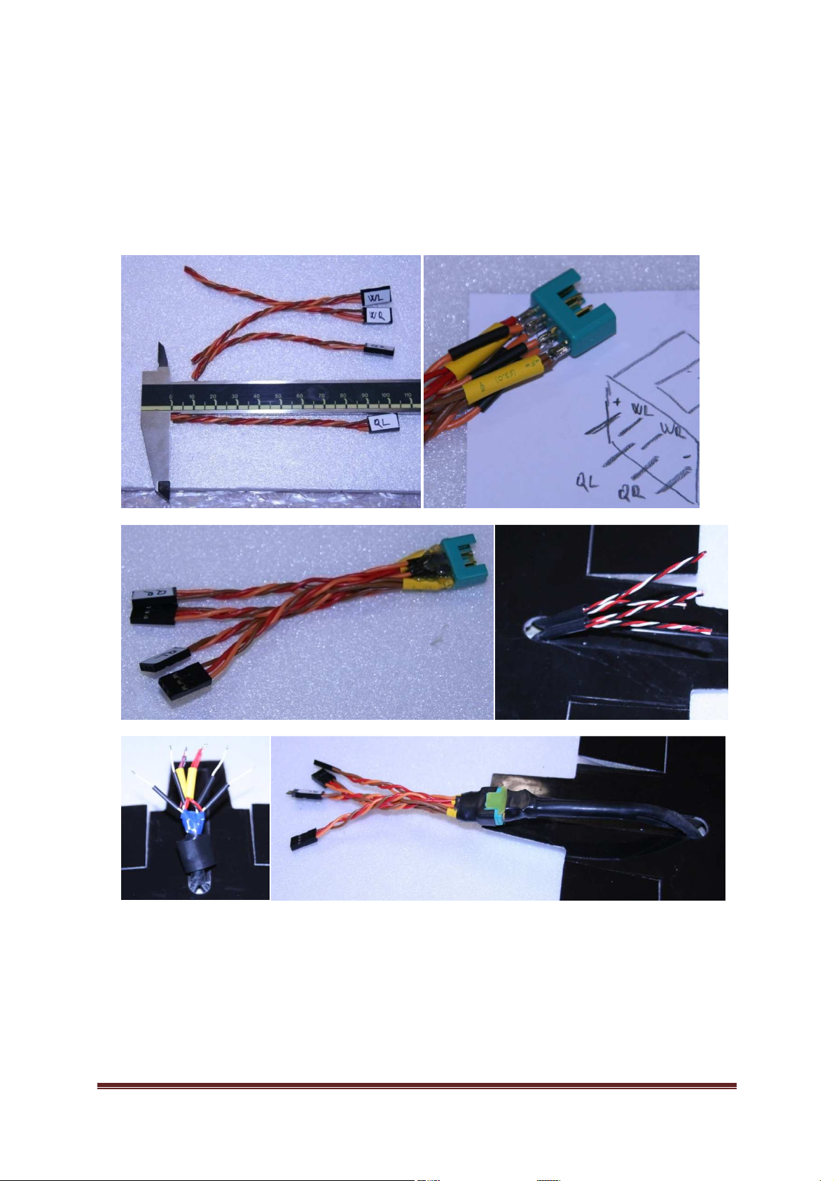
The length of cables to the receiver should be c. 9cm. We strip cables, tin-plate them and
we put the shrink- spaghetti insulation on them. We solder cables to the connector MPX,
strip the isolation with the hot-air gun and fix all with the fusing gun. We use the same work
procedure while soldering the connector MPX in the wing. We let the cabels so long that
their distance from the end of the wing is c. 3cm. And, beside the shrink- spaghetti
insulation, we pull on the silicone insulation on the cable too.
Picture 13: Connectors – wing/fuselage
BackfireF5F Page 16
Page 17
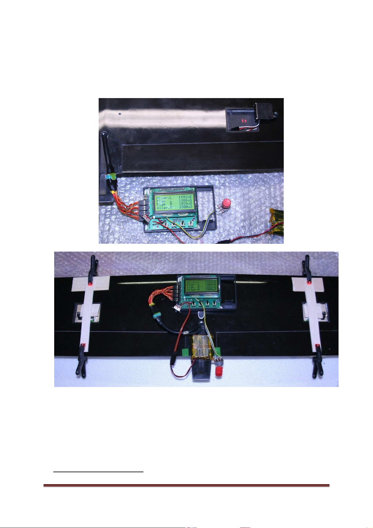
3.4 Sticking up the servos into wing
First we set the neutrals11 to all servos. We stick up the servos into wings with an epoxide.
We ensure the ailerons and flaps to the wing in zero deflection by using a cellotape and we
set the neutrals of all servos again.
11
The neutrals of the ailerons are c. 1500 μs and of the flapt c. 2000 μs and 1000 μs !!! Important!!!
BackfireF5F Page 17
Page 18
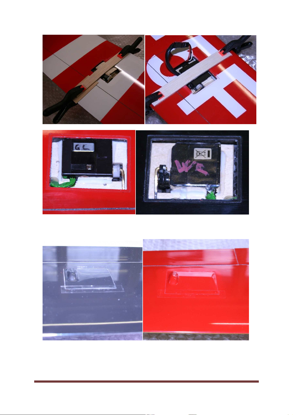
Picture 14: Sticking the servos into wing
Picture 15: The servos´caps
BackfireF5F Page 18
Page 19
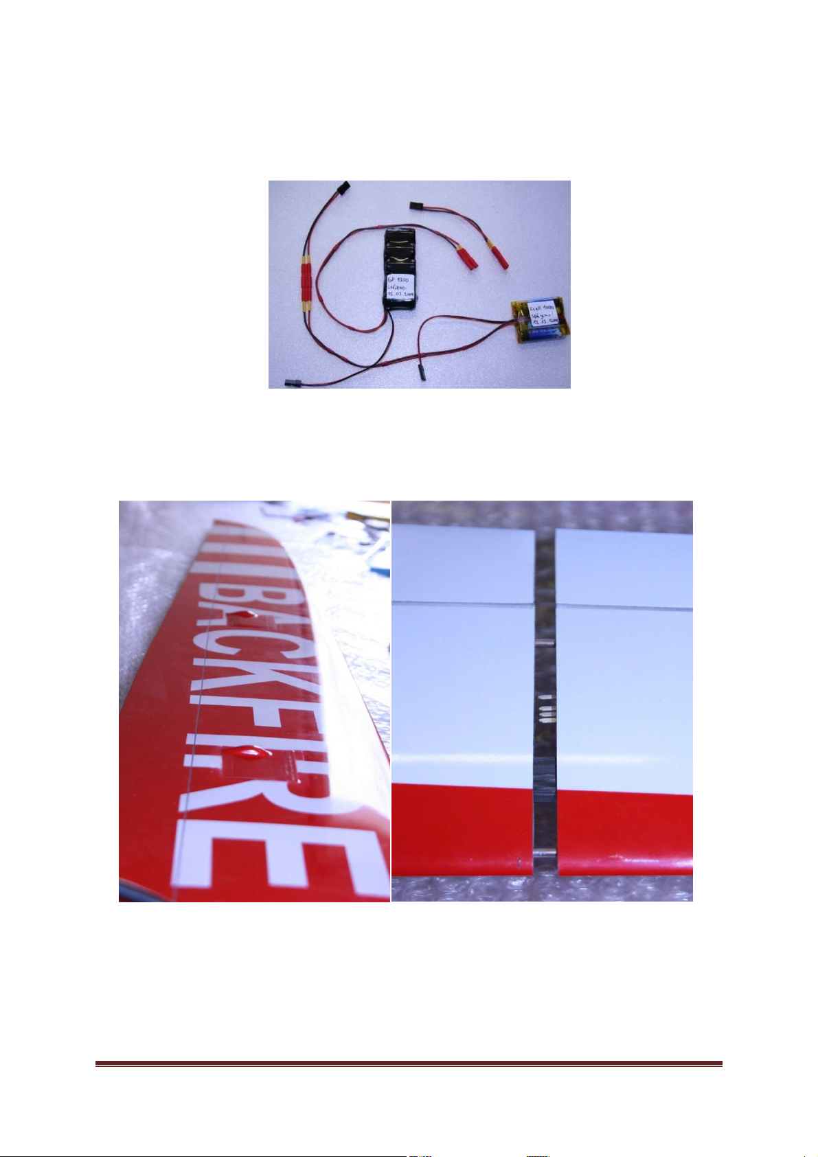
It is necessary to use the external voltage supply for power supply. It is more reliable to
use the connector 2mm instead of switch. The connector 2mm has a better contact. The
conductors to the battery have the cross section 0,5mm
2
.
Picture 16: Voltage supplies for the deck equipment
4 Others picture
BackfireF5F Page 19
Page 20
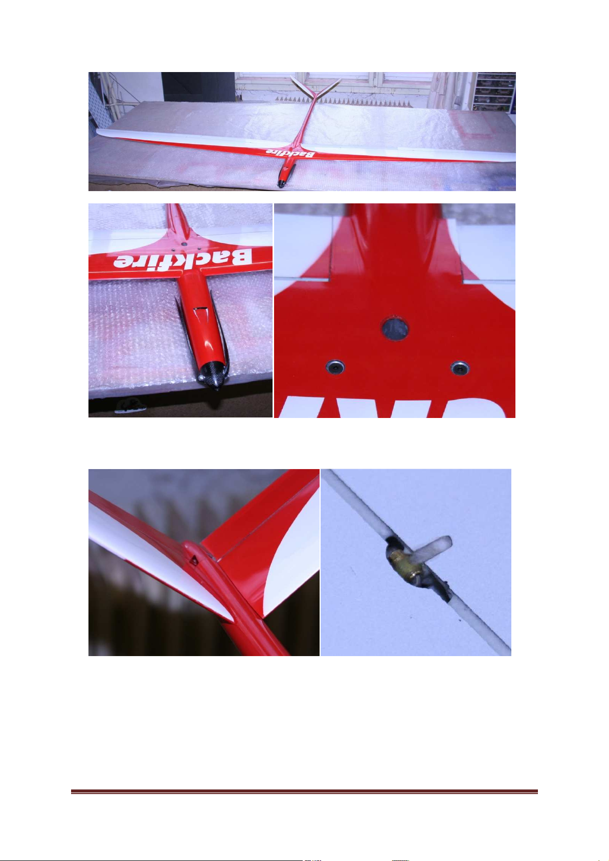
Picture 17: Input and output of the cooling air
BackfireF5F Page 20
Page 21
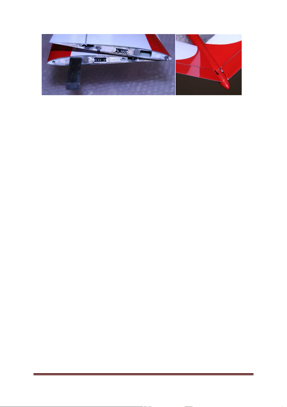
Picture 18: The tail piece of the fuselage, the divided wing
5 Deck Equipment
We place the receive batteries tight behind the engine with help of nails Dual-lock. We
place the receiver in front of butterfly´s servos. We hold the regulator also with nails Duallock on the top of the front part of fuselage. I recommend to use 2mm power connectors fot
the deck equipment instead of switch. It is possible to ensure the driving batteries against
movement with help of nails Dual-lock as well. We choose the fixing of the battery to the
bottom of fuselage according to the high of the driving battery, or we place the Dual-lock on
the bottom of the wing and the top of the battery.
BackfireF5F Page 21
Page 22
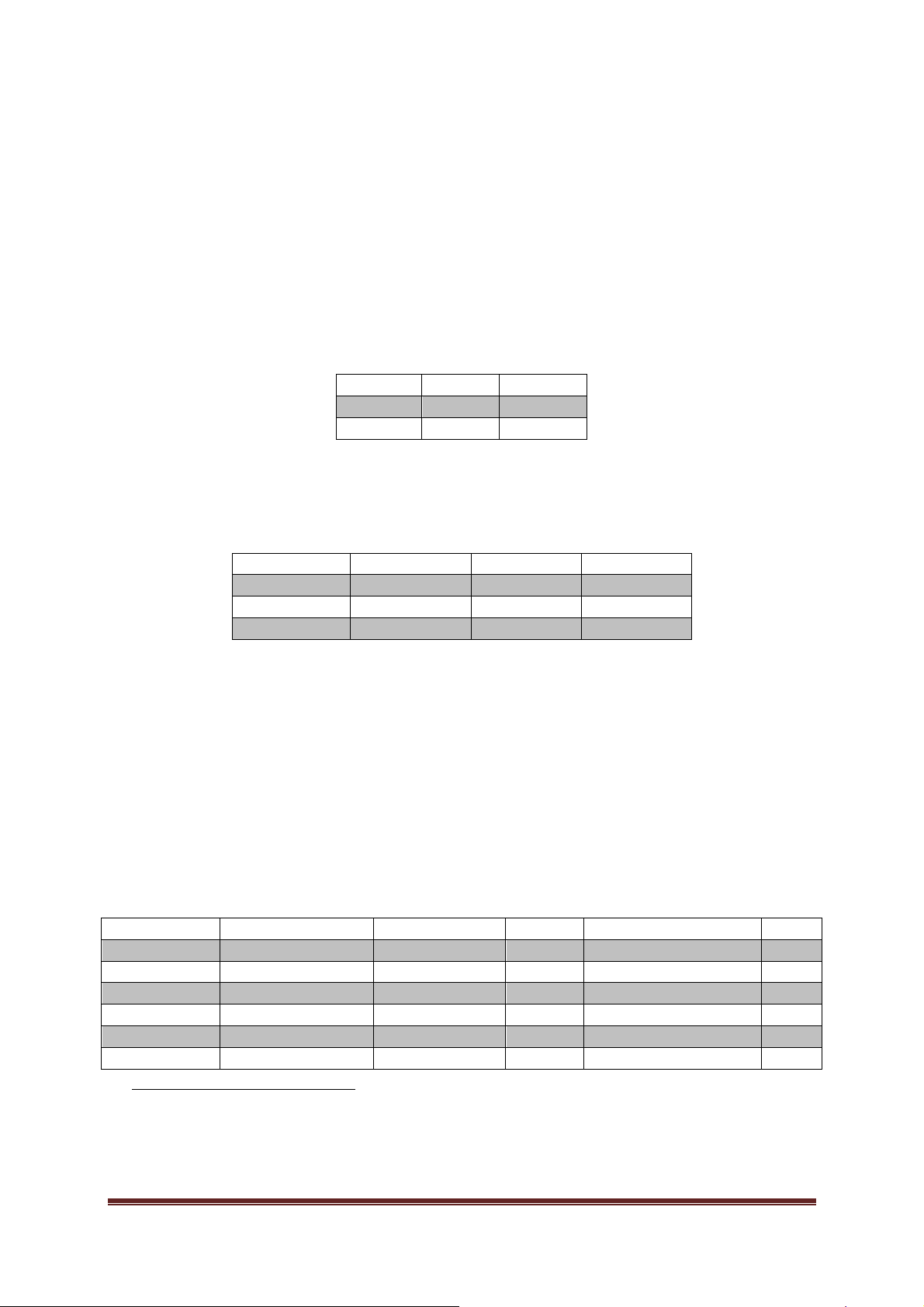
6 Setting of deflections, adjustment of phases and
V-tail -
4mm
12
+4mm
Ailerons
-6mm
+4mm
Flaps
-1mm
+80˚
Function
Flaps
Ailerons
V-
tail
Speed
-0,5mm
-0,5mm
-0,3mm
T
hermik
+5mm
+3mm
-0,5mm
Landing
+80
˚13 -3mm
+2mm
Model
Motor
Power batteries
Propeler
Regula
tor Rising
Rek
reation
SNeu 1509/1Y/6.7
4S 3700, 25C
16x16˝
Castle Creations 125
40m/s
Competetion
SNeu 1509/1D/6.7
3S 4500, 33C
17x18˝
Castle Creations 125
55m/s
Show
SNeu 1512/1D/6.7
4S 3700, 30C
17x18
Castle Creations 125
65m/s
Rekreation
Kira 500
-44-
6,7 4s
3200, 30C
15x16
Jive 100+LV
40m/s
Competetion
Kira 500
-50-
6,7 4S 3700, 30C
15x16
JazzFAI18/Jive 100+LV
55m/s
Show
Kira 600
-38-
6,7 4S 3700, 30C
16x17
JazzFAI18/Jive 100+LV
60m/s
centre of gravity
6.1 Setting of servos´ deflections
The adviced setting as an informative one. Every pilot has different deflections habits and
you can change this deflection after you get familiar with the model.
Table 1: Setting of servos´deflections
6.2 Adjustment of flying phases
Table 2: Adjustmens of phases
6.3 Gravity center
The basic adjustment of gravity centre is 56mm measured from entering edge. If you
move the gravity centre forward the model will be more stable. If you move the gravity
centre backward the model will better turn the basis turns.
7 The proofed gears
12
+ deflection is ment as a positive one, so it is a down-deflection, and – deflection is ment as a negative
one, so up-deflection
13
It is possible to heighten the flaps´deflection up to +90° when the undershooting is demand
BackfireF5F Page 22
Page 23
Rekreation
Hacker B50
-
9S+6,7
TopFuel 3800
-
3S
15x13
Master Basic 70
-SB
Competetion
Hacker B50
-
TopFuel 5000
-
17x18
Master 195
-O-
F5B 55m/s
Show
Hacker B50
-
5L+6,7
-
4S 3700, 30C
17x18
Master 195
-O-
F5B 65m/s
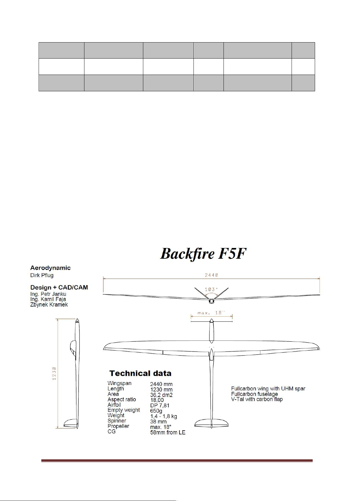
Wingspan
2440
mm
Lenght
1230
mm
Area
36,2 dm
2
Aspect ration
18
Airfoil
DP 7,81
Empty weight
1,4-1,8 kg
Spinner
38 mm
Propeller
18˝
CG 56 mm
from LE
5M+6,7-FAI
FAI
3S
8 Technical parameters
BackfireF5F Page 23
 Loading...