


Dynamis

Dynamis User Guide
2
Contents
Introduction 3
Hardware overview Handset 4
Command station 5
Handset screen overview 6
Action key icons 7
Getting Started 8
How to use the joystick 9
How to configure the locomotive roster 9
How to manage consists 13
How to operate turnouts and accessories 15
How to program locomotive decoder CVs 16
How to configure using the System menu 17
How to make the best of Dynamis on your layout 19
Safety and care of your Dynamis 21
Fault finding 22
Other Bachmann E-Z Command® DCC products 23
Warranty information 23
Technical support 23
Dynamis Menu Reference 24
Dynamis User Guide
3
model train control system. You have chosen an easy to use yet highly sophisticated
product. Please take a few moments to become familiar with the product by reading
Introduction
Thank you for your choice of the Bachmann E-Z Command® Dynamis® DCC
this manual before proceeding. Using the Dynamis DCC system is simple as all
actions are guided by the screen icons with four Action Keys beneath.
The Dynamis DCC system features a powerful bi-directional infrared hands- free
control unit for convenient operation around your layout. Information passes both
ways between Command Station and Handset to ensure communication integrity.
Both units have been designed to have a wide transmission and reception arc for
optimal performance.
Dynamis can be used with model trains of any scale: power hungry Large Scale
trains may require the use of the E-Z Command® 5-amp booster.
This Dynamis starter system contains:
Wireless handset
Command Station with receiver
Lanyard
Track lead
AAA / MN2400 /LR03 batteries (4) for handset
Mains transformer
IMPORTANT
Bachmann E-Z Command® Dynamis® runs NMRA DCC decoder fitted trains
only: it does not run a train without a decoder. Damage may result to any train
without a decoder placed on a track powered by Dynamis.
Dynamis is a DCC system which is compliant with the NMRA DCC standards
Dynamis User Guide
4
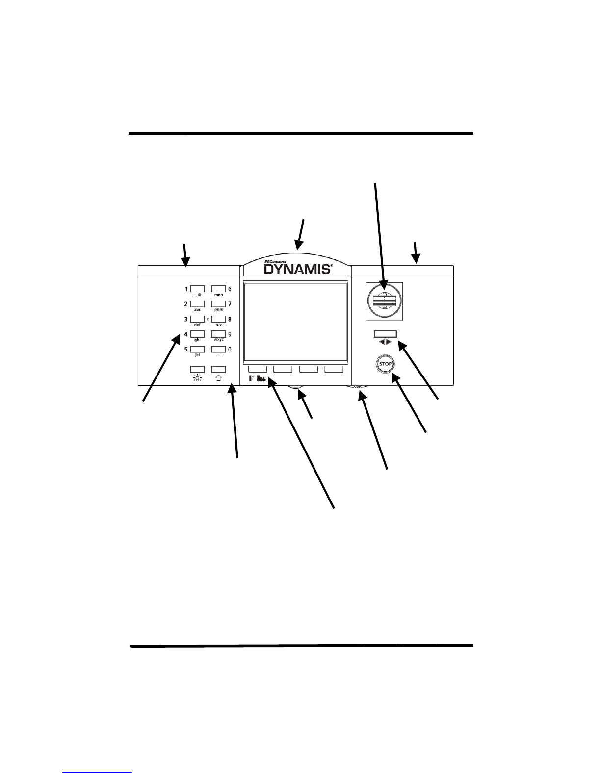
alpha numerical
Joystick
Hardware overview
The Handset
infra-red receiver / transmitter
Battery
compartment
Keypad for
direct control
of up to 21
functions,
accessory
hotkeys and
keypad for
loco and
accessory
address entry
Screen
Shift key to switch
between the function
keys operating F1 to
F10 and F11 to F20.
In accessory mode
sets function keys to
be accessory hotkeys
Battery
compartment
Lanyard fixing
Em
ergency stop
On / off switch
Action keys
Left hand is MODE key to switch
between locomotive and
accessory control
Direction
Dynamis User Guide
5
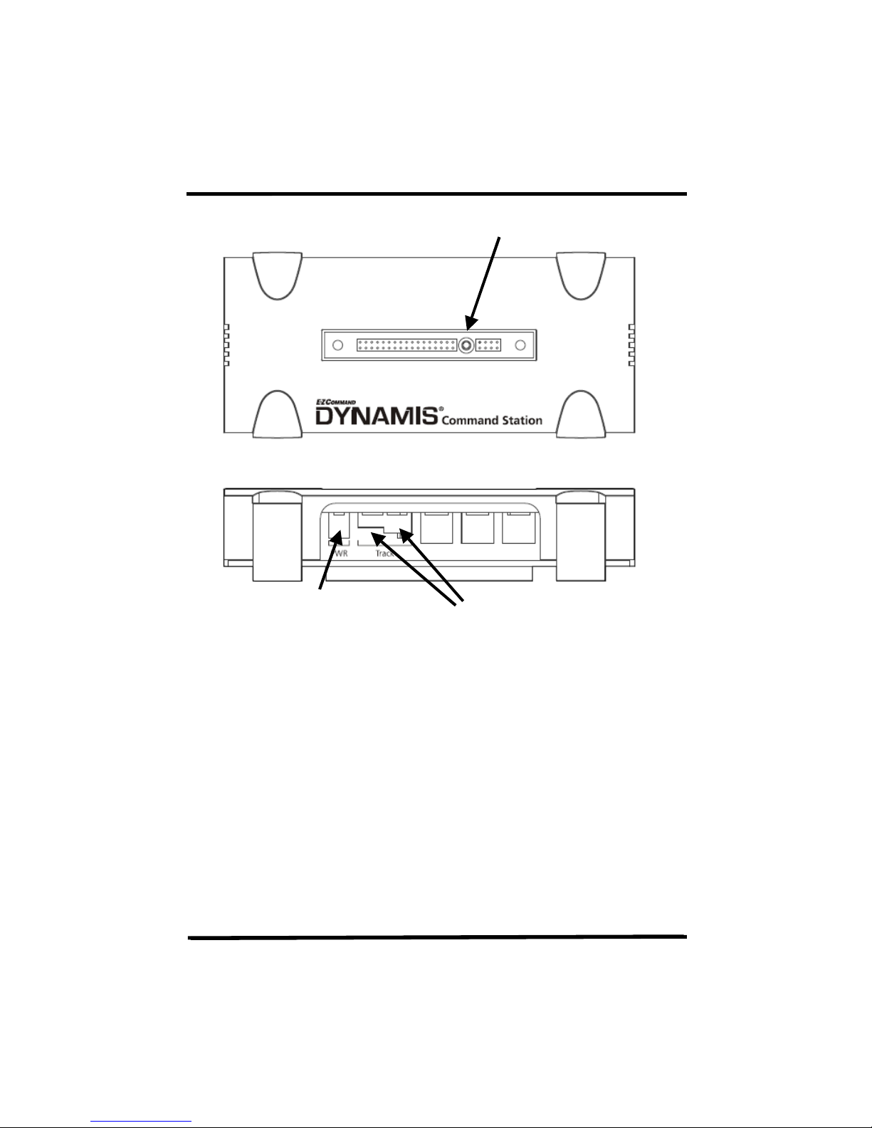
The Command Station
DC power pack connector
Use only the supplied wall
transformer
Receiver connection
Output connectors,
3.5mm jack or plug with screw
terminal
Receiver LEDs
There are indicator LEDs located within the receiver
NORMAL OPERATIONS
Left hand - constant indicating power to Command Station
Right hand - flashes on receipt of Handset signals
STOP pressed / short circuit on track
Left hand flashes
HANDSET OUT OF RANGE OF COMMAND STATION
Left hand and Right hand both flash rapidly
Dynamis User Guide
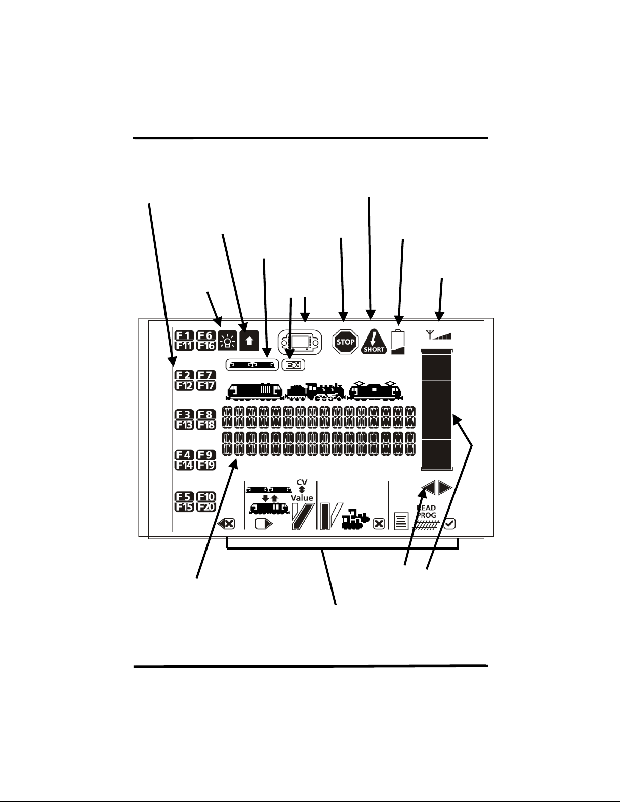
6
Used only when
the Dynamis Pro
Shift key pressed
Handset screen overview
Indicators for decoder function status
on/off
indicator
Consist
indicator
Headlights on
Box is also used
indicator
Track short circuit reported by Command
station
STOP
indicator
Low battery power
infra-red signal
condition
Text, including loco details and
menus etc
Speed and direction indicators
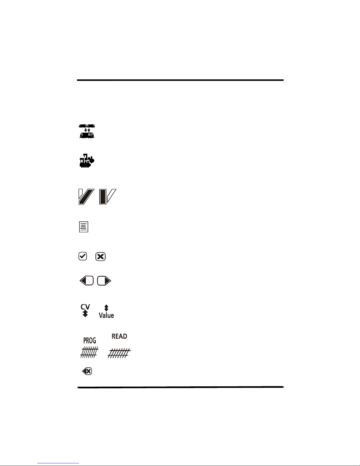
Action Key icons
Dynamis User Guide
7
[STRAIGHT]
Action key icons
Icon Key purpose when icon shown Referred to as
Add loco to / remove from Consist
Select locomotive by address
Turnout / accessory operation - turnouts
left / right or accessories on / off
Access the menu
Accept Cancel
Scroll left or right
[CONSIST]
[LOCO]
[DIVERGE]
or
[MENU]
[ACCEPT]
[CANCEL]
[SCROLL]
Move between CV selection and value for
CV in the programming menus
Write value to CV / read from CV
(reading CV values requires Dynamis ProBox
Backspace in text entry
)
[CV<>]
[<>VALUE]
[READ]
[PROG]
[BKSP]
Dynamis User Guide
8
. Turn on the Handset with the switch underneath – the Handset always powers up
Getting Started
1
. Attach lanyard to the handset. To avoid
dropping the unit use the lanyard around neck or
wrist.
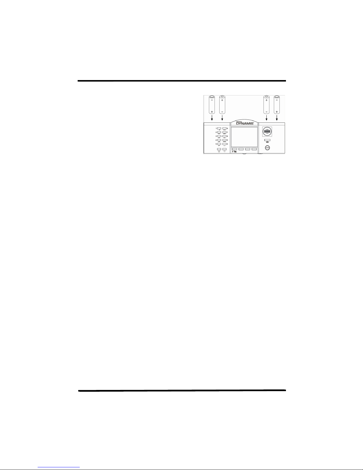
2
. Insert 4 AAA batteries into handset orientating
as shown on the diagram. The battery covers are
removed by carefully releasing the clips at the rear
of the handset
3
. Connect receiver to terminal on top of the Command Station.
4
. Place Command Station by layout, locating in a position with a good angle of view
to the Command Station infra-red receiver. Remove existing controllers / power
packs and connect the wires to the Command Station.
Use the red lead with jack plug to connect to Bachmann E-Z Track® or the
Bachmann Branchline track powerclip
Other leads with bare wire connectors can be connected to the green
connector block which plugs to the Command Station. This is
recommended for layouts using higher track power.
Please refer to ‘
5
place with a twist action. THIS PROCEDURE SHOULD BE CARRIED OUT BY AN
ADULT
6
into wall socket. The LED on the Command station receiver will be illuminated.
7
with the STOP cutout in place (press STOP button to proceed) and ready to run a
locomotive with address 3.
8
with an address of 3.
To run a locomotive with a different address, press [LOCO] key and then enter
locomotive address and press [ACCEPT]. This locomotive number shows on the
screen along with a default roster entry that has been created.
section for advice on connecting to existing layouts
. Select the appropriate mains pins for the wall transformer: they fit and lock in
. Connect the power supply lead to the Command Station. Plug the transformer
. Place a locomotive on the track. New DCC locomotives or decoders are shipped
How to make the best of Dynamis on your layout’
Dynamis User Guide
9
the locomotive to a stop. Change direction by pressing the direction button beneath
joystick or the [LOCO] key. Set the train running. Move back to the first train by
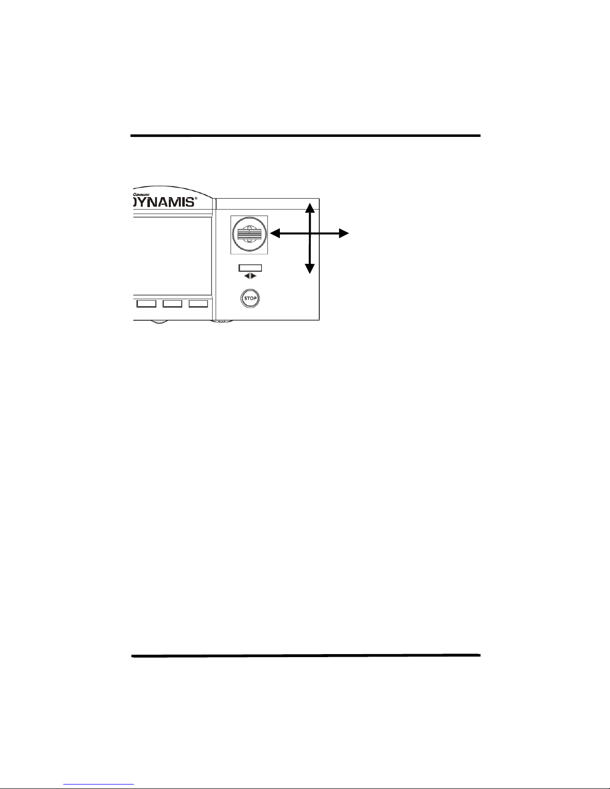
How to use the joystick
Increase speed, scroll through menus, text input
Scroll through
locomotives roster
and menus, text
input
Decrease speed, scroll
through menus, text input
9
. Push the joystick upwards to move the locomotive, bring it downwards to bring
the joystick.
10
. Leaving the first train running, select a second locomotive address using the
scrolling with the Joystick. When selecting another moving train the bar graph for
speed immediately shows current speed of that train so that any change to speed is
made from the speed at which it is currently travelling.
How to configure the locomotive roster
There is a 40 locomotive roster database recording details of the locos. When first
selecting a locomotive address to run a roster entry is created with default values.
Once there are 40 roster entries one must be deleted to allow any other
locomotives to be run.
EXAMPLE: Changing the address and defaults of locomotive
Long addresses (“4-digit”) must be written to a decoder by programming using a
Service Track with no other locomotives present otherwise all locomotives will

Dynamis User Guide
10
adopt the address. If necessary create a separate length of track powered by your
Dynamis for this purposes. Short addresses (“2-digit”) can be written to a decoder
using Main Track programming with other locomotives on the track.
The screen shows
LOC 0003 0:28
LOCOMOTIVE 0003
1. Changing the locomotive address
The locomotive address can be set in either of two ways
Service Track - all addresses 0001 to 9999
Main Track - short addresses 1 to 127 only
Using Main Track to change a short address to another short address
[MENU] -- scroll to
-- scroll to
Screen shows
[BKSP] to delete existing address
Use alphanumeric keys or joystick to enter new address up to 127
WRITE ADDR 68
Press [PROG] to write the new address
Both decoder and roster database are updated.
Using Service Track
[MENU] -- scroll to
-- scroll to
ON SERVICETRACK
PROGRAM
WRITE ADDR 0003
ON MAINTRACK
CHANGE ADDR LOC
WRITE ADDR 3
CHANGE ADDR 0003
PROGRAM
WRITE ADDR 0003
[ACCEPT]
[ACCEPT]
[ACCEPT]
[ACCEPT]
 Loading...