

Page 1

WARRANTY
Bacharach, Inc. warrants to Buyer that at the time of delivery this Product
will be free from defects in material and manufac ture and will conform
substan tially to Bacharach Inc.’s applicable speci cations. Bacharach’s
liability and Buyer’s remedy under this warranty are limited to the repair
or replacement, at Bacharach’s option, of this Product or parts thereof
returned to Seller at the factory of manufacture and shown to Bacharach
Inc.’s reason able satisfaction to have been defective; provided that written
notice of the defect shall have been given by Buyer to Bacharach Inc.
within one (1) year after the date of delivery of this Product by Bacharach,
Inc. For full details concerning this warranty, contact Bacharach Inc.
DRAFT GAUGE
Instruction 0013-9009
Rev. 5 - May 2010
World Headquarters
621 Hunt Valley Circle, New Kensington, PA 15068
Ph: 724-334-5000 • Fax: 724-334-5001 • Toll Free: 800-736-4666
Website: www.mybacharach.com • E-mail: help@mybacharach.com
Printed in U.S.A. ®Registered Trademark
Page 2

2 Figure 1. Draft Gauge
Mounting the Instrument
For portable use stand the gauge on a reasonably level surface
convenient to the location for checking draft. Gauge may also be
hung in an upright position using Ë(Slotted Recess) to receive a
nail or screw head. For permanent installation remove Ì (Screws)
and front cover, fasten to panel with two number 8 screws thru
Í(Mounting Holes), replace front cover and Ì (Screws). Never
locate gauge where temperature exceeds 110° F.
Connections
For portable use connect the gauge to a furnace with the 9 foot
length of rubber tubing and metal draft tube provided. For permanent installation, make connection from panel to draft measuring point with copper tubing or pipe, solid tubing (no fi ttings)
is preferred. At the end of the tubing provide a small tee with
a short piece of rubber tubing as shown in Figure 3. Connecting lines over 50 feet in length is not recommended. Use as few
bends as possible, and keep the connecting line to a minimum
length. The following tubing sizes are recommended:
Up to 10 foot length 1/4 inch ID tubing
Up to 25 foot length 3/8 inch ID tubing
Up to 50 foot length 1/2 inch ID tubing
Zero Adjusting
When checking for zero, hold the draft tube near gauge or if
permanently connected, break connecting line at panel. Zero is
adjusted by moving É(Adjusting Tab) until the pointer is in line
with the scales zero. For portable use, check zero each time the
gauge is set up for use. For permanent installations (always disconnect the hose from the gauge before making the zero check)
check zero at one or two week intervals. 3
Page 3

Figure 2. Draft Gauge Parts
5
4
Parts List for the Draft Gauge
0013-0014 Scale +.05 <0> –.25” H2O
0013-0015 Scale +.05 <0> –1.0” H2O
0013-0016 Scale +1 <0> –25mm H2O
0013-0017 Scale +1 <0> –5mm H2O
0013-0159 Scale +1 <0> –15mm H2O
0013-0056 Leaf Spring Assembly for +.05” <0> –.25” or +1 <0> –5mm H2O Range
0013-0057 Leaf Spring Assembly for +.05” <0> –1.0” or +1 <0> –25mm H2O Range
0013-0058 Leaf Spring Assembly for +1” <0> –15” H
2
O Range
0013-0006 Window
0013-0024 Screw
0013-0025 Screw
0013-0029 Pointer Assy
0013-0033 Calibrating Arm
0013-0034 Slide Stud
0013-0036 Washer
0013-0046 Draft Tube
0013-0047 Tubing
0013-0049 Cradle & Zero Adjuster
0013-0050 Diaphragm Cover
0013-0055 Diaphragm Assy
0013-0060 Back Cover
0013-0128 Front Cover
0013-0134 Front Cover Assy
0001-0627 Screws
0001-1636 Screws
0001-1974 Screws
0001-2486 Screw
0001-5107 Screw
0001-5110 Screw
0002-2160 Screws
0002-2986 Lock Nuts
0002-2990 Hex Nut
0002-3735 Speed Nuts
0002-4708 Washer
0005-4703 Pointer Stops
Page 4
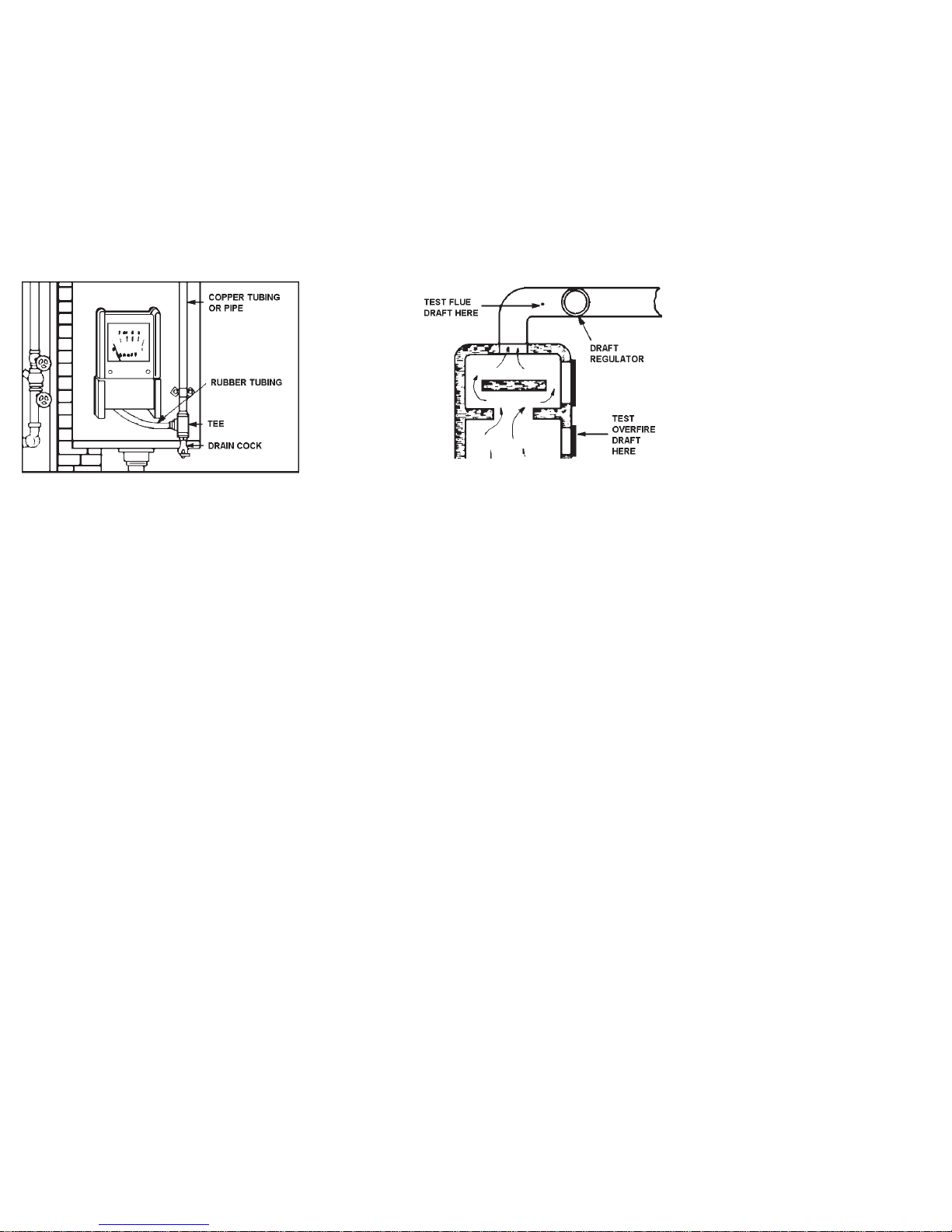
Locations for Checking Draft
Furnace manufacturer may require measurement of draft (a) in
fl ue between regulator and furnace or (b) overfi re between com-
bustion space and heat exchanger (Figure 4). Locate sampling
hole in fl ue 6” or more from draft regulator or damper toward
furnace. Use awl with ¼ shank for forming draft hole in light
sheet metal. Make overfi re measurement through blot hole in
door or through air louvers. If necessary, drill ¼ hole. In case of
over sized hole or masonry setting, draft tube (replace with
1/8’ pipe if necessary) should be inserted several inches beyond
inside surface of fl ue pipe or furnace wall. For detailed instruc-
tions on check locations, see manufacturer’s service or installation manual.
6
Figure 3. Mounting Draft Gauge
Figure 4. Draft Gauge Locations
Measuring Draft
Allow furnace to operate for several minutes, unwrap hose, place
gauge on reasonably level surface, check zero, insert metal draft
tube through draft hole. After about 30 seconds read draft from
gauge scale.
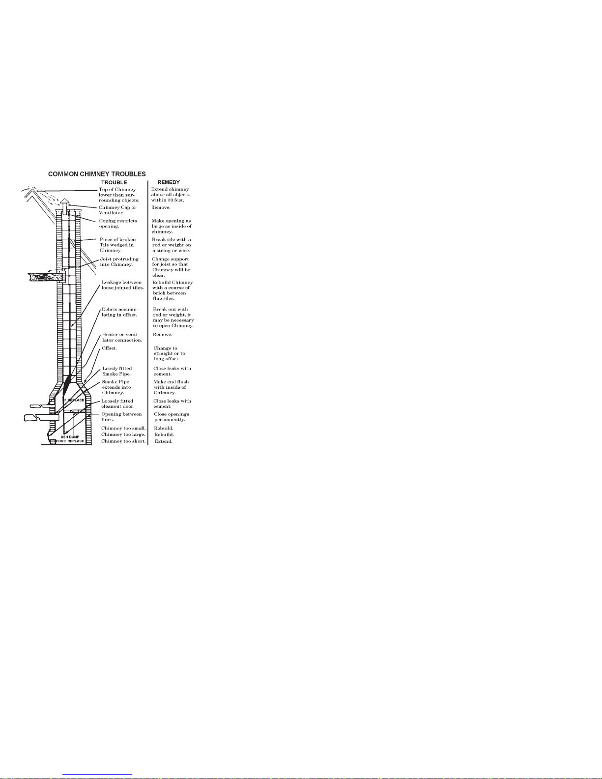
Correct Draft
Recommendations for draft required for good performance must
be obtained from the heating equipment manufacturer’s installation or service manual. Some common causes of poor draft are
shown in “Common Chimney Troubles”.
Maintenance
Do not oil this gauge. Protect the gauge from shock, vibration
and exposure to excessively high temperatures. 7
Page 5
8
 Loading...