

Page 1

INSTRUCTION 2772-0803
REMOTE INTELLIGENT SENSOR
AREA MONITOR
Installation/Operation/Maintenance
Rev. 14 – February 2004 (CN #3252)
®
251 Welsh Pool Road
Website: www.scottinstruments.com • www.bacharach-inc.com
Ph: 610-363-5450 • Fax: 610-363-0167
Printed in U.S.A. ®Registered Trademark
Exton, PA 19341
Page 2

Declaration of Conformity
Manufacturer's Name: SCOTT INSTRUMENTS
Manufacturer's Address: 251 Welsh Pool Road
Exton, PA 19341 USA
Product Name: Remote Intelligent Sensor
Conforms to the following product specifications
EMC: European Directive 89/336/EEC
EN 500081-1 (Emissions)
EN 500082-1 (Immunity)
A
Page 3

REMOTE INTELLIGENT SENSOR - AREA MONITOR
CONTENTS
Page #
FEATURES .................................................................................................................................... v
PRODUCT SPECIFICATION ...........................................................................................................vi
RIS CATALOG NUMBERS & DATA ............................................................................................. viii
1 INTRODUCTION ........................................................................................................................... 1-1
1.1 SYSTEM DESCRIPTION .......................................................................................................... 1-1
1.2 BASIC PRINCIPLES ................................................................................................................. 1-1
1.3 GENERAL DESCRIPTION ....................................................................................................... 1-1
1.3.1 ENCLOSURE................................................................................................................ 1-1
1.3.2 CABLE GLANDS .......................................................................................................... 1-1
1.3.3 MAIN SYSTEM BOARD .............................................................................................. 1-1
1.3.4 SYSTEM POWER SWITCH SW1 ............................................................................... 1-2
1.3.5 MECHANICAL CHASSIS ............................................................................................ 1-2
1.3.6 BACK-UP BATTERY ................................................................................................... 1-2
1.3.7 BASE BOARD ............................................................................................................... 1-2
1.3.8 SAMPLE INLET........................................................................................................... 1-3
2 INSTALLATION AND SYSTEM CHECK .................................................................................. 2-1
2.1 UNPACKING ............................................................................................................................. 2-1
2.2 BATTERY CONNECTION........................................................................................................ 2-1
2.3 MECHANICAL INSTALLATION ............................................................................................ 2-1
2.4 ELECTRICAL INSTALLATION .............................................................................................. 2-1
2.4.1 CABLE RECOMMENDATION .................................................................................... 2-1
2.4.1.1 PSU to RIS Input ................................................................................................... 2-1
2.4.1.2 PSU to Alarm Module ........................................................................................... 2-1
2.4.1.3 RIS Relay Output to Alarm Module ..................................................................... 2-1
2.4.1.4 0 – 1V Analog Output ............................................................................................ 2-1
2.4.1.5 4 – 20 mA Analog Output ..................................................................................... 2-1
2.4.2 POWER SUPPLY AND INPUT CONNECTIONS ................................................... 2-1
2.4.3 OUTPUT CONNECTIONS ......................................................................................... 2-2
2.4.4 RELAY OUTPUTS ....................................................................................................... 2-2
2.4.5 ANALOG OUTPUTS ................................................................................................... 2-2
2.5 SYSTEM POWER SUPPLY CONSIDERATION & SELECTION ........................................ 2-2
2.5.1 RIS POWER SUPPLIES .............................................................................................. 2-2
2.5.1.1 ‘Single Point’ .......................................................................................................... 2-2
2.5.1.2 ‘Multi Point’ ........................................................................................................... 2-2
2.5.2 POWER REQUIREMENTS, RIS & ALARM MODULE ........................................... 2-3
2.5.2.1 Low Flow RIS Models ............................................................................................ 2-3
2.5.2.2 High Flow RIS Models ........................................................................................... 2-3
2.5.2.3 ‘Worst Case’ Currents ........................................................................................... 2-3
2.5.2.4 Alarm Module......................................................................................................... 2-3
2.5.2.5 Summary ‘Worst Case’ Input Currents .............................................................. 2-3
2.6 SAMPLE LINES ........................................................................................................................ 2-3
2.6.1 GENERAL ..................................................................................................................... 2-3
2.6.2 LESS REACTIVE GASES ............................................................................................ 2-3
2.6.3 REACTIVE GASES ....................................................................................................... 2-4
2.6.4 SYSTEM PERFORMANCE WITH EXTENDED SAMPLE LINES ........................ 2-4
2.7 0 – 1 VOLT CONVERSION ...................................................................................................... 2-4
2.7.1 TOOLS & MATERIALS REQUIRED ......................................................................... 2-4
2.7.2 PROCEDURE................................................................................................................ 2-4
Instruction 2772-0803 Page i
Page 4

REMOTE INTELLIGENT SENSOR - AREA MONITOR
CONTENTS (continued)
2.8 SYSTEM CHECK ....................................................................................................................... 2-4
2.8.1 TAPE CASSETTE LOADING ..................................................................................... 2-4
2.8.2 CHECK AND ADJUST SYSTEM PARAMETERS .................................................... 2-5
2.8.2.1 V, System Voltage ................................................................................................. 2-5
2.8.2.2 mA, ‘Charger Current’ ......................................................................................... 2-5
2.8.2.3 Alarm Set Points .................................................................................................. 2-5
2.8.2.4 Alarm Level 1 and 2 ............................................................................................. 2-5
2.8.2.5 Gas Curve .............................................................................................................. 2-6
2.8.2.6 Multi Gas Curve Systems .................................................................................... 2-6
2.8.2.7 Light Levels Track 1 & 2 .................................................................................... 2-6
2.8.2.8 Flow Rate ............................................................................................................... 2-6
2.8.2.9 Date & Time ......................................................................................................... 2-6
2.8.2.10 Interruption of TEST Mode Cycle ...................................................................... 2-7
2.8.2.11 Completion of Checks .......................................................................................... 2-7
2.9 OPTION PCB INSTALLATION .............................................................................................. 2-7
2.9.1 PRINTER (OPTION) INTERFACE INSTALLATION ............................................. 2-7
2.9.2 PORTABLE PRINTER ................................................................................................. 2-7
2.9.3 ALARM MODULE CONNECTION ............................................................................ 2-7
2.9.4 RELAY ALARM INSTALLATION ............................................................................. 2-7
3 SYSTEM OPERATION AND FEATURES ................................................................................ 3-1
3.1 COMPLETE SAMPLING SEQUENCE ................................................................................... 3-1
3.1.1 AUTOMATIC PURGE CYCLE ................................................................................... 3-1
3.1.2 TWIN TRACK TAPE SAMPLING ............................................................................. 3-1
3.1.3 TAPE REFERENCE MEASUREMENT ..................................................................... 3-1
3.2 DENSITY AND TIME OPERATING MODES ........................................................................ 3-2
3.2.1 DENSITY MODE .......................................................................................................... 3-2
3.2.2 TIME MODE ................................................................................................................. 3-2
3.3 CHANGE-OVER FROM DENSITY TO TIME MODE ........................................................... 3-2
3.4 MIMINUM SAMPLE TIME ..................................................................................................... 3-2
3.5 TAPE CASSETTE LIFE ............................................................................................................ 3-2
3.6 DATA POINT STORAGE .......................................................................................................... 3-2
3.7 SYSTEM DISPLAY .................................................................................................................... 3-2
3.7.1 SYSTEM NORMAL, GAS CONCENTRATION ZERO OR LOW. ........................... 3-2
3.7.2 SYSTEM NORMAL, GAS CONCENTRATION ABOVE THE
ALARM THRESHOLD ................................................................................................. 3-3
3.7.3 OVERRANGE ALARM ................................................................................................. 3-3
3.7.4 SYSTEM FAULT .......................................................................................................... 3-3
3.8 SYSTEM ALARMS ..................................................................................................................... 3-3
3.8.1 GAS ALARM ................................................................................................................. 3-3
3.8.2 ADDITIONAL GAS ALARM SET POINT ................................................................. 3-3
3.8.3 FAULT RELAY ............................................................................................................ 3-4
3.9 DIAGNOSTICS .......................................................................................................................... 3-4
3.10 TEST MODE ............................................................................................................................ 3-4
3.11 KEYPAD FUNCTION ............................................................................................................ 3-4
3.11.1 ‘HOLD/RELEASE’ KEY ............................................................................................... 3-4
3.11.2 ‘PRINT’ KEY ................................................................................................................. 3-4
3.11.3 ‘15 MIN TWA (DECADE)’ KEY .................................................................................. 3-4
3.11.4 ‘8 HR TWA (DIGIT SET)’ KEY .................................................................................... 3-4
3.12 USING THE KEYBOARD ....................................................................................................... 3-4
Page ii Instruction 2772-0803
Page 5

REMOTE INTELLIGENT SENSOR - AREA MONITOR
CONTENTS (continued)
3.13 OPTIONAL FEATURES ......................................................................................................... 3-4
3.13.1 RELAY ALARM OPTION............................................................................................ 3-4
3.13.2 PRINTER INTERFACE OPTION ..............................................................................3-4
3.13.3 TEST CARD ..................................................................................................................3-4
3.14 PRINTER OPERATION & USE (OPTIONAL FEATURE) ................................................. 3-5
3.14.1 GENERAL ..................................................................................................................... 3-5
3.14.2 PRINTER SPECIFICATION ...................................................................................... 3-5
3.14.3 PRINTOUT MODES ..................................................................................................... 3-6
3.14.3.1 Printing 'On Line' ................................................................................................. 3-6
3.14.3.2 Print at Intervals ..................................................................................................3-6
3.14.3.3 Print on Command ................................................................................................ 3-6
3.14.3.4 Printed Date Format ............................................................................................ 3-7
3.14.3.5 Data Storage up to 7 Days ....................................................................................3-7
3.14.3.6 Preventing Data Loss ........................................................................................... 3-7
3.14.4 PRINTER CARD DESCRIPTION .............................................................................. 3-7
3.14.4.1 Real Time Clock .................................................................................................... 3-7
3.14.4.2 Data Storage .......................................................................................................... 3-7
3.14.4.3 Data Communication ............................................................................................ 3-7
3.14.4.4 Selection of Printer Baud Rate ............................................................................ 3-7
3.14.5 CONNECTING A PRINTER ....................................................................................... 3-7
3.14.5.1 GMD Printer Connection ..................................................................................... 3-7
3.14.5.2 Connecting a Non-GMD Printer .......................................................................... 3-8
3.14.5.3 Portable Use of a Non-GMD Printer ....................................................................3-8
4 MAINTENANCE AND TROUBLESHOOTING ................................................................... 4-1
4.1 MAINTENANCE GENERAL.......................................................................................... 4-1
4.2 VERIFYING THAT A GAS ALARM WAS CAUSED BY GAS .................................... 4-1
4.3 CLEARING A SPURIOUS ALARM ............................................................................... 4-1
4.4 ADJUST LIGHT LEVELS .............................................................................................. 4-1
4.5 CHECKING AND ADJUST SYSTEM FLOW RATE .................................................. 4-2
4.6 DISABLING THE ‘DOOR OPEN’ ALARM ................................................................... 4-2
4.7 ADJUST THE DOOR SWITCH ..................................................................................... 4-2
4.8 MEASURING PUMP CURRENT .................................................................................. 4-3
4.9 RESETTING THE PRINTER OPTION STORAGE .................................................... 4-3
4.10 CLEANING THE SAMPLING INPUT AND OPTICS BLOCK ................................. 4-3
4.10.1 INTRODUCTION............................................................................................. 4-3
4.10.2 LIGHT LEVEL ADJUSTMENT ..................................................................... 4-3
4.10.3 WHEN TO CLEAN .......................................................................................... 4-3
4.10.4 HOW TO CLEAN ............................................................................................. 4-4
4.10.5 DIRECT CLEANING OF THE LED’S AND PHOTO DIODES .................. 4-4
4.10.6 REPLACING THE OPTICS BLOCK ............................................................. 4-4
4.10.7 WHAT TO DO IF CLEANING DOES NOT RECTIFY THE PROBLEM .. 4-5
4.11 CHANGING A PUMP. .................................................................................................... 4-5
4.11.1 PREPARATION ................................................................................................ 4-6
4.11.2 REMOVAL OF THE MECHANICAL CHASSIS ........................................... 4-6
4.11.3 PUMP REMOVAL ............................................................................................ 4-6
4.14.4 FITTING THE NEW PUMP........................................................................... 4-6
4.14.5 REPLACING THE MECHANICAL CHASSIS AND
SETTING PUMP FLOW ................................................................................ 4-6
Instruction 2772-0803 Page iii
Page 6

REMOTE INTELLIGENT SENSOR - AREA MONITOR
CONTENTS (continued)
4.12 EXTERIOR CLEANING ................................................................................................. 4-6
4.13 KEY PARAMETER CHECKS ......................................................................................... 4-6
4.14 MECHANICAL TIGHTNESS ......................................................................................... 4-7
4.14.1 CABLE GLANDS ............................................................................................. 4-7
4.14.2 DOOR SWITCH ................................................................................................ 4-7
4.14.3 DOOR SEALS ................................................................................................... 4-7
4.14.4 SAMPLE INLET .............................................................................................. 4-7
4.14.5 INTERFACE TERMINAL SCREWS .............................................................. 4-7
4.15 INPUT PATH CLEANING ............................................................................................ 4-7
4.16 PUMP CHECK ................................................................................................................ 4-7
4.17 CHARCOAL FILTER & TUBING CHECK .................................................................. 4-7
4.18 TROUBLESHOOTING GENERAL ............................................................................... 4-7
4.19 EXCESSIVE INPUT CURRENT ................................................................................... 4-7
4.19.1 HIGH CHARGING CURRENT....................................................................... 4-7
4.19.2 HIGH PUMP CURRENT ................................................................................ 4-7
4.20 LOW PUMP FLOW ........................................................................................................ 4-7
4.20.1 A FAULTY PUMP ........................................................................................... 4-8
4.20.2 A BADLY FITTED INPUT TUBE ................................................................. 4-8
4.20.3 A FAULTY TAPE GATE SEAL...................................................................... 4-8
4.20.4 LEAKING OR LOOSE TUBING .................................................................... 4-8
4.21 EXCESSIVE TAPE USE ................................................................................................. 4-8
4.21.1 MONITORED CONCENTRATION LEVELS HIGH .................................... 4-8
4.21.2 EXCESSIVE STEP LENGTH ......................................................................... 4-8
4.22 TAPE BREAKAGE .......................................................................................................... 4-8
4.23 LIGHT FAULTS .............................................................................................................. 4-8
4.24 DOOR FAULT ................................................................................................................. 4-8
5 SYSTEM SPARE PARTS ........................................................................................................ 5-1
5.1 MODEL DEPENDENT PARTS ..................................................................................... 5-1
5.1.1 CASSETTE ........................................................................................................ 5-1
5.1.2 OPTICS BLOCK ............................................................................................... 5-1
5.1.3 BACK-UP BATTERY ....................................................................................... 5-1
5.1.4 PUMP ASSEMBLY .......................................................................................... 5-1
5.2 SYSTEM POWER SUPPLIES ....................................................................................... 5-1
5.2.1 ‘SINGLE POINT’ ............................................................................................. 5-1
5.2.2 ‘MULTIPOINT’ ................................................................................................ 5-1
5.3 RECOMMENDED SPARES ............................................................................................ 5-1
5.4 COMMON PARTS ........................................................................................................... 5-2
5.5 OPTIONS AND SUPPLIES ........................................................................................... 5-2
5.6 SERVICE CENTERS ....................................................................................................... 5-2
SUPPLEMENT A ............................................................................................................................ S-A1
A1 EARLIER IRS BASE BOARDS ....................................................................................... S-A1
A1.1 ADJUSTING LIGHT LEVELS ON PHASE 1 RIS UNITS ......................... S-A1
RIS TEST/FAULT PARAMETER LOG SHEET
Page iv Instruction 2772-0803
Page 7

REMOTE INTELLIGENT SENSOR - AREA MONITOR
FEATURES
• TRUE CONTINUOUS MONITORING WITH RELIABLE PAPER TAPE DETECTION
Using GMD developed, optimized and proven tape technology.
• MICROPROCESSOR CONTROLLED AND SOLID STATE LOGIC
For reliability, flexibility and calibration stability.
• QUICK RESPONSE & AUTORANGING
Sophisticated, dynamic control of the sampling sequence provides a response time as low as 15
seconds, excellent resolution of short term peaks and economic use of tape.
• LOCAL OR REMOTE WARNING
Highly visible display of measured concentration, system status, gas and system fault alarms.
Remote warnings of gas and fault alarms via solid state relay interface. Optional audible and visual
alarm module provides high impact additional warning.
• CONTINUOUS DIAGNOSTICS & SYSTEM TEST MODE
Monitors the status of key parameters and enables the system to be kept in optimum condition.
• BATTERY BACKUP
Integral backup battery automatically provides supply failure protection.
• USER SELECTABLE ALARM SET POINTS
The default values assigned may be set at any value in the detection range through the system
keyboard.
• UP TO FOUR WEEK CASSETTE WITH INTEGRAL PURGE FILTER
One piece design eliminates tape handling and provides economy of use.
• SYSTEM EXPANSION
Comprehensive area monitor schemes can be built one point at a time, each selected to measure
the gas required.
• OPTIONAL FEATURES
Printer option with storage of up to 7 days worth of data points.
Instruction 2772-0803 Page v
Page 8

REMOTE INTELLIGENT SENSOR - AREA MONITOR
PRODUCT SPECIFICATION
ACCURACY
PHYSICAL
Dimensions: 7" Depth x 11.75" Width x 7.875" Height
Weight: 11.5 lbs. (5.2 Kg.).
Enclosure: IP-55 with sealed glands (NEMA 4).
Cable Glands: 3 x for input/output cables. Pre-wired connector for Optional Printer.
POWER INPUT REQUIREMENTS
External Power Supply: 12VDC
Input Current: Depends upon model and conditions.
Low Flow models: (200cc/min or less) Cat.# 2772-0010/015/020/030/035/040/060/
High Flow models: (700cc/min or less) Cat.#272-0120/160/175 etc.
ppb Ranges: ± 15 % of reading ± 1 ppb.
ppm Ranges: ± 15 % of reading ± 0.01 ppm.
2772-0020: ± 20 % of reading ± 0.01 ppm.
2772-0035: ± 20 % of reading ± 0.02 ppm.
(178mm D x 298mm W x 200mm H)
090/095/100/110/150 etc.
Normal run current (charged battery) =150–200mA
Run current (discharged battery) =500–700mA
Normal run current, (charged battery) =250–300mA
Run current (discharged battery) =600–800mA
OUTPUTS
Solid State ‘Relay’ Output:
Standard System: 1 Combined Gas/ Fault Alarm.
Optionally: 2 Gas Alarms plus 1 Fault Alarm, or
Devices rated @ 1A./60 V DC max.
Surge current (1 second) = 5A peak.
Turn on/off time = 50, ms.
On state voltage = 1.5V DC
Off state leakage at 60 V DC across the load = 200, µA
Logic: Device normally ‘closed’, opens on alarm
(with standard system software).
Analog Output:
Standard: 4–20 mA is default on the instrument.
0–1 V DC can be hardware selected.
In both cases the minimum = zero concentration,
and the maximum value = system range maximum.
(Other configurations available. Contact Customer Service)
Page vi Instruction 2772-0803
Page 9

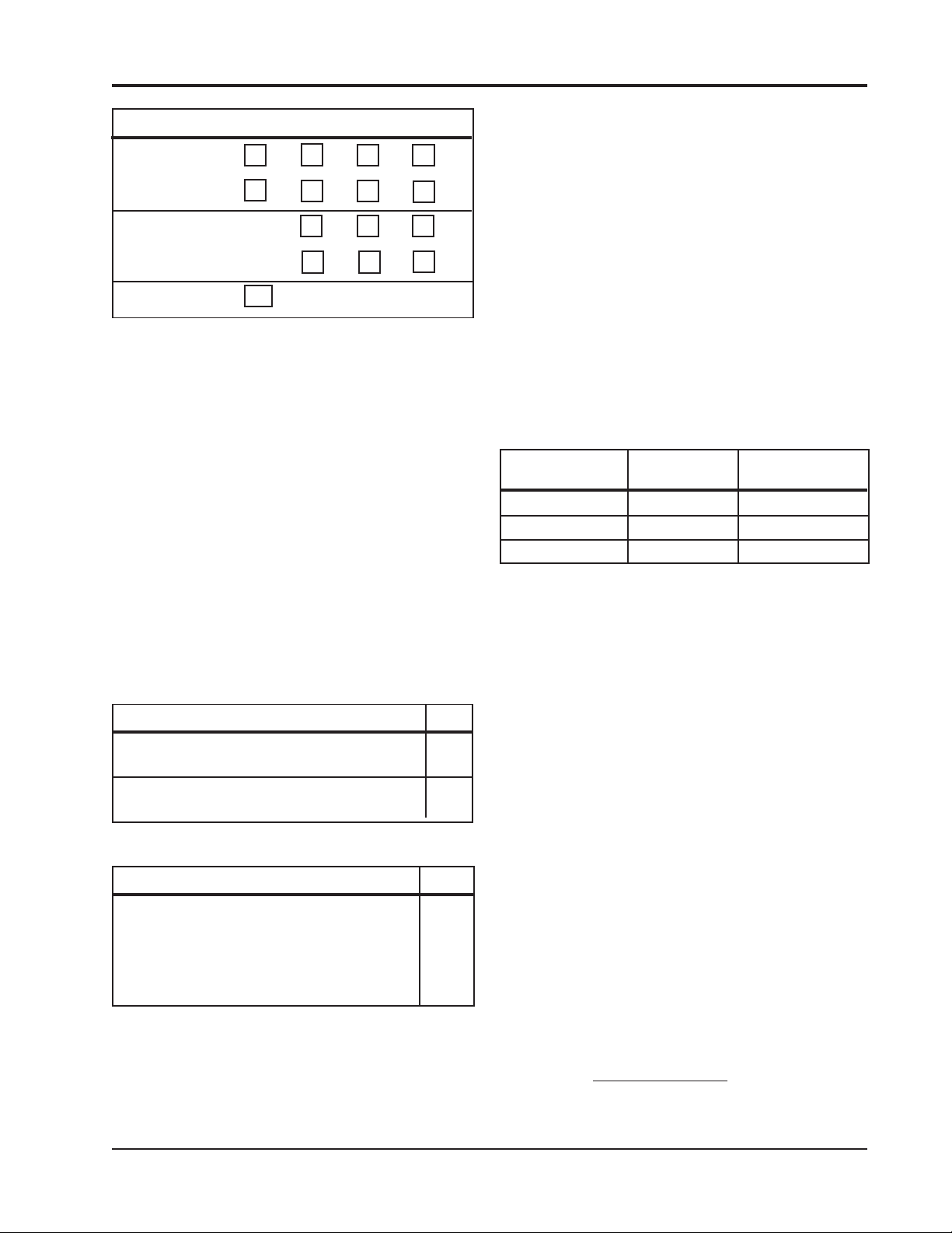
DISPLAY
Custom LCD Display: Area measures 5.7" (145mm) x 3.2" (81 mm).
Displayed parameters
include:
In the TEST Mode, display
includes:
Alpha/Numeric characters: 0.92" (23.4mm) high.
KEYBOARD
Membrane Switch Panel: Four switches for the following functions:
REMOTE INTELLIGENT SENSOR - AREA MONITOR
PRODUCT SPECIFICATION (continued)
System Readiness status,
Measured Concentration (3 decades of ppb or ppm),
Tape Remaining, and Icons for Gas & Fault alarms.
Alarm Set Point(s), System Current (mA),
Alarm Type, Regulated Voltage (V), Active Gas Type,
Track 1 & 2 Light Levels, and, Date & Time (with optional
Serial Printer Interface PCB, Section 5).
PRINT, 8 HR. TWA /DIGIT SET, 15 MIN TWA/DECADE,
& HOLD/RELEASE.
INTERNAL BACK-UP BATTERY
Sealed Lead Acid Battery: 6 v / 1.1 Ah Charge maintained with external power connected.
(the internal power switch SW1 can be on or off).
ENVIRONMENTAL
Temperature Range: –10 °C to +40 °C ( operating)
(Instrument Only) Relative Humidity (System Hardware): 5–95% (non-condensing).
SAMPLING INPUT
FEP: Teflon input tubes
OPTIONS
Printer option: TTL serial interface and 7-Day memory.
Three (3) Relay option: 2 x gas alarm outputs with adjustable set point and 1 x fault
alarm output.
CATALOG #, CASSETTE #,
RANGES and MODEL
DEPENDENT PARAMETERS: See RIS Catalog Numbers and Data (Table #1).
Instruction 2772-0803 Page vii
Page 10

REMOTE INTELLIGENT SENSOR - AREA MONITOR
TABLE #1
RIS CATALOG NUMBERS & DATA
CATALOG
NUMBER
2772-0010 TDI 0 1000 ppb 200 5 10 100
2772-0015 TDI HIGH RANGE 5 2000 ppb 200 5 10 2000
2772-0020 HYDRAZINES 1 2.00 ppm 200 0.05 0.10 2.00
2772-0030 PHOSGENE (A) 3 5.00 ppm 100 0.05 0.10 0.30
2772-0035 VELCORIN® 35 2.00 ppm 200 0.05 0.10 2.00
2772-0040 CHLORINE 7 2.00 ppm 170 0.05 0.10 2.00
2772-0060 ARS INE 8 1000 ppb 200 25 50 100
2772-0090 ACID GASES 9 2.00 ppm 150 0.05 0.10 2.00
2772-0095 HCl HIGH RESOLUTION 10 100 ppb 250 5 10 100
2772-0100 HDI 2 500 ppb 200 5 10 500
2772-0110 PHOSGENE (B) 4 5.00 ppm 100 0.05 0.10 5.00
2772-0120* MDI 6 200 ppb 700 5 10 200
2772-0150 IPDI 12 1000 ppb 200 5 10 100
2772-0160* MDI, TDI, IPDI 97
2772-0175* TDI HIGH FLOW* 14 100 ppb 700 5 10 100
GAS TYPE
GAS
CODE
RANGE UNITS
200 MDI
100 TDI
200 IPDI
ppb 700 5 10 200
FLOW
RATE
ALARM
LEV EL 1
ALARM
LEVEL 2
ANALOG
OUTPUT
* High Flow, all others are Low Flow
Page viii Instruction 2772-0803
Page 11
REMOTE INTELLIGENT SENSOR - AREA MONITOR
1 INTRODUCTION
1.1 SYSTEM DESCRIPTION
A range of Remote Intelligent Sensors (RIS) are
available. Each is designed to measure low concentrations of a specific gas. Multiple RIS systems can
be connected into a control network to provide an
area monitoring capability with central supervision.
The RIS is a single point, microprocessor
controlled, instrument for use in a fixed location.
Two RIS versions were produced (see Supplement A
for units built before April '92).
The RIS is housed in an environmentally sealed
enclosure and is line-powered, via a DC power
supply, for continuous monitoring. An internal
backup battery is provided as protection against
power interruptions.
The standard system provides clear visual
indication of status, concentration level, 4-20 ma
analog output, gas, and fault alarm conditions.
TWA’s, 15 minute and 8 hour, are displayed at the
touch of a keyboard button.
Reliable and effective operation is assured by
on-line self-diagnostic routines. An easy-to-use
TEST Mode allows key parameters to be checked
and adjusted.
Optional features provide storage, and printout,
of up to one week’s data points, two independently
selectable (via keypad) alarm relays with a separate
fault indication relay and a hardware selectable 0-1
VDC analog output (Sections 2.4.5 & 2.7).
This combination of operating features gives long
tape cassette life at low sampling levels, and a rapid
response with excellent tracking of short term peaks
as levels rise.
The detection of a gas concentration that is higher
than the user-adjustable alarm set point, results in a
highly visible warning on the RIS's large custom
display. In addition, local and remote external warning
devices or systems can be activated via interface
signals.
1.3 GENERAL DESCRIPTION
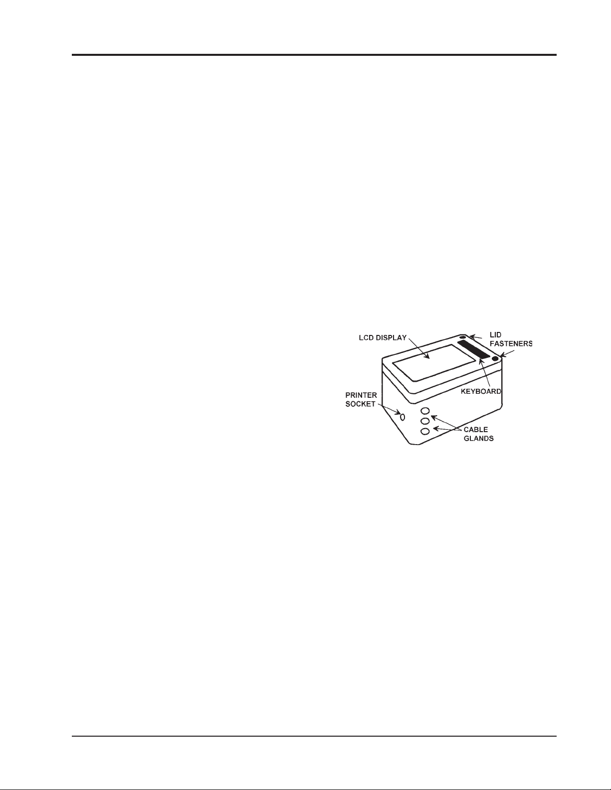
1.3.1 ENCLOSURE. The instrument is contained
within a tough, IP-55 rated, enclosure that is
suitable for installation inside and out. A large
liquid crystal display (LCD) is mounted in the front
face of the door next to a membrane keyboard that is
used for programming certain functions.
1.2 BASIC PRINCIPLES
A measured sample volume is drawn into the
RIS and passed through a chemically impregnated
paper tape. The tape reacts to the presence of a
specific gas by developing a stain whose intensity is
proportional to the sample concentration.
A beam of light is bounced off the tape and the
reflected light is measured. The difference in
reflected light values, developed before and after
the stain, is used to calculate stain intensity,
enabling the sampled gas concentration to be
determined.
The measurement of low gas concentration
levels takes place during a fixed four minute sample
period. If the sample concentration rises above a
predetermined value, the operating mode changes
and the system measures the time taken for a given
stain value to develope.
This technique provides a wide dynamic range,
good resolution and a rapid response to rising gas
levels. In addition, the tape never becomes saturated
which ensures accurate measurement, and toxic gases
are prevented from breaking through the tape into the
system. A double track, tape management system
gives maximum tape economy.
Figure 1-1. Enclosure
The door is hinged on one side and secured shut
by two screw fasteners, which are opened with a
special key to discourage unauthorized tampering.
The door hinges are easily disengaged and removal of
the door from the base is quick and simple, should
this ever be required.
A door-open fault display icon, and relay output
provide warnings and help ensure that RIS is only
operated when the enclosure is secured shut.
There are threaded mounting holes in the base
of the enclosure. The mounting brackets are supplied with the system.
1.3.2 CABLE GLANDS. Three sealed glands are
provided for cable entry and exit. A socket is
provided at one end to allow the connection of an
optional printer.
1.3.3 MAIN SYSTEM BOARD. The board is
mounted on the rear face of the door and is accessible when the door is open. The red push-button
TEST Mode switch is in the bottom left-hand corner,
as viewed with the door open.
Instruction 2772-0803 Page 1-1
Page 12
DIP SWITCH 1
DO NOT TOUCH !!
LCD
ADJUST
POT.
EPROMS
DOOR
PROMIXITY
SWITCH
RED TEST BUTTON
REMOTE INTELLIGENT SENSOR - AREA MONITOR
DIP SWITCH 2
ON/OFF SWITCH SW1
VOLTAGE REGULATOR VR1
BATTERY
J5
FILTER
J1
CASSETTE
PRINTER
SOCKET
BATTERY PLUG
RIBBON
CABLE
INTERFACE
CABLE
OPTION
BOARD
B
A
MAIN BOARD
FLOW ADJUST POT.
CABLE GLANDS
TAPE GATE LEVER
TAPE
RESET
BUTTON
LIGHT
LEVEL
ADJUST
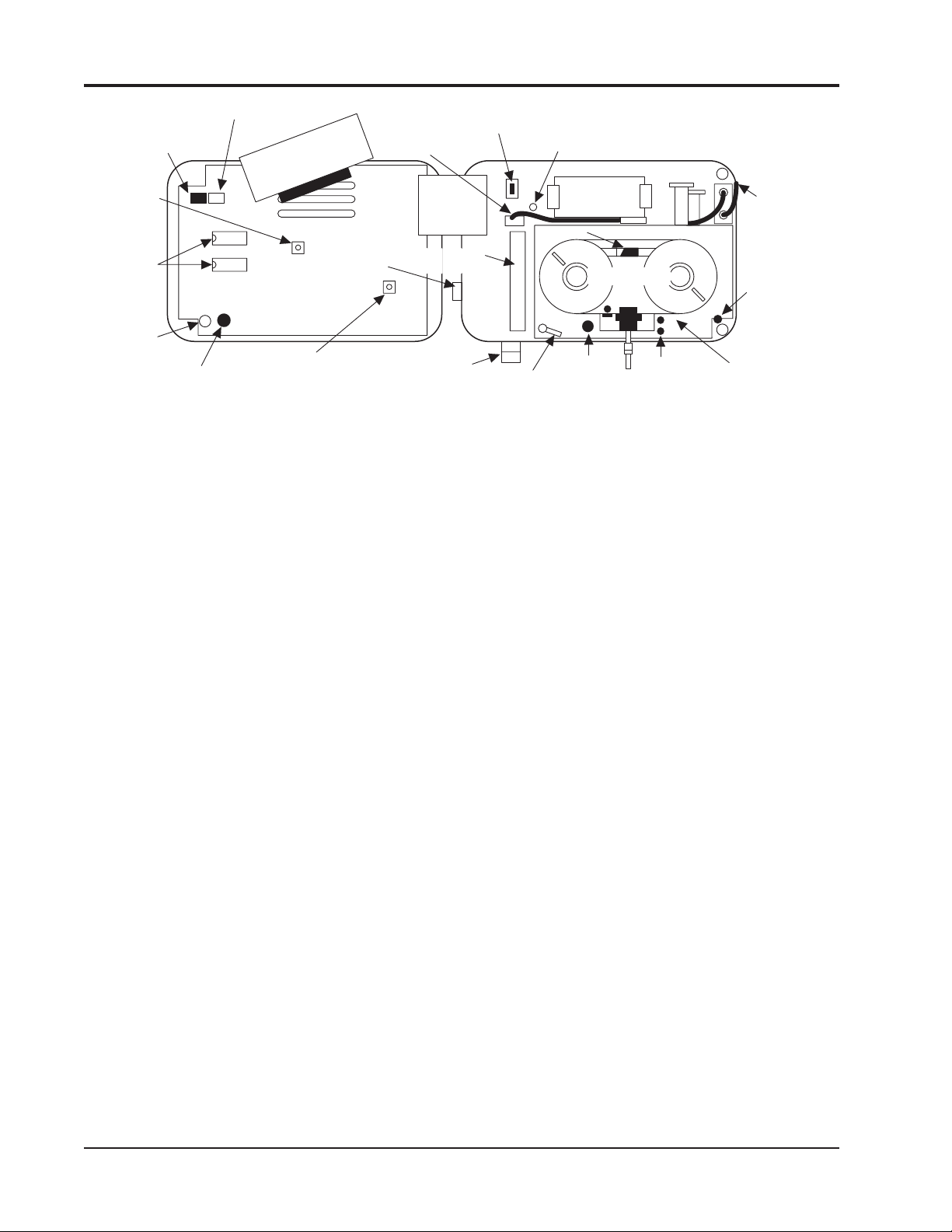
Figure 1-2. Door Open and Cover Removed from Back of Door
PNEUMATIC
HOSES AND
CONNECTOR
DOOR SWITCH
MAGNET
ADJUSTMENT
MECHNICAL
CHASSIS
On the main board are mounted several potentiometers and ‘dip’ switches. These should not normally be touched, particularly dip switch 1.
However, a potentiometer (POT) is provided for user
adjustment of the pump flow rate. The location of
the POT is shown in Figure 1-2 and an explanation
of how the flow rate is adjusted is provided in
Section 4.5.
System operating software is stored in two
EPROM’s that are fitted on the board and marked
with the version number. These devices should not
be normally touched or removed except if a factory
upgrade is received.
The main board is protected by a black molded
cover held on by two screws and two pegs.
1.3.4 SYSTEM POWER SWITCH SW1. RIS
operation is controlled by a switch mounted on the
base board. SW1 is located at the top left of the
right hand unit, see Figure 1-2.
When SW1 is ‘OFF’, the system is off. With the
switch ‘ON’, the system will operate from the external 12 volts input, or the systems back-up battery if the external power is disconnected, or fails.
1.3.5 MECHANICAL CHASSIS. This subassembly carries the optic block and its associated
PCB, the tape drive mechanism and take-up drive
clutch.
Also mounted on the chassis is the pump, with
the pneumatic elements and plumbing necessary for
the track switching and purge functions. The tape
cassette is mounted directly on the front face of the
chassis.
1.3.6 BACK-UP BATTERY. The lead acid battery is
located immediately above the mechanical chassis and is
secured to the system base board with metal clips. It is
connected to the system via a short cable plug and
socket (J5).
The battery is automatically ‘float charged’
whenever the RIS is connected to a 12 VDC supply.
The battery is charged with SW1 off or on. If the
RIS supply fails, the back-up battery will keep the
system running for 2-3 hours. The support time
depends upon the system type, specification, and the
battery condition.
If the RIS is being shipped, or will remain unused
and disconnected from the input supply for more than a
few days, it is good practice to disconnect the battery, at
the plug and socket.
NOTE: If the internal system switch, SW1,
is left on and the RIS input supply is
disconnected, the battery will discharge.
If the RIS input supply is disconnected, the
battery will discharge, irregardless of SW1
being on or off.
1.3.7 BASE BOARD. This is a printed circuit
board fixed to the base of the enclosure. It provides
the interconnection between the subassemblies
mounted on it and the main circuit board on the door.
Other circuit elements located on this board
include; the analog output, solid state output
‘relays’, interface terminal strip J1, voltage regulator potentiometer VR1 and system switch SW1.
The current Phase 2 boards have 3 solid state
‘relay’ devices. Terminal identification and numbering have varied and the appropriate interface
diagram should be used. Both versions are shown in
Figure 2-3.
NOTE: The earlier (Phase 1) versions
(Produced before April '92) are described in
Supplement A, in the rear of this manual.
The 3 ‘relay’ devices are standard, but only one
‘relay’ output is active and available unless the
optional Alarm Relay PCB (Section 5.5) is installed.
Page 1-2 Instruction 2772-0803
Page 13

REMOTE INTELLIGENT SENSOR - AREA MONITOR
1.3.8 SAMPLE INLET. The sample is brought
into the RIS through the short length of black FEP
tube and into the optic block. There are two types of
input tube; one has a single 0.25 inch (6 mm)
diameter tube, the other is a double tube arrangement used for systems that monitor aerosols.
NOTE: It is essential that the input tube is
correctly fitted, if incorrectly fitted, the
measurement will be inaccurate (Figures
2-4 & 2-5).
Instruction 2772-0803 Page 1-3
Page 14

REMOTE INTELLIGENT SENSOR - AREA MONITOR
NOTES
Page 1-4 Instruction 2772-0803
Page 15

REMOTE INTELLIGENT SENSOR - AREA MONITOR
2 INSTALLATION AND
SYSTEM CHECK
The RIS may be installed inside or out. It
should be mounted and connected according to the
instructions provided below, and in an environment
that is within the specified limits detailed in the
Product Specification.
WARNING
Failure to comply with these recommendations may void the warranty.
2.1 UNPACKING
Carefully check for shipping damage by examination inside and out. In case of damage, retain
packing and make an appropriate claim against the
carrier.
2.2 BATTERY CONNECTION
Open the RIS door with the key provided and
reconnect the battery lead at J5 (see Figure 1-2).
NOTE: Do not turn the main system
switch, SW1, on at this stage.
2.4 ELECTRICAL INSTALLATION
2.4.1 CABLE RECOMMENDATION. When
deciding cable size and length, the following criteria
should be used.
The maximum permissible volt drop across
supply cables and termination at an assumed
500 mA = 1 volt. Therefore cable length and size
should be selected so that the maximum resistance
of cable and termination is 2 Ohms.
This requirement is achieved by the cable
recommendations given below. The voltage measured at J1 terminals 1 and 2 with a system taking a
‘normal’ current of 150-250 mA should be not less
than 11.5 volts.
The following guidance on cable size and maximum length should be observed:
2.4.1.1 PSU to RIS Input. 18 AWG stranded,
screened, copper wire x 300 ft. maximum, or 16 AWG
stranded screened copper wire x 450 ft. maximum.
2.4.1.2 PSU to Alarm Module. 18 AWG stranded,
screened, copper wire x 600 ft. maximum, or 16 AWG
stranded screened copper wire x 900 ft. maximum.
2.3 MECHANICAL INSTALLATION
See Figure 2-6 for enclosure dimensions and
mounting points. When deciding mounting arrangements and position, consider the following requirements:
It should be possible to fully open door for
cassette replacement, service and maintenance.
Adequate clearance is required for connection
of external wires and pipes through the glands
provided.
RIS must be located so that the sampling
input tube(s) does not require extending (Section
2.6).
The mounting position should be such that
the installation of other equipment will not subsequently interfere with enclosure access.
It should not be possible for strong light,
natural or artificial, to shine directly up the input
tube(s). Servicing will be aided if suitable lighting is
provided.
NOTE: Ensure the sample inlet tube(s) are
correctly inserted in the optics block (see
Figures 2-4 & 2-5).
2.4.1.3 RIS Relay Output to Alarm Module.
Approximately 5,000 ft. maximum of 18 AWG
stranded, screened, copper wire.
2.4.1.4 0 - 1V Analog Output. Dependent upon the
input impedance of the device being driven. Check
with manufacturer. As guidance, with a device
having an input impedance of 10 megohm, a run of
up to 1,000 ft. of 18 AWG stranded, screened, copper
wire should be satisfactory.
2.4.1.5 4 - 20 mA Analog Output. 18 AWG
stranded, screened, copper wire x 500 ft. maximum.
2.4.2 POWER SUPPLY AND INPUT CONNECTIONS. The power supply enclosure can be mounted
adjacent to the RIS, or in some other convenient
location. Advice on power supply selection is provided in Section 2.5.
Connect the 12 volt DC input from the external
power supply to the J1 interface terminals #1 (0V)
and #2 (+12V). Connect external devices/alarms as
required.
Instruction 2772-0803 Page 2-1
Page 16

REMOTE INTELLIGENT SENSOR - AREA MONITOR
When input connections have been made, and
12 volts DC is available at J1 terminals #1 & 2,
leave the system connected overnight with system
switch, SW1, off during the recharge.
WARNING
Each RIS power supply must be connected
to line voltage by a separate circuit back to
a main distribution point. The connection
should not be to a circuit that is liable to
be switched off at, say, the end of a shift.
Failure to observe this advice can result in
a deeply discharged battery, interrupted
RIS operation, and premature battery
failure. This is because an external
interruption of power will result in RIS
running on internal battery until it is
discharged, unless power is restored before
total discharge.
The circuit should be fused according to normal
practice and provided with a switch for use during
maintenance.
2.4.3 OUTPUT CONNECTIONS. Connect
external wiring to standard and optional features
as required and according to the interface Figures
2-2 and 2-3. Observe the general guidance below.
2.5 SYSTEM POWER SUPPLY
CONSIDERATION & SELECTION
2.5.1 RIS POWER SUPPLIES. The following
standard power supplies are available, higher
output alternatives can be offered where necessary.
See Chapter 5 for proper Power Supplies and Part
Numbers.
2.5.1.1 ‘Single Point’. This power supply is
suitable for permanent installation to supply one
RIS plus one GMD Alarm Module.
Specification:
AC Input: 100/120/220 VAC + 10% - 13%
230-240 VAC (47-63HZ) + 15% - 10%
Regulation:
Line: ± .05% for a 10% I/P change
Load: ± .05% for a 50% load change
Output Ripple: 5 mV peak to peak
Short Circuit and Overload Protection:
Auto current limit fold back
Temperature Rating: 0 to 50 °C full rated,
de-rate linearly to 40% at 70 °C
Enclosure:
NEMA 3R rain tight
Meets US 50 type 3R LEC 529.IP32
Size 6.75" H x 4.375" W x 4.375" D
(172mm x 111mm x 111mm).
2.4.4 RELAY OUTPUTS. The alarm and fault
relays, combined into a single output in a basic RIS,
are solid state semiconductor devices. The outputs
normally present the equivalent of a closed contact
to the external circuit and open on alarm or fault.
The output terminals at J1 terminal strip are
polarized and care is required when making connection to the external circuit.
The semiconductor device specification is
included in the Product Specifications and ratings
should be observed.
It is recommended that external relay coils, or
other devices, controlled by the RIS interface are
not energized from the 12 VDC input supply to the
RIS. This will avoid a possibility of overloading the
power supply.
2.4.5 ANALOG OUTPUTS. A 4 - 20 mA analog
output is available (as default) at the interface
terminal strip J1. An external analog instrument
may be connected to provide remote indication of
the measured concentration.
An optional 0 - 1 Volt analog output is available. To set the 0 - 1 Volt output, follow the procedure in Section 2.7. The 20 mA, (or 1 Volt if appropriate), represents the maximum concentration
value for the particular RIS monitor.
2.5.1.2 ‘Multi Point’. This power supply is suitable
for permanent installation to supply multiple RIS/
Alarm combinations.
Specification:
AC Input: 104-127 VAC, 208-254 VAC,
both 50-60 Hz.
Regulation: Combined Line & Load = ± 0.1%
Output Ripple: 10mV RMS
Short Circuit and Overload Protection: Auto
current limit fold back
Temperature Rating: 0 to 55 °C ambient
Temperature Coefficient: 0.03%/°C
Max. Output Current: 120% rated current
= 1.8x 120%=2.16A
Enclosure: NEMA 4X
Size* 10"H x7"Wx6.25"D
(254mm x 178mm x 159mm)
*including flanges and connectors.
The following table shows the combination of
RIS’s and Alarms that may be connected to one
‘Multi Point’ supply. Practical worst case conditions
are assumed to apply. See Table #1 for the High
Flow models.
Page 2-2 Instruction 2772-0803
Page 17
REMOTE INTELLIGENT SENSOR - AREA MONITOR
RIS TYPE Acceptable Combinations
Standard 4321
and + or+or+or+
Alarm Module 0248
High Flow 3 2 1
and + or + or +
Alarm Module 0 4 7
Alarm Module 10
NOTE: In large applications physical
layout and distance between RIS’s and
Alarms may make it more convenient to
use some small local power supplies.
2.5.2 POWER REQUIREMENTS, RIS &
ALARM MODULE. Typical current consumption
under a range of operating conditions are:
2.5.2.1 Standard RIS Models. All Standard
systems (See Table #1) have Flow Rates of 200 cc/
min. or less. This list may be incomplete because of
new models introduced after publication.
The input current taken by an RIS depends
upon the following factors. The battery charge
state, its condition and age, the operating point in
the cycle, pump current and the options fitted.
Typical input current, under several conditions:
Normal conditions, well charged battery.
Conditions and Comment mA
System running, no pump (as measured 60 in the TEST Mode, mA test) 90
System running, pump on (measure at J1 150 terminal #2, or as shown on print header) 200
Battery discharged, power just restored.
Conditions and Comment mA
System running, pump on. (Current 500 shown is short term peak and would 700
only occur after a prolonged power
disruption. An old battery tends to take
a lower charging current)
2.5.2.2 High Flow RIS Models. All of these
systems (Table #1) have a the larger pump taking
an additional current of, typically, 100 mA. All
other factors are as detailed under Section 2.5.2.1.
2.5.2.3 ‘Worst Case’ Current.
Low Flow RIS. A practical ‘worst case’ current
of 500 mA may be considered reasonable under most
situations. Where long-term power disruptions (more
than 2 hours) are likely, it may be prudent to
assume 550 - 700 mA ‘worst case’.
High Flow RIS. A practical ‘worst case’ current
of 600 mA is reasonable in most circumstances; in
severe conditions 650 - 800 mA may be prudent.
2.5.2.4 Alarm Module. With both horn and flasher
alarms operating and a well charged battery, the
input current is typically 100 mA.
After a power interruption, with the battery
discharged, and the alarm in the ‘standby’ state
(both horn and flasher off), a practical ‘worst case’
current of 200 mA is considered reasonable.
2.5.2.5 Summary: 'Worst Case' Input Currents.
Model ‘Practical’ ‘Extreme’
Worst Case Worst Case
Low Flow 500 mA 700 mA
High Flow 600 mA 800 mA
Alarm Module 200 mA 250 mA
2.6. SAMPLE LINES
2.6.1 GENERAL. The RIS is designed, tested and
calibrated to give accurate measurement of the
target gas when used as supplied and as directed in
this manual. This particularly includes using the
short input tube fitted to the RIS. The input tube,
material, diameter and length have been carefully
selected so that no attenuation of the sample occurs
as it is drawn into the monitor for measurement.
NOTE: GMD Strongly Recommends
only the original input tube be used. Refer
to Section 5.3 (Recommended Spares).
2.6.2 LESS REACTIVE GASES. They are less
liable to be ‘lost’ in sample lines but many factors
are involved. These include temperature, humidity,
and sample velocity.
It may be possible with some of these gases, and
under specific circumstances, to use somewhat
extended sample lines. It is not possible to give more
specific guidance on this subject than the following
comments:
The less reactive gases referred to above include,
PHOSGENE, HYDRIDES and CHLORINE. In
some circumstances, it may be possible to use an
input tube of
(0.91 meters) in length. The material MUST be
black FEP Teflon fitted to the RIS as supplied.
up to a maximum of about 36 inches
Instruction 2772-0803 Page 2-3
Page 18
REMOTE INTELLIGENT SENSOR - AREA MONITOR
2.6.3 REACTIVE GASES. Many gases are
extremely liable to attenuation and no extension
of input tube should be attempted. These
gases include ISOCYANATES, HYDRAZINES
and ACID GASES such as HF and HCI.
2.6.4 SYSTEM PERFORMANCE WITH
EXTENDED SAMPLE LINES. Bacharach will not
guarantee system performance and accuracy if
extended sample lines are fitted, except where the
company has expressly given written approval.
NOTE: Without such specific approval,
the user must determine that performance
is not adversely affected under the
particular application conditions.
WARNING
Extended input lines should never be
used when sampling low vapor pressure compounds such as MDI. These
compounds are present in aerosol
form, and sampling efficiency will be
drastically reduced if the sample line
is extended. Instruments intended for
aerosol sampling have a dual input
tube approximately 1" (25 mm) long
protruding from the bottom of the
instrument.
0 - 1 V
J 4
P O W E R
S W 1
O N
V R 1
1
J 5
J 1
-
1 2 V D C
IN P U T
+
A O V
A N A L O G
O U T P U T
A O P
A I N
N E T W O R K
A O U T
C O M M S
IN T E R F A C E
B
S
P I
P O
S E R IA L
P R IN T E R
P R D Y
IN T E R F A C E
P P R S
O V
+
R L A 1
R 1 6
-
R L A 2
+
R L F
-
+
R L A 2
-
2 0
T R 1
R 1 R 2
C 1
IC 1
1
+
2
L 1
R 8 R 9
C 7
3
IC 2
4
C 5
+
V R 2 Z E R O
R 7
IC 4
R 1 2
R 1 1
Q 1
V R 3 S P A N
R 1 3
1 3
1 4
0 -1 V
1 5
R L F
R L A 1
R 1 7
R 1 8
B A T T E R Y P A C K
R 5 R 6
R 3 R 4
C 3 C 4
C 2
R 1 0
IC 3
D 1
C 6
R 1 4
R 1 5
4 -2 0 M A
G M D 1 17 6 0
J 3
1
J 2
Figure 2-1. 0 - 1 Volt Conversion
2.8 SYSTEM CHECK
NOTE: This procedure should be followed
every time a new cassette is installed, to
insure the system is operating correctly.
During the initial system check of this unit,
and at least on a yearly basis there after,
the sample inlet tube should be checked for
proper installation.
2.8.1 TAPE CASSETTE LOADING
4 - 2 0 M A
1
WARNING
2.7. 0 - 1 VOLT CONVERSION
This involves opening the RIS door, which
automatically initiates the door-open
alarm. Before opening the door to load or
2.7.1 TOOLS & MATERIALS REQUIRED
change a cassette, ensure that any external
warning system is disabled or that those
• 2.5 mm Hex Key
• Soldering Iron
involved are aware of your intended
actions.
• Solder
• Wire Cutter (Small)
• Buss Wire (#22 AWG, 1/2" Long)
Open the door with the key provided. Leave the
system switch on. Press the TEST Mode switch on
the bottom left inside corner of the door. Open the
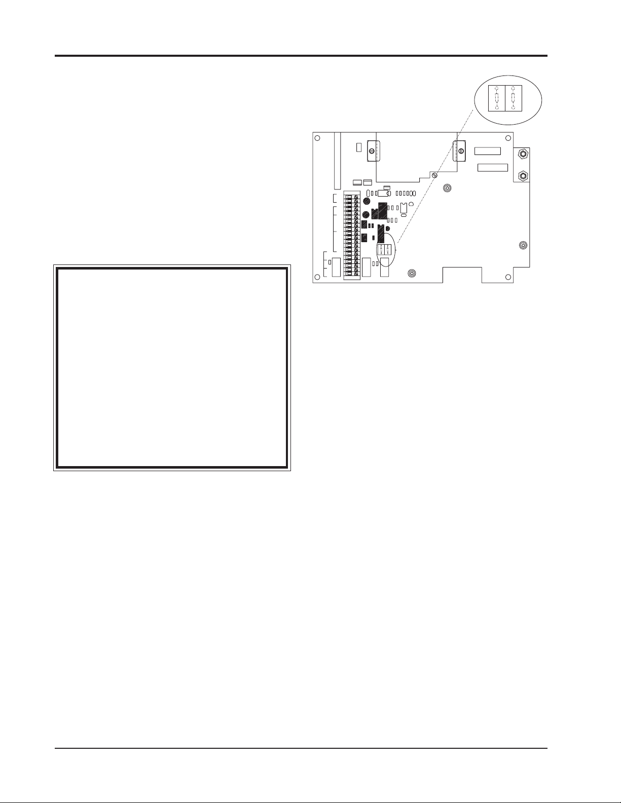
2.7.2 PROCEDURE. Remove main power from
RIS System: then set ON/OFF switch SW1 to OFF.
Follow the removal of the mechanical chassis from
Section 4.11.2.
Remove link (0 Ohm resistor) from the 4 - 20
tape gate with the lever and remove the old cassette, if installed. The cassette and its mounting
spigots are designed to fit tightly; use a firm and
direct pull to disengage the cassette. See Figure 1-2
for the location of the items referred to.
OUTPUT position using wire cutters to cut both
ends of the link. Solder buss wire link into the 0-1
Volt position per Figure 2-1.
Reinstall the mechanical chassis, cables, and
hoses using the first two paragraphs of Section
NOTE: Make sure that the ‘O’ ring
installed in the cassette molding, (and
which seals purge connections), is not left
behind when the cassette is removed.
4.11.5.
Page 2-4 Instruction 2772-0803
Page 19

REMOTE INTELLIGENT SENSOR - AREA MONITOR
If the ‘O’ ring is left on the purge spigot the
new cassette will not seat fully and faulty tape
handling will occur.
Push the new cassette firmly into position.
When doing so make sure that the tape enters the
open gate and does not catch on the side and break.
If the tape is not tight and in the correct
position to enter the gate, carefully tighten it by
turning the take up spool.
It is not necessary to touch the tape directly.
Touching the tape with bare fingers is undesirable
because of chemicals used to impregnate the tape.
When the cassette is in position, close the tape
gate and press the tape reset button to reset the
tape counter (to 99%) and initiate a new cycle.
NOTE: It is recommended that before
exiting TEST Mode, the System
Parameters are checked as described in
Section 2.8.2. The check takes a few
minutes and ensures that the system is in
optimum adjustment.
Exit the TEST Mode by pressing the red button
inside (on the door) again and close the door.
Tighten the door screws and take care not to over
tighten them. The above procedure is summarized
in the following:
Disable external alarms & warn staff.
Open door and enter TEST Mode.
Remove old cassette, check for retained ‘O’
ring.
Fit new cassette and close gate.
Press tape reset button & observe tape step.
Check system parameters.
Exit TEST Mode and close the door.
2.8.2 CHECK AND ADJUST SYSTEM
PARAMETERS. This procedure can be carried out
if a system fault is reported, as a routine check
after cassette replacement, or at any other time it
is necessary. The full sequence of data displayed in
the TEST Mode depends upon the options fitted to
the particular system. All tests are given below for
completeness.
The parameters that are normally checked at
cassette change are: V system voltage, mA the
current, Light Levels track 1 & 2, and Flow
Rate. The others are set values that do not change
unless the system is switched off.
Entering the TEST Mode. Open the RIS
door, having taken precautions against causing
unnecessary alarms, and enter the TEST Mode by
pressing the red button on the rear of the door.
Each of the TEST Mode displays remains for 3
seconds before stepping to the next parameter.
This cycling of data repeats continuously until
the HOLD/RELEASE key is pressed to hold a
displayed parameter; or the TEST Mode button is
again pressed to exit the mode; or five minutes
passes. After five minutes an automatic return to
the NORMAL mode occurs.
2.8.2.1 V, System Voltage. The first displayed data
is system voltage. This is the regulated voltage
derived from the nominal 12 VDC external supply at
the system interface. The displayed value should be
6.9 ± 0.1V.
If adjustment is required, first press the HOLD/
RELEASE key to hold the display. Adjust by turning
potentiometer VR1 located on the base board near
the system switch SW1 (NOTE: See Supplement A
for older version PCB's). When adjusting, do so
cautiously and allow time for the battery voltage to
settle to the new value. Recheck the voltage 10
minutes after adjustment.
2.8.2.2 mA, ‘Charger Current’. This display shows
the system current taken under the test conditions.
Pump current is not included because the pump is
not running during this part of the test cycle.
The displayed current, in mA, is the total of that
taken by the system, (excluding pump), and the
battery charging current. A ‘normal’ reading is about
60-90 mA. This assumes a well charged battery and
an average specification system.
Note that if the system voltage is lower than
6.9 V, the charge current will be proportionately
higher. A mA reading that is much higher than the
range shown above suggests a discharged or faulty
battery if the system volts are correct.
2.8.2.3 Alarm Set Point. The numerical value in
ppb, or ppm, (system dependent) is shown with the
‘flashing bells’ icon. If the set point has not been
changed, the default value will be active. Default
values are shwon in Table #1.
To change the set point value, ‘hold’ display with
the HOLD/RELEASE key. At this point the least
significant digit will flash and it can be changed as
required by pressing the DIGIT key. Each press steps
one digit more. Press firmly.
When the first digit is selected, step to the next
higher decade by pressing the DECADE key. Again
use the DIGIT key to select the required number, and
so on. On completion, press the HOLD/RELEASE key
to allow the sequence of test data to continue.
2.8.2.4 Alarm Level 1 and 2. When the Relay alarm
option is fitted, there are two Alarm Levels and each
may be user adjusted. Both Alarm Level set ponts
are displayed in sequence when the option is fitted.
Instruction 2772-0803 Page 2-5
Page 20

REMOTE INTELLIGENT SENSOR - AREA MONITOR
Alarm Level 1 is displayed first and is identified by
the number 1 which is shown in addition to the
numerical set point value. Similarly, the Alarm level
2 set point which follows, is identified by a 2.
IMPORTANT: Be aware that if the RIS is
switched off at SW1, the alarm set point(s)
will be return to their default at system
switch on. It will therefore be necessary to
reestablish set points if they differ from the
default values.
2.8.2.5 Gas Curve. The gas curve for the system is
displayed as a number. Systems are fitted with an
alpha numeric display and the active gas curve
shown directly (e.g., MDI or TDI etc.). Most systems
have only one gas curve programmed in the software and that curve is permanently active.
2.8.2.6 Multi Gas Curve Systems. In special
‘multicurve’ systems, a curve can be selected by:
1. Pressing TEST switch to enter the TEST Mode.
2. Wait until the display scrolls to the gas curve.
3. Press HOLD key to freeze the display.
4. Press DIGIT key to select the required curve.
5. Exit the test mode.
NOTE: The ‘default’ curve is MDI and is
automatically selected at system power up.
Be aware that each system has its particular
Flow Rate as shown in Table #1. After track 1 flow
has been read, press the HOLD/RELEASE key to
‘release’ the display. Allow it to step to track 2 and
press the key again to ‘hold’ that reading.
Flow to both tracks is supplied by one pump and
switched to the active channel by solenoid valves.
The flow measured at each track should therefore
be similar. Adjustment to the pump flow is made
with the potentiometer located on the main board as
shown in Figure 1-2 and is described in Section 4.5.
2.8.2.9 Date & Time. If the Optional Printer card
is installed, the data displayed in the Test sequence
automatically includes the date and time. The date
and time are reset to zero, with any stored data
point information, when the system is switched off
at SW1. It is necessary to set the date & time when
the system is installed, and if it is switched off
subsequently.
'HOLD' Setting Date & Time. To set the date
and time, ‘hold’ the display and use the digit and
decade keys to select the required values. The
decade that flashes after the display is ‘held’ is
adjusted first in each case.
If the number required is stepped past, keep
going until the desired number comes round again.
Note that the date & time is not lost if the input
supply fails, providing the back-up battery is not
discharged and SW1 remains on.
2.8.2.7 Light Levels Track 1 & 2. The next
display in sequence, is track 1 light level value.
This is a numerical value between, approximately,
200 and 254. Also displayed is a separate 1 (for
track one). This is followed by the next display with
a similar reading and a 2 (for track two).
The ‘correct’ value for both light levels is 220.
However, variations occur normally because of
small changes in the reflective property of the tape
along its length. These variations do not normally
exceed ±2 or 3. If the light level reading is 220 ±2 or
3, do not adjust. If it is approaching 200, or more
than 235 it should it be reset to 220.
NOTE: The light level may vary slightly
tape to tape. It is essential that checking
and adjustment is only made with a tape
in the gate and the gate closed. See Section
4.4 for detailed instructions on adjustment.
2.8.2.8 Flow Rate. While the light level test cycles
are active, the pump is running and ‘sample Flow
Rate’ can be checked. This is done by HOLD-ing the
display at 1. (and afterwards at 2.), and measuring
Flow Rate with a suitable flow meter connected in
series with the sample inlet tube.
2.8.2.10 Interruption of TEST Mode Cycle. If
5 minutes have elapsed since entering the Test
Mode, the display will revert to “normal”. To
complete the adjustments, press TEST Mode switch
again to reenter the mode and carry on.
2.8.2.11 Completion of Checks. Exit the TEST
MODE by pressing the red TEST BUTTON again on
the rear of the door.
NOTE: It is occasionally possible to
initiate a display that contains both
‘normal’ and ‘test’ data simultaneously. If
this occurs when exiting the TEST Mode,
press red TEST MODE button to reenter
the mode and then again to exit it cleanly.
When installing a new tape, press the red TAPE
RESET button on the left of the tape gate to reset
the system and the tape counter.
Close the door and tighten the securing screw
fasteners. The display should now show: SYSTEM
OK and a zero NUMERICAL ppm/ppb value
(assuming monitored atmosphere is zero) alternating with 99% which indicates the cassette life
available. There should be no fault icons shown.
Page 2-6 Instruction 2772-0803
Page 21

REMOTE INTELLIGENT SENSOR - AREA MONITOR
2.9 OPTION PCB INSTALLATION
Under the cover on the main board are three
slots for mounting option boards. An option board
can be inserted in any available slot. The two
option cards available are the Serial Printer
Interface PCB, and the Alarm Relay PCB (See
Section 5.5 for order numbers).
2.9.1 PRINTER (OPTION) INTERFACE
INSTALLATION. A suitable external printer can
be connected when the printer option is fitted. This
is a ‘plugable’ option and may be added any time.
Section 3.14 explains the user selectable aspects.
The Printer option is a user installed feature
for which the external printer socket is pre-wired.
To install, proceed as follows:
The following parts are required: Printer PCB,
Portable Printer (See Chapter 5 for part numbers)
complete with charger and lead.
Refer to Sections 3.14.3 and 3.14.4 and set the
switches on the Printer board to select the desired
date format, printer interval and the baud rate.
When handling the option board wear a wrist strap
with the clip grounded at RIS common.
Disable external warning systems controlled
by the RIS to avoid unnecessary alarms.
Open the RIS door and switch off the system at
SW1. Before fitting the option board, wear a wrist
strap with the clip grounded at RIS common.
Terminal # 1 on J1 can be used.
If a wrist strap is not available, avoid touching
components on the option board and the main
board.
Slide the Printer option board into a slot and
engage the connectors. If the board is not put in
correctly, the connectors will not mate.
Set the date and time using the procedure in
Section 2.8.2.9.
Replace the cover on the main board, plug
printer into external socket provided, turn on the
printer, wait for the printer to print "Ready", and
check printer operation by pressing the PRINT key.
2.9.3 ALARM MODULE CONNECTION. The
GMD Alarm Module is available for connection
directly to an RIS’s interface terminals. Single or
multiple Alarm and RIS combinations are possible
and are described in the Alarm Module Manual
(2701-1982). Basic connection of an Alarm to an RIS
is shown in that manual.
2.9.4 RELAY ALARM INSTALLATION. To
install, follow the steps below:
Disable external warning systems controlled by
the RIS and route additional cabling for the extra
relay outputs that will be made available.
Open the RIS door and switch off the system at
SW1. Disconnect the single relay output wiring from
terminal strip J1 inside the RIS. Remove the black
main board cover on the door rear to expose the
option board slots.
Check that the two EPROM’s are Version 30-xx03 or higher, where xx is the gas curve code (e.g. 00
for TDI, 06 for MDI etc.). 03 at the end of the version
# confirms that the relays are normally closed in the
‘off' state and open on alarm.
Slide the Relay Alarm Option board into a slot
and engage the connectors. If the board is not put in
correctly, the connectors will not mate. When
handling the option board wear a wrist strap
with the clip grounded at RIS common. Termi-
nal # 1 on J1 can be used. If a wrist strap is not
available, avoid touching components on the option
board and the main board. Replace the cover on the
main board.
Bring the new interface wires into the system
and connect them according to the Figure 2-2.
Ensure correct polarity is observed. Switch the
system on at SW1 and check for correct operation of
the externally connected alarm system/s.
The gas alarms can be checked with the use of a
Test Card, (see Section 3.13.3), or by opening the
tape gate with the system operating.
2.9.2 PORTABLE PRINTER. This printer is
supplied complete with internal battery, charger
and interconnecting cable. A fully charged printer
battery allows for printing a complete 7 days worth
of data. The printer can also be used ‘on line’ via
the supplied charger. See Section 3.14 for printer
operation.
Instruction 2772-0803 Page 2-7
Page 22

REMOTE INTELLIGENT SENSOR - AREA MONITOR
TERMINAL USE AND TERMISILKSCREEN IDENTS NAL
12 VDC – 1
INPUT + 2
(Connected internally to #1) 3
ANALOG – A 0V 4
OUTPUT + A OP 5
NET- A IN 6
WORK A OUT 7
COMMS B 8
INTERFACE S 9
PI 10
SERIAL PO 11 DATA Non GMD
PRINTER PRDY 12 BUSY Printer
INTERFACE PPRS 13 GROUND see Sec. 3.14
0V 14
COMBINED GAS RLA1 + 15 + Fault/Alarm
& FAULT ALARM GAS ALARM 1 – 16 RLA1 O/P or Relay O/P
NOT RLF +17+
ACTIVE FAULT ALARM – 18 RLF O/P
NOT RLA2 +19+
ACTIVE GAS ALARM – 20 RLA2 O/P
s s
RELAY ACTION RELAY ACTION
WITHOUT WITH
2701-1761 2701-1761
OPTION CARD OPTION CARD
INSTALLED INSTALLED
GMD PRINTER: When purchased as an option, the
printer is usually plugged into the pre-wired external socket provided. Alternatively it can be hardwired into the system through the J1 interface using
the information provided in Section 3.14 of this
manual.
RELAY OUTPUTS: Observe polarity. The
outputs present a closed circuit that opens
on fault or alarm.
With a single combined output, the ‘relay’
toggles position on fault and remains open
on alarm. Adding the optional three-relay
board option enables the three-relay
option.
CONNECT CABLE
SCREEN(S) ONE
END ONLY
To 12 VDC
+PSU
CURRENT RIS J1 INTERFACE CONNECTIONS WITH
SYSTEMS USING VERSION 30-XX-03 AND HIGHER
SOFTWARE.
Figure 2-2. Hookup for Phase 2 Base Board Terminal Strip
Page 2-8 Instruction 2772-0803
Page 23

REMOTE INTELLIGENT SENSOR - AREA MONITOR
Figure 2-3. Phase 2 Base Board Terminal Strips
Instruction 2772-0803 Page 2-9
Page 24

REMOTE INTELLIGENT SENSOR - AREA MONITOR
Figure 2-4. Figure 2-5.
Page 2-10 Instruction 2772-0803
Page 25

REMOTE INTELLIGENT SENSOR - AREA MONITOR
Figure 2-6.
Instruction 2772-0803 Page 2-11
Page 26

REMOTE INTELLIGENT SENSOR - AREA MONITOR
Figure 2-7 Figure 2-8
Page 2-12 Instruction 2772-0803
Page 27
REMOTE INTELLIGENT SENSOR - AREA MONITOR
K
3 SYSTEM OPERATION
AND FEATURES
3.1 COMPLETE SAMPLING
SEQUENCE
The sequence starts with system and cassette being
purged before gas sampling starts. In addition, a
reference light level reading is taken from the fresh
tape spot under the optics block.
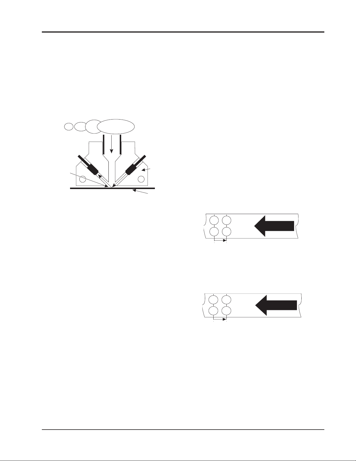
INCOMING
SAMPLE
PHOTO
DIODE
LIGHT
REFLECTED
OFF TAPE
SURFACE
Figure 3-1. Sampling Sequence
During the sampling period the tape spot is
scanned every two seconds. This frequent scanning
detects the change in the reflected light value that
occurs if a stain develops.
If no stain, or a low density stain, is detected,
sampling continues for a fixed four minutes. At the
end of this time calculated concentration for that
cycle is displayed and the next cycle starts.
The development of a significant stain shortens
the sampling cycle and the concentration value is
displayed immediately, as described in more detail
below.
When a concentration above alarm set point is
detected, the gas alarm relay/s opens to initiate
external alarm systems and warning devices. This
is in addition to the visual warning display.
3.1.1 AUTOMATIC PURGE CYCLE. A purge
sequence occurs after every tape step. The pump
runs at a higher Flow Rate for 10 seconds; air
inside the tape cassette, and the enclosure, is
exchanged for filtered air. The incoming air is
filtered as it passes through a ‘scrubber’ filter in
the cassette. This is shown in the diagram in
Figure 2-8.
Purging prevents the build up of gas in the
system, and in the cassette where it could preexpose the tape. The ‘scrubber’ filter is automatically renewed at each cassette change.
LIGHT
EMITTING
DIODE
TAPE
OPTIC
BLOC
Effective purging requires the enclosure to be
properly sealed. Ensure that the cable glands and
the door are air tight. Unused cable glands can be
tightened onto a short piece of cable.
Purge inlet and exhaust ports can be piped to a
remote location, where this is necessary.
3.1.2 TWIN TRACK TAPE SAMPLING. At
start-up the incoming sample is passed through the
lower tape half (track 1). When that sampling period
is complete, the microprocessor decides if a stain has
formed on the tape. If not, the next sample is again
passed through the same spot on track 1. Conversely
if a stain was formed, the second sample is switched
to pass through the upper half (track 2). The same
sequence occurs at the end of that sample period and
track 2 is reused if no stain is detected.
At this point the tape is stepped on and the next
sample passed through the next track 1 spot. Figure
3-2 shows the sequence where no stain develops and
the maximum of four sample periods occurs before
the tape is stepped.
3/4 7/8
1/2 5/6
STEP
4 SAMPLE PERIODS OF 4 MINUTES EACH
= 16 MINUTES PER TAPE STEP
TRACK 2
TRACK 1
TAPE
Figure 3-2. No Stain, Both Tracks Used Twice
Figure 3-3 shows that only two sample periods
per tape step occur if significant stains develop on
the tape.
2 4
1 3
STEP
2 SAMPLE PERIODS PER STEP. EACH SAMPLE
PERIOD IS A MAX OF 4 MINUTES, OR LESS IF
THE STAIN IS SIGNIFICANT = 8 MINUTES PER
TAPE STEP
TRACK 2
TRACK 1
TAPE
Figure 3-3. Stain On Tape, Both Tracks Used Once
3.1.3 TAPE REFERENCE MEASUREMENT. At
the start of each sample period, the tape spot being
used is scanned by the light pulse (generated by the
optics system), see Figure 3-1. The value of the
reflected light is measured and stored as the reference against which the light value, during and at the
end of the sample period, is assessed..
Instruction 2772-0803 Page 3-1
Page 28

REMOTE INTELLIGENT SENSOR - AREA MONITOR
This method eliminates the ‘zero drift’ that
could otherwise occur with slight variation in the
reflective value of the tape. It also ensures that
system accuracy is not compromised when reusing
the same tape spot. System accuracy is not compromised when reusing the same tape spot.
3.2 DENSITY & TIME OPERATING
MODES
Actual sampling takes place under control of
one of two operating modes. The microprocessor
automatically selects the appropriate mode in
relation to the dynamic situation being monitored.
The two modes are:
3.2.1 DENSITY MODE. This operating mode is
used when the sampled concentration is below a
predetermined threshold. Under this condition, the
gas sample period is a fixed four minutes.
During the four minutes, a sample is drawn
into the system at a specified Flow Rate. The
product of time and flow provides the measured
volume used in the subsequent calculation of
concentration.
The term ‘Density Mode’ is used because the
sample volume is fixed and the variable used in the
concentration calculation is stain density.
3.2.2 TIME MODE. When the concentration level of
the sampled gas exceeds the preset threshold value,
the stain on the tape develops quicker. By measuring
the time it takes to reach the threshold density, it is
possible to calculate the sample concentration.
Using the ‘time mode’ provides real benefits; a
reading and an attendant alarm are provided rapidly
when concentrations are high, and the tape is never
allowed to become saturated. Because the tape doesn’t
saturate, the reaction is always in the linear region
where the monitor’s accuracy is maximized.
An additional benefit is that the tape continues to
act as a filter and prevents the sample getting past
the optics block and contaminating the system
beyond.
3.3 CHANGE-OVER FROM DENSITY
TO TIME MODE
With a 1,000 ppb instrument, the change-over
from density to time mode occurs at 20 ppb. Other
range instruments have change-over points in
proportion. This dynamic control of sampling mode is
automatic.
3.4 MINIMUM SAMPLE TIME
The minimum sample time in the time mode is
approximately 16 seconds. This reponse occurs when
the monitored concentration has reached, or exceeded, the maximum range of the instrument.
3.5 TAPE CASSETTE LIFE
The cassette has a nominal life of 30 days.
However the rate at which the system uses tape,
and the consequent cassette life is dependenty
mainly on the gas concentration monitored.
If the level is zero, or very low, a tape step will
occur every 16 minutes (4 x four minutes). This is
because the two tracks are each used for two
consecutive samples of four minutes as explained in
Section 3.1.2.
If the monitored concentration is higher, the
tape steps every two sample periods; also the
sample period itself can reduce below 4 minutes
(dependent upon the concentration reached). A tape
step will therefore occur at least every 8 minutes (2
x 4 minute sample periods) and more quickly if
levels are high.
Infrequent high gas concentrations will not have
much effect on cassette life, but if monitored levels
are continuously significant, cassette life will be
noticeably reduced.
In most applications, since monitoring is being
done to confirm an expected zero, or very low gas
concentration, cassette life will be close to the
30-day period specified.
3.6 DATA POINT STORAGE
At the end of each sample interval the calculated data point is stored, as are the calculated
TWA’s. The 15 minute TWA , and the 8 hour TWA
are both available for immediate display at a touch
of the appropriate front panel key switch. The
stored data points can be printed out as a record
when the optional Printer option is fitted.
3.7 SYSTEM DISPLAY
The displayed information, including symbols,
or icons, depends upon the operating conditions.
These and related information are as described below.
3.7.1 SYSTEM NORMAL, GAS CONCENTRATION ZERO OR LOW. This is the usual operating
condition and three pieces of information are displayed.
Page 3-2 Instruction 2772-0803
Page 29

REMOTE INTELLIGENT SENSOR - AREA MONITOR
SYSTEM OK icon confirms the system is
operating normally.
NUMERICAL VALUE (in ppb or ppm)
alternates with % value of remaining cassette
life. When cassette is new the display reads
99%. As the tape is used, the numerical value
reduces in proportion.
NOTE: If the system is turned off and then
on at SW1, or if the tape reset button is
used, the tape counter is reset to 99%. This
occurs despite the actual tape remaining.
3.7.2 SYSTEM NORMAL, GAS CONCENTRATION ABOVE THE ALARM THRESHOLD.
Besides the SYSTEM OK and the NUMERICAL
VALUE of the measured concentration, a ‘FLASHING BELLS’ icon is shown across the top of the
display. This provides a strong visual warning that
a Gas Alarm is present. The display is maintained
during the period that the threshold level is exceeded and until a complete sample period has
passed where the concentration falls below the alarm
level.
3.7.3 OVER RANGE ALARM. When the monitored concentration exceed the system range, the
‘flashing bells’ icon is accompanied by the numerical
readout displaying 9999 (ppb models) or 99.99 (ppm
models).
3.7.4 SYSTEM FAULT. When self diagnostics
detect a fault condition, the SYSTEM OK icon is
turned off and one or more fault icons are displayed. Icons and their meaning are as follows:
Constant
This symbol shows that the input supply
has failed, or is not connected, and the
system is operating from the internal
back-up battery.
Flashing
Shows that the back-up battery charge is
low. This could occur with long interruption
of input power. It can also warn that the
battery is not maintaining an adequate
charge during NORMAL operation.
Constant
Warns that the cassette has run out of
tape, or the tape has broken, or the tape
gate has been left open.
Flashing
This symbol shows that sampling vacuum
has dropped. The cause could be a pump
failure or an air leak.
Optics
Icon warns that the light level is not
acceptable. In addition, the affected
channel is shown by a 1 or 2, or both.
NOTE: This will occur if the tape gate is
opened, an external light source enters the
sampling input FET tube(s), the tape breaks,
runs out, or, if the cassette is changed
without first going into the TEST Mode.
Door Open
This icon is displayed when the system door
is open. It is also shown if the ‘door closed
switch is incorrectly adjusted or if the door
securing screws are not tight, be careful
not to over tighten them! The switch
adjustment procedure is detailed in Section 4.7.
3.8 SYSTEM ALARMS
The standard RIS provides displays of gas and
fault alarms, and a combined ‘relay’ output. Basic
systems have one gas alarm set point with a default
value established by the system software. The alarm
set point is also user adjustable through the RIS
keyboard so that it can be set to an appropriate local
value. Set point adjustment is covered in Section
2.8.2.3. The default values are shown in the Table #1.
A fault alarm is initiated by any one of several
monitored parameters. Appropriate icons are shown
on the display when a fault is detected.
3.8.1 GAS ALARM. When a gas concentration
value above the alarm set point is detected, the
‘flashing bells’ icon provides visual warning. Simultaneously the combined gas alarm/fault relay opens.
Both warnings, visual and relay signal, remains
active until a gas concentration lower than the set
point is measured over a complete sampling cycle
(normally 4 min.). This ensures that small variations around the set point do not cause intermittent
alarm operation.
3.8.3 ADDITIONAL GAS ALARM SET POINT.
When the Relay alarm Option is installed, a second
alarm level set point is provided. This second set
point is also user adjustable. In this case there are
three active relays, one for each alarm level, and one
for fault indication.
Instruction 2772-0803 Page 3-3
Page 30

REMOTE INTELLIGENT SENSOR - AREA MONITOR
3.8.3 FAULT RELAY. With the basic system
the single (combined) gas alarm/fault relay is
operated to provide external warning of any of the
monitored ‘fault’ conditions. In a fault condition, the
relay output ‘toggles’ open and closed at 1 Hz. When
the Relay alarm Option is fitted, a separate relay
output is provided which opens and remains open
when a fault is detected. The fault icon and the
relay output remain active until the fault condition
is cleared.
3.9 DIAGNOSTICS
Key system parameters are constantly monitored during normal operation. If any parameters
fall outside acceptable values, a system fault
condition is initiated and the appropriate display
and relay output warnings are given. Each monitored condition, and the icon used on the display in
warning, is detailed in Section 3.7.
3.10 TEST MODE
The TEST Mode is provided to allow users to
quickly check key system parameters. This helps to
ensure the system is always operating in optimum,
trouble-free conditions.
It is recommended that the system parameters
are checked, and recorded, at each cassette change.
Section 2.8.2 explains this and how to use the TEST
Mode. A record sheet is included at the end of the
manual.
TEST Mode. The switch is used to select the
required decade when setting programmable
values (For instance, when changing the alarm
level/s or setting the date/time with the
printer option fitted).
3.11.4 ‘8 HR TWA (DIGIT SET)’ key. Again the
function depends upon the operating mode.
Normal Mode. Pressing the key initiates the
TWA display for the preceding 8 hours.
TEST Mode. The key is used, together with
the decade select key, to select required digit.
3.12 USING THE KEYBOARD
The switches used in the keyboard are of a
rugged sealed membrane type. To ensure positive
operation of the key switches, press firmly.
3.13 OPTIONAL FEATURES
Several optional features are available to extend
the capability of the standard RIS. These options
are:
3.13.1 RELAY ALARM OPTION. This can be
user-retrofitted. The option provides two separate
alarm relay outputs. Each has a user-adjustable set
point. In addition, a separate fault relay is provided. The option is available for all current RIS
systems with phase 2 base boards and requires the
fitting of an additional circuit board in an already
provided slot.
3.11 KEYPAD FUNCTION
Use of four keys, and the mode in which each is
active, is as follows:
3.11.1 ‘HOLD/RELEASE’ KEY. This is a toggle.
It is used to hold the displayed data/function for
observation or adjustment. The display ‘holds’ for 5
minutes unless released by a second key press. This
key operates in both Normal and TEST Mode.
3.11.2 ‘PRINT' KEY. This has two functions.
Normal Mode. The key is pressed to download
the data stored in the (optional) printer card
memory to the printer.
TEST Mode. The key is used to clear the
printer card memory (if one is fitted).
3.11.3 ‘15 MIN TWA (DECADE)’ KEY. There are
two functions:
Normal Mode. Operation of the key displays
the TWA for the preceding 15 minutes, (or 10
minutes, if this option is applicable).
3.13.2 PRINTER INTERFACE OPTION. Can be
user-retrofitted. The option provides data storage for
up to 7 days of data points, a clock function and
printer control circuitry. When this option board is
fitted, an external printer can be plugged into the
pre-wired port; or hard wired to the system interface.
Option board is fitted into an already provided slot.
The printer circuit board is fitted with DIP
switches to allow selection of the interval at which
data points are printed. Each data point can be
printed as it is calculated, or at intervals from 30
minutes to 24 hours. Printing ‘on demand’, whenever the RIS control panel PRINTER key is
pressed is also available.
In addition to the time and value of data
points, a header is printed with TWA’s, system
current and voltage.
3.13.3 TEST CARD. The following shows how to
simulate a gas alarm and enable the operation of
external alarm systems to be checked.
Page 3-4 Instruction 2772-0803
Page 31
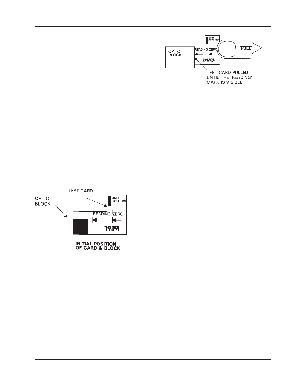
REMOTE INTELLIGENT SENSOR - AREA MONITOR
IMPORTANT: Please note that this
method is not suitable for, and is not
intended to be used for, checking or
verifying the system’s calibration, but only
for alarm simulation and checks.
Test Preparation. Warn that tests are to be
carried out and that external alarm systems may be
activated. Check that the RIS is powered up and
working. Open the door and disable the door open
switch with a magnet. (A suitable magnet is
available, see Chapter 5). It may be convenient in
some cases to remove the board cover.
Enter TEST Mode (press the Red button on
the main board), open the tape gate and remove the
cassette. Insert the Test Card in the gate with the
zero line on the card lined up with the edge of the
optics block. See Figure 3-4. Close the gate.
NOTE: Due to the reflectance difference
between the cassette tape and the Test
Card, it may be necessary to readjust the
light level of track 1 to 220 with the Test
Card installed in the tape gate. Refer to
Section 4.4 (Adjusting Light Levels) for
instructions. It is not necessary to adjust
track 2 for this test.
Figure 3-5. Pulling Test Card
This puts the dark ‘stained’ section of the card
under the photo cell. The result should be an immediate ‘gas concentration’ of, typically, 40 to 60% of
full range shown on the display (i.e. approximately
400 to 600 ppb for a 1,000 ppb RIS).
NOTE: The actual reading is not important
if it is above alarm set point.
If the 20 seconds is reduced, the concentration reading will be higher. Conversely if it is
increased the concentration will be lower.
NOTE: Be aware that a fault alarm will,
usually, inhibit a gas alarm; make sure
that there isn’t a fault condition active
when test is started.
Figure 3-4. Installing Test Card
Exit TEST Mode, leaving test card in gate.
Carrying out the Test. Press the Tape Reset
button (the red button on the left of the optics
block). The tape advance cam will turn (but will not
move the test card), and a cycle commences. The
purge cycle will start, listen for the cycle to end
10 seconds after it starts, (the pump sound will
reduce as the pump slows). Start Counting when
the purge cycle stops and the normal sampling cycle
starts. After 20 seconds pull test card to the
right so that the READING mark is lined up with
the right side of the block, Figure 3-5.
The test card check can be repeated by opening
the gate, repositioning the test card, pressing the
tape reset button and starting again.
IMPORTANT: AFTER CHECKS have
been completed, enter the TEST Mode,
remove the test card, and replace the
cassette. Reset the light level of track 1 to
220 if changed. Remove the magnet used to
inhibit the door open alarm and replace the
cover on the main board, (if this was
removed). Put the RIS back into service.
3.14. PRINTER OPERATION & USE
(OPTIONAL FEATURE)
3.14.1 GENERAL. The Printer option requires
fitting of the Printer Option board and connection of
a suitable Printer. See Chapter 5 for part numbers.
Installation of Printer Option board is described
in Section 2.9.1. Methods of connecting a suitable
printer are described below.
Instruction 2772-0803 Page 3-5
Page 32
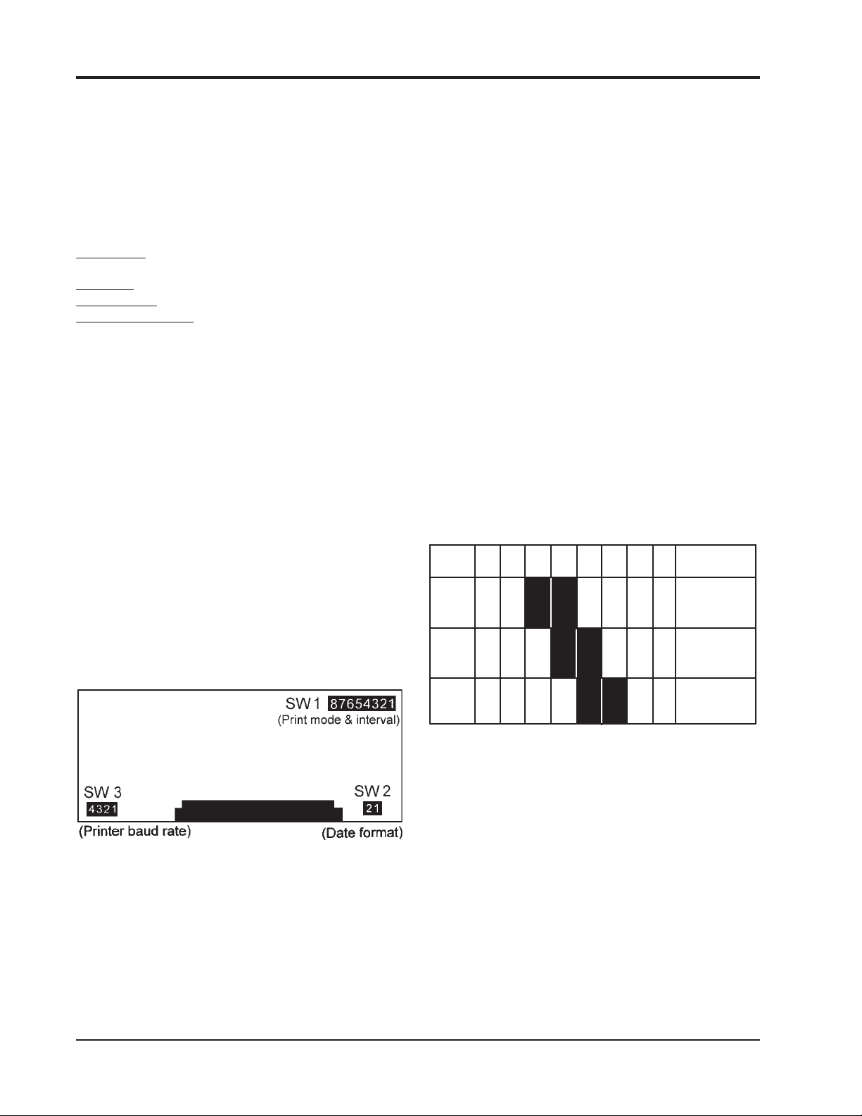
REMOTE INTELLIGENT SENSOR - AREA MONITOR
In addition to that supplied by GMD, printers
meeting the specification detailed below may be
used. Those intending to use an alternative printer
should check the specification carefully.
3.14.2 PRINTER SPECIFICATION. The
printer must be capable of receiving serial data and
meet the following requirements:
Baud Rate: 600, 1200, 2400, or 9600
bits/sec.
Stop Bits: 2 bits
Word length: 8 bits Parity:
Even Signal Level: TTL Logic Type: Positive
3.14.3 PRINTOUT MODES. Three modes of
printer operation are provided. They are:
Print ‘On Line’. In this mode each data point
is automatically printed as it is generated.
Print at Intervals. The data is stored and
printed out at predetermined intervals. The
interval is user selected.
Print on Command. Data points are stored
until the PRINT key is pressed. Up to 7 day’s
worth of data can be stored for print out when
commanded.
In each of the above printer modes, the storage
is cleared when the data is printed out.
If necessary, printer storage can be cleared at
any time as described in Section 4.9.
3.14.3.1 Printing ‘On Line’ (printing every data
point as it is calculated). Select by setting:
Switch # 1 of SW1 switch bank on the Printer
Module to ‘OFF’ and set switches 2 to 8 to ‘ON’.
See Figure 3-6 for switch location.
Where it occurs, gas alarm, or type of fault
detected, is printed out next to the time and concentration.
3.14.3.2 Print at Intervals. Select by setting:
Switch # 1 of SW1 switch bank on the
Printer Module to ‘ON’. See Figure 3-6 for switch
location.
Printing intervals are available in 30 minute
increments up to 24 hours. Intervals are set with
SW1 switches # 3 to # 8, as follows.
Switch # 3 to # 8 each enable a discrete period of
time when turned ‘OFF’. Each enabled switch adds
its time value to achieve the total required. The
value of each switch when ‘OFF’ is:
Switch # 8 = 30 minutes
Switch # 7 = 1 hour
Switch # 6 = 2 hours
Switch # 5 = 4 hours
Switch # 4 = 8 hours
Switch # 3 = 16 hours
Switch # 2 is not used and is left ‘ON
Examples: For print intervals of 6, 12 and 24
hours, SW1 switches would be set as follows:
SW1 #8 #7 #6 #5 #4 #3 #1 TOTAL
on on off off on on on
Time 0 0 2 4 0 0 -- = 6 hour
on on on off off on on
Time 0 0 0 4 8 0 -- = 12 hour
on on on on off off on
Time 0 0 0 0 816 -- = 24 hour
Any combination of the switches can be used to
select an interval up to 24 hours.
Printout: A full printout of all measured
parameters occurs at each interval.
3.14.3.3 Print on Command. Select by setting:
All switches ( # 1 to # 8) of SW1 switch bank
on the Printer Module to ‘ON’. See Figure 3-6 for
Figure 3-6. Switches 2 & 3
Initial printout in this mode includes: date,
time, tape left %, battery volts, battery charge
(total system current in mA), alarm level and the
monitored gas concentration. Also shown are gas or
fault alarms, if these occur.
Subsequent printouts show only the time
and concentration, unless there is a system fault or
an alarm present.
switch location.
The printout is initiated when the PRINT key on
the RIS front panel is pressed. The entire stored
data points are printed out.
Data is not lost if the PRINT key is inadvertently pressed without a printer connected.
Printout: A full printout of all measured
parameters occurs at each printing occurrence.
Page 3-6 Instruction 2772-0803
Page 33

REMOTE INTELLIGENT SENSOR - AREA MONITOR
3.14.3.4 Printed Date Format. A choice of month/
day or day/month format is available:
For the US month/day/year format, set SW2
switches 1 and 2 ‘ON’.
For the European day/month/year format, set
SW2 switches 1 and 2 ‘OFF’.
3.14.3.5 Data Storage Up To 7 Days. In any of
the selected modes, data can be stored for later
printout (up to 7 days of data). This is simply
achieved by unplugging the printer connector at the
RIS printer socket. When a printout is required,
plug in the printer connector, switch the printer on
and then press the PRINT key on the RIS front
panel.
3.14.3.6 Preventing Data Loss.
if a printer is connected to the RIS but not
Switched on. Under these conditions, the RIS
attempts to ‘dump’ data at the selected interval and
clears the data memory, even though no physical
printout is produced due to the printer being
switched off. To prevent this from occurring,
whenever the printer is not in use, always disconnect it, by its connector, at the RIS.
Data will be lost
This makes the microprocessor aware that a
printer is connected. The microprocessor then writes
each data point to memory locations on the board.
Once stored, the data is retained until it is
printed out, or deleted to make way for current data,
or when cleared under keyboard control.
Data is transferred at a higher rate than the
printer is able to print. Flow of data is therefore
controlled by the printer ready line (PRDY) which
changes state to enable, stop, or transfer as required.
3.14.4.4 Selection of Printer Baud Rate. The
Bacharach Printer has a baud rate of 600 bits/sec.
and printer option board has SW3 switches set with
switch # 4 ‘ON’ and the other 3 switches ‘OFF’.
The settings for the complete baud rate selection
are:
BAUD SW # 4 SW # 3 SW # 2 SW # 1
600 ON OFF OFF OFF
1,200 OFF ON OFF OFF
2,400 OFF OFF ON OFF
9,600 OFF OFF OFF ON
3.14.4 PRINTER CARD DESCRIPTION. In
addition to the switch functions already described,
the printer card provides the following function and
facilities.
3.14.4.1 Real Time Clock. Enables data to be
stored with relevant time and date reference. The
clock is not separately supported and if the system
switch SW1 is turned off it must be reset after the
switch is turned on.
The clock is set by use of the front panel key
switches, using the procedure described in Section
2.8.2.9.
3.14.4.2 Data Storage. Capacity for storing up to
7 day’s worth of data points is provided. The stored
data always contains the most recent record. When
full, the oldest data points are deleted allowing
space for the new data. Once the printer card is
installed, the storage of data takes place automatically.
When the stored data has been printed under
preset timed control, or a PRINT command from
the keyboard, the microprocessor clears the stored
data. The storage can also be cleared at any time by
using the procedure in Section 4.9.
3.14.4.3 Data Communication. The printer
interface card communicates with the microprocessor through a data buffer. Connecting a printer to
the printer port completes a circuit that links the
printer present line (PPRS) to ground (0 V).
3.14.5 CONNECTING A PRINTER. A printer can
be connected permanently, or plugged in when
required. In the latter case, one printer can be used
to support a number of RIS systems.
3.14.5.1 GMD Printer Connection. The GMD
printer is supplied complete with an interconnecting
lead that enables the printer to be plugged into the
standard, pre-wired, socket provided on the left side
of the RIS.
If required, the printer can be permanently
wired to the RIS interface by removing the plug from
the cable and connecting it into the J1 interface in
accordance with the information provided in the
table below.
Printer Cable Connect to J1 Signal
Wire Color Terminal # Identification
Not used 10 PI
WHITE 11 PO
RED 12 PRDY
BLACK 13 PPRS
BLACK 14 0 V
First, turn off the RIS at the system power switch
SW1. Then feed the cable into the RIS through a
convenient cable gland. Carefully tighten the gland
around the cable to preserve enclosure sealing.
Instruction 2772-0803 Page 3-7
Page 34
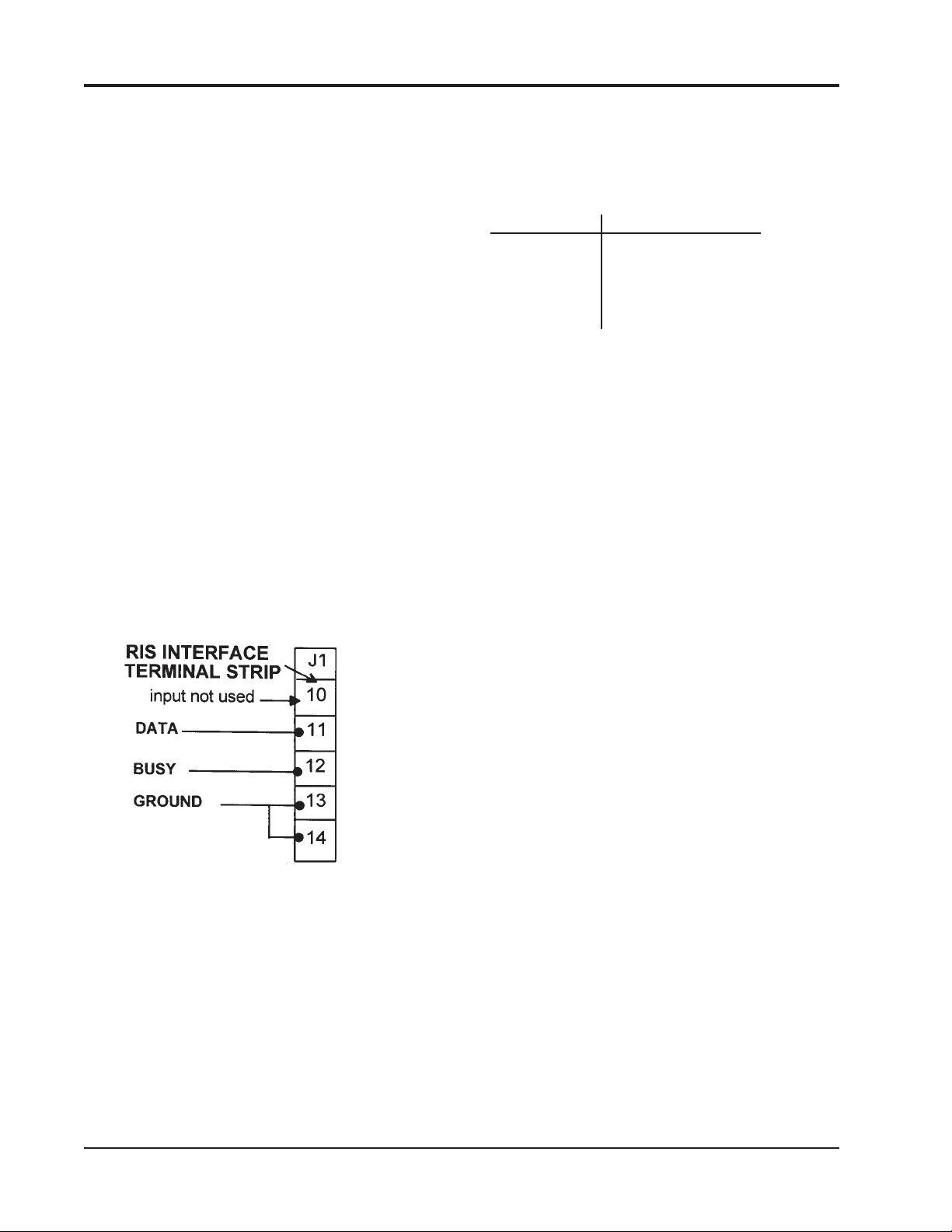
REMOTE INTELLIGENT SENSOR - AREA MONITOR
After the cable has been connected and checked,
switch the system back on and test the printer
operation. This is most conveniently done by setting
the # 1 switch on SW1 of the printer option board to
‘OFF’. This will cause each data point to be printed
as it is stored.
3.14.5.2 Connecting a Non-GMD Printer. First
verify that the printer meets the specification
detailed in Section 3.14.2.
Check the printer manual and identify the wire
color, or pin number, on the printer cable that
corresponds to BUSY, DATA and GROUND. If
only the pin numbers are given, open the plug on
the end of the printer cable and write down the wire
color that corresponds. The plug can then be cut off
and the wire ends prepared for connection to the
RIS interface J1. Cut off any unused wires in the
printer cable.
After turning off the RIS power switch SW1,
feed the cable through a cable gland and connect
the prepared printer cable as in Figure 3-7.
If the printer cable is screened, ensure that the
screen is grounded at one end only.
When connections have been made and
checked, tighten the cable gland, turn the system
on at SW1 and test the print operation.
The plug can then be cut off and the wire ends
prepared for termination in a plug that will mate
with that fitted on the RIS.
The plug should be connected in accordance with
the following table.
Plug Pin # Connect to:
1 to 3 No connection
4 DATA
5 BUSY
6 GROUND
7 Link to pin 6
If the printer cable is screened, ensure that the
screen is grounded at one end only.
When connections have been made and checked,
plug the printer into the RIS and check operation.
Refer to Section 3.16.3 for details of the available
printout modes.
Figure 3-7 Non-Bacharach Printer Interface
3.14.5.3 Portable Use of a Non-GMD Printer.
First verify that the printer meets the specification
detailed in Section 3.14.2.
Check the printer manual and identify the wire
color, or pin number, on the printer cable that
correspond to BUSY, DATA and GROUND. If
only the pin numbers are given, open the plug on
the end of the printer cable and write down the wire
color that corresponds.
Page 3-8 Instruction 2772-0803
Page 35

REMOTE INTELLIGENT SENSOR - AREA MONITOR
4 MAINTENANCE AND
TROUBLESHOOTING
4.1 MAINTENANCE GENERAL
Under normal circumstances, recommended
routine maintenance consists of cleaning the
exterior of the enclosure, carrying out a check of
key parameters, and checking certain parts for
mechanical tightness. In addition, occasional
cleaning of the input path and optics block may be
required under adverse sampling conditions. Each
of these procedures is dealt with below.
NOTE: Most procedures require the unit
to be in TEST Mode. To enter TEST Mode
see Section 2.8.2.
4.2 VERIFYING THAT A GAS ALARM
WAS CAUSED BY GAS
In situations where the gas level monitored is
continuously zero and an alarm occurs, there may
be a tendency to assume that a system ‘fault’ is
responsible. Under these circumstances first
assume the alarm is genuine and take appropriate
action. The presence of gas is easily verified.
Put the system into the TEST Mode and
remove the cassette. Examine the tape in the gate
area and toward the take up spool. The presence of
a circular stain, or succession of stains, will verify
that gas has been sampled. The nature of the stains
will show the level of exposure as follows:
A faint stain, or succession of faint stains
increasing in density, suggests an initially low
concentration that is slowly increasing. As monitoring continued, the stain density would diminish as
the contamination dispersed.
If the stains are intense, or become so quickly,
and then remain at the same high density, a
significant concentration has been sampled. (The
constant, dense stains, show that the system was
operating in the ‘time mode’ which only occurs at
higher concentrations. See Section 3.2.2).
4.3 CLEARING A SPURIOUS ALARM
Allow the Test data to cycle to the light level
value (track 1), HOLD the display and check that
the reading is near 220. RELEASE the track 1
display and then HOLD to check track 2. RELEASE
track 2 and again press the TEST Mode button to
return to the NORMAL mode.
The light fault will now be clear and the only
fault icon displayed should be the ‘door open’ symbol.
The ‘Flashing Bells’ and the numeric display will
remain until the end of the current four minute
sampling period (which commenced on the exit from
the TEST Mode).
4.4 ADJUSTING LIGHT LEVELS
RIS’s manufactured before April 1992 have
adjustment potentiometers under the tape cassette
which has to be removed before light levels can be
adjusted (see Supplement A ). This is not necessary
for the adjustment on units made after April ’92,
which is shown below:
Install the tape cassette if not present. Light
levels can only be adjusted with the cassette installed.
Enter the TEST Mode by pressing the red button
on the back of the door. Wait until the display has
cycled to show:
200 to 254
1
Press the HOLD/RELEASE
button on the front panel
200 to 254
firmly so that the display
shows:
1
HOLD
Figure 4-1. Entering TEST Mode
This display status will be maintained for
5 minutes, or until the HOLD/RELEASE button is
pressed again.
Adjustment is made by means of the two potentiometers that are located beside the tape head and
accessed through holes in the top plate. The light
level track 1 is adjusted by one, and track 2 by the
other. The potentiometer access holes in Figure 4-2.
If the tape gate is opened without putting the
system into the TEST Mode, an ‘alarm’ may be
initiated. It is also likely that a ‘light fault’ will
occur. To clear these conditions:
Open the door (if it had been closed), and enter
the TEST Mode. Ensure that there is a cassette
mounted and that tape is in the gate which should
be closed.
Figure 4-2. Light Level Access Holes
Instruction 2772-0803 Page 4-1
Page 36

REMOTE INTELLIGENT SENSOR - AREA MONITOR
With the tape in place, adjust the track 1
potentiometer until the reading is 220. Clockwise
rotation of potentiometers increases the level.
When track 1 has been adjusted, press the
HOLD/RELEASE button to allow track 2 to be
displayed. HOLD this display as before and adjust
track 2 in the same manor as track 1.
After adjustments exit the TEST Mode by
pressing the red button on the rear of the door
again, unless other tests have to be done.
Exit the TEST Mode by pressing the red button
on the rear of the door again, unless other tests
have to be done.
4.5 CHECKING AND ADJUSTING
SYSTEM FLOW RATE
REFER to Table #1 to check the correct Flow
Rate for your system.
Connect a suitable flow meter in series with the
RIS input tube as shown in Figure 4-3. A bubble
meter or a rotameter (flow meter) with an accuracy
of ± 5% FSD is recommended. Ensure that the flow
meter is vertical or the subsequent reading will not
be accurate. Connection to the RIS input tube must
fit tight and not allow any leakage.
If there is a difference between the two track Flow
Rates of more than about ±5%, the difference should
be investigated and corrected.
NOTE: Porosity of the tape can vary a
little along the tape, and from tape to tape.
This factor may cause small changes in the
Flow Rate but the effect is not significant.
Don’t over-adjust this parameter.
Having set the correct Flow Rate, exit the TEST
Mode by pressing the red button.
4.6 DISABLING THE ‘DOOR OPEN’
ALARM
If the ‘door open’ fault alarm is inconvenient
when working with the door open, or it is necessary
to turn off the switch, it may be temporarily disabled as follows.
Hold a small magnet (see Section 5.5) close to
the semiconductor switch mounted in the bottom
left-hand corner of the main board. The polarity
must be correct, so if it doesn’t work the first time,
turn it around to reverse the polarity. Take care
not to damage the switch!
Figure 4-3. Flow Rate Hookup
Enter the TEST Mode and HOLD display at
Light Level 1 by pressing the HOLD/RELEASE
key. At this point the pump is running at NORMAL
sampling rate. Ensure there is tape in the gate, and
that the gate is closed. Take a reading of the track
1 flow and record it for reference.
If the flow is not at the specified rate, it should
be adjusted using the Flow Adjust POT which is
located on the main circuit board on the back of the
door (See the Figure 1-2 for the location). It is not
necessary to remove the protective cover over the
board to adjust this POT.
After the track 1 flow has been adjusted, press
the HOLD/RELEASE key. Allow the display to
cycle to track 2 and press the HOLD/RELEASE key
again to enable the track 2 flow to be checked.
Because the flow has already been adjusted on
track 1, the flow should also be correct on track 2.
4.7 ADJUSTING THE DOOR SWITCH
A correctly adjusted ‘door open’ switch will turn
the door alarm off as the door is tightened against
its seal.
There are two parts to the switch; a ‘hall effect’
semiconductor mounted on the main board in the
door, and a magnet on an adjusting pillar located in
the enclosure corner. As the door is closed, the
switch and the magnet are brought into proximity
and the switch changes from ‘open’ to ‘closed’. If
adjustment is required, use the following method:
Open the RIS door and locate the door switch
magnet mounting pillar in the bottom right-hand
corner of the enclosure. Refer to Figure 1-2 for the
position of the magnet. Loosen the lock nut with a
5/16" wrench so that the distance between the
magnet and the hall effect switch ‘sensor’, can be
changed.
If the door fault does not go off when the
door is closed and the fixing screws are tightened
moderately, unscrew the magnet mounting pillar a
little. This will bring the magnet closer to the hall
effect switch when the door is closed and will make
the switch operate earlier.
If the door alarm turns off too early, screw
magnet in so that the distance between the two
elements is increased. Adjust the magnet gradually
until correct operation has been achieved.
Finally, tighten the lock nut taking care not to
disturb the magnet position.
Page 4-2 Instruction 2772-0803
Page 37

REMOTE INTELLIGENT SENSOR - AREA MONITOR
4.8 MEASURING PUMP CURRENT
To establish the pump run current, first check
the system current in the TEST Mode. Then the
total current is measured as detailed below and the
TEST Mode current deducted from total current to
give pump current. If the printer option is fitted,
the total current is shown on the printout header. If
it is not, total current can be measured with a
suitable multimeter in series with the RIS 12 VDC
input at J1 terminal #2.
When the meter has been connected, switch the
RIS on and take a reading during the normal
sampling period. This starts immediately after the
purge cycle. Do not measure the current during the
purge cycle because the pump is running at a
higher than normal rate.
It is not necessary to check the pump run
current frequently but an excessive current is a
good indication that a pump requires attention, or
replacing. The following ‘normal’ range of pump
current is provided for guidance.
Low Flow Pump, RIS systems with a flow
rate of 250 mL/min. or less: ‘typical’ current range =
90 to 120 mA. A pump current of 200 mA or more
indicates a faulty pump that requires replacement.
High Flow Pump, RIS systems with a flow rate
of 700 mL/min. or more: ‘typical’ current range = 250
to 300 mA. A pump current of 400 mA or more
indicates a faulty pump that requires replacement.
4.9 RESETTING THE PRINTER
OPTION STORAGE
The stored data can be cleared any time. Enter
the TEST Mode, press the HOLD/RELEASE key at
any point in the cycle, and then press the PRINT
key. Exit the TEST Mode to return to normal
operation. Storage resetting can be verified by
initiating a printout. The header will show ‘printout
CANCELED’ in acknowledgment.
4.10 CLEANING THE SAMPLING INPUT
AND OPTICS BLOCK
4.10.1 INTRODUCTION. The RIS draws the
atmosphere to be monitored through the optics
block. This assembly conveys the sample to the tape
and houses the LED’s (light emitting diodes), and
photodiodes. These devices, respectively, initiate
and receive the beam of light that is bounced off the
tape and used to determine the sample concentration by measuring the stain density.
If the sample drawn through the optics block
contains dust, other airborne particles or aerosols,
these substances will, in time, tend to coat the optic
elements mentioned above. In addition, they may
accumulate in the input tube and the air path
through the optics block.
The effect of this process is to gradually degrade
the performance of the optics block. This deterioration can progress to the point where the light level
adjustment is no longer able to compensate. When
this occurs, remedial action is necessary. The
following information provides guidance on light
level adjustment and cleaning procedures.
4.10.2 LIGHT LEVEL ADJUSTMENT. The
acceptable light level range, (checked in the TEST
Mode), is between 200 and 254 and applies to both
tracks. Recommended practice is to check the levels
at each cassette change and adjust to 220 on the
tape being used. The 220 value allows for small
naturally occurring changes in level, without the
extremes of 200 or 254 being reached. The adjustment procedure is provided in Section 4.4.
4.10.3 WHEN TO CLEAN. Unless conditions are
adverse, it is unusual for the air paths to need
cleaning more frequently than every 9 to 12 months.
Be guided by experience and adjust cleaning
frequency accordingly.
An exception to the norm is where there are
significant sticky aerosols present in the monitored
atmospheres. This situation can occur when MDI is
sampled. In such cases careful regular cleaning of
the input tube, and the air path through the block,
may reduce the need for more extensive cleaning.
An indicator that cleaning is required is an
inability to restore the light levels to the 220 value
by means of the adjustment provided.
4.10.4 HOW TO CLEAN. To clean the input tube,
unscrew the external clamping nut and the input
assembly parts can be withdrawn. The actual
sample tube can be easily gripped and removed if a
short piece of a larger diameter silicone rubber
tubing is put over it.
When it has been removed, clean the input tube
with a cotton tipped swab (or similar) and, if required, use a residue free solvent spray.
NOTE: RIS’s with two input tubes (e.g..
MDI systems) have different parts but the
method of disassembly is similar.
To clean the air passage in the block, put a piece
of tape into the gate (tape from an old cassette can
be used) and close it. Blow into the sampling port
side of the block (after the input tube has been
removed) to shift dust and loose debris. Then, open
the gate and move a clean piece of tape into position.
Instruction 2772-0803 Page 4-3
Page 38

REMOTE INTELLIGENT SENSOR - AREA MONITOR
Repeat several times, also with the gate open.
If a can of pressurized air is available, carefully
position tube at the tape side of the gate and blow
again several times. Suitable cans of air are usually
available from photographic suppliers. A mechanical pump or bellows can be used but it may not be
possible to blow from the tape side.
NOTE: Take care to ensure that any dirt,
not trapped by the tape in the open gate, is
removed. Clean both holes in twin hole
blocks.
Carefully clean holes in block using a small
amount of cotton wool twisted onto a sliver of wood.
A normal sized cotton ‘bud’ or swab may be too
large. If necessary, use a little residue free solvent
spray on cotton wool as well. Afterwards, make sure
that no debris has been left during cleaning process
by blowing through again.
At this stage check the light levels to see if the
cleaning has effected an adequate improvement. If
it has, carefully reassemble the input tubes and,
after replacing a serviceable cassette, recheck the
light levels and put the system back into service.
CAUTION
Make sure that the input tubes are properly
engaged in the block or the instrument will
not monitor accurately (Figures 2-4 & 2-5).
4.10.5 DIRECT CLEANING OF THE LED’S
AND PHOTO DIODES. If the limited cleaning
detailed above does not effect an adequate improvement in the light levels perform the following.
NOTE: This procedure requires removal of
the optics block and should not be done
without good reason.
Figure 4-4. Cleaning Optics block
4.10.6 REPLACING THE OPTICS BLOCK.
Care is required when replacing the Optics block so
that it is correctly positioned relative to the other
half. It is first necessary to position the tape advance cam (on the left of the gate) so that it is
vertical. This can be achieved in one of two ways:
With switch SW1 turned off, find the take up
clutch on the mechanical chassis beneath the top
plate as shown in Figure 4-5. Turn the clutch by
moving the light colored gear at the bottom of the
clutch assembly (this is furthest away from the top
plate and it can be seen without taking the mechanical chassis out of the RIS).
The clutch must be turned until stepping cam is
vertical as shown in Figure 4-6. The gear is a little
difficult to start turning because of the ratio.
The cam may also be positioned by turning switch
SW1 ‘off ’, remove the connector at the top left of the
unit as shown in Figure 4-5 and switch ‘on’ again, the
stepping cam will turn continuously. By turning SW1
‘off ’ at the appropriate point in the cam’s rotation, it
may be positioned vertically as shown.
Remove the cassette. If the input tubes have
not already been removed, do so now. Take out the
two slot-head screws securing the optics block to
the mechanical chassis.
Carefully lift block without disconnecting the
leads or putting them under undue strain. It is now
possible to insert a small swab into the two holes in
the block. This should be done from the tape side.
Gently find the angled cavities at the end of
which are mounted the optic devices (Figure 4-4),
clean both sides. Make sure that no lint or other
particles are left behind, blow out if necessary.
Figure 4-5. Finding Take Up Clutch
Page 4-4 Instruction 2772-0803
Page 39
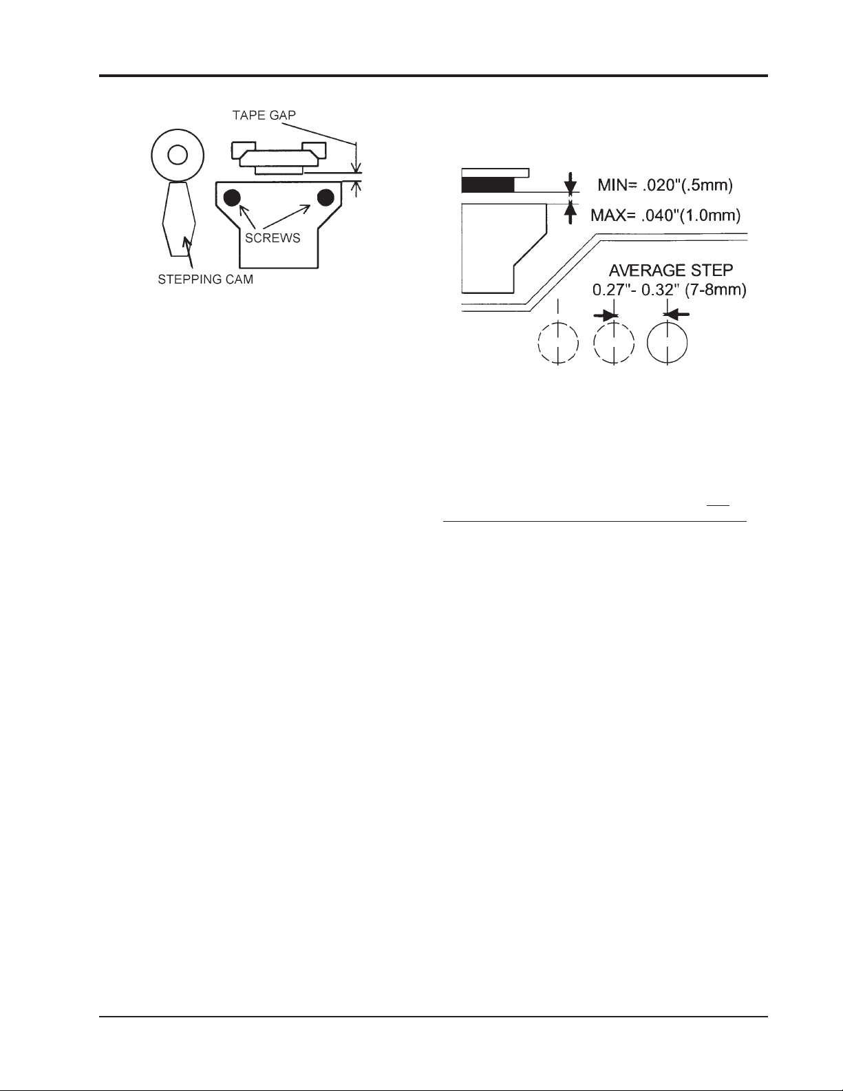
REMOTE INTELLIGENT SENSOR - AREA MONITOR
Figure 4-6. Stepping Clamp Vertical
With the stepping cam vertical, and gate
opening lever in the gate closed position, the optics
block can be replaced and the two screws put in
loosely. Position the optics block so that there is a
gap of 0.020" to 0.040" (0.5mm to 1.0mm) between
the two halves of the gate.
Ensure that the gap is parallel when it is
measured. Note that the plastic tubes connecting
the moving part can cause it to twist a little in its
pivot. This can make the gap closer at the top or the
bottom.
After initially setting the gap, tighten the block
fixing screws to lock the optics block in position.
Replace the connector (with the switch ‘off ’),
then, verify that the tape steps correctly as follows.
Place a length of tape in the gate. This can be
done by pulling a length out of a cassette which can
be placed on top of the unit, or held in one hand.
Avoid touching tape with bare fingers.
Switch ‘on’, and press the tape reset button to
step on the tape. Mark the edge of the block on the
tape with a pencil. Repeat the process until 4 or 5
steps are marked on the tape. Measure the length
of the tape steps and take an average. The average
step should be between 0.27" and 0.32", (7 to 8 mm).
If the steps are much longer, the cassette life
will be less than the quoted 30-day maximum. In
this case, the position of the optics block may be
adjusted by repeating the above process, but
reducing the gap gradually. Continue until a tape
step of approximately 0.32"(8 mm) is achieved. Do
not reduce the gap to less than 0.020" (0.5 mm) or
tape drag in the gate may occur. This condition may
be aggravated if the tape gets damp. Tape breakage
can occur under these conditions.
NOTE: In some cases it may not be
possible to reduce the tape gap below about
0.030" (0.75 mm), in this case leave it set
at that value.
NOTE: If it is not possible to achieve a
satisfactory average tape step length, please
refer to additional information in
Section 4.21.2.
Figure 4-7. Summary of Gate & Step Values
4.10.7 WHAT TO DO IF CLEANING DOES NOT
RECTIFY THE PROBLEM. If performance cannot
be improved, or if the change is marginal, it will be
necessary to replace the optics block. A new optics
block can be ordered from your distributor. When
ordering the replacement block, specify the
system gas type and range, also the serial number.
This information will ensure that the correct item is
supplied.
It should be appreciated that if the block is
replaced the original calibration of the instrument is
no longer valid. It may be assumed that, because of
manufacturing methods and testing, performance
with a replacement block will be within 10% of the
original. Factory re-calibration against gas is recommended as soon as is practicable.
A replacement block carried as a spare against
future need is a wise precaution for those applications where contamination of the input tube and
optics block is a problem.
RIS
4.11 CHANGING A PUMP
Providing that care is taken, this is not a
difficult procedure.
4.11.1 PREPARATION. Have available a replacement pump of the correct type. RIS systems with a
Flow Rate of 200 mL/min. or less are fitted with the
low flow pump and RIS’s with a Flow Rate higher
than 200 mL/min. are fitted with the high flow
pump. These catalog numbers specify the pump
complete with mounting bracket ready to fit.
Warn that the system is being taken out of
operation and that alarms may be activated during
the work. Remove external power from the RIS, open
the door and turn off SW1.
Instruction 2772-0803 Page 4-5
Page 40

REMOTE INTELLIGENT SENSOR - AREA MONITOR
4.11.2 REMOVAL OF THE MECHANICAL
CHASSIS. Remove the cassette, undo the two
ribbon cable connectors and the two hose couplings
in the tubes that connect the chassis to the body of
the instrument. Undo the three (captive) cap head
screws that secure the chassis (see Figure 4-8). A
2.5 mm hex key is required for this. The mechanical
chassis can now be lifted out.
Figure 4-8. Mechanical Chassis
4.11.3 PUMP REMOVAL. Turn the chassis cover
and remove three slot head screws (Figure 4-9) to
allow the pneumatic chassis to be folded out to give
access to the pump. It is not necessary to discon-
nect and remove the module.
Carefully disconnect tubes to the pump inlet
and outlet. Note original orientation and position,
for trouble free reconnecting. Disconnect input
wiring, and remove screws holding pump which can
now be withdrawn and discarded. Refer to Figure 4-10 which shows both pump types together
with the orientation of pump connections.
Figure 4-10. Pump Types
4.11.5 REPLACING THE MECHANICAL
CHASSIS AND SETTING PUMP FLOW. Care-
fully replace the chassis and route the tubes between chassis and body of the RIS as they were
originally. Check that the tube connections are
oriented correctly. Note, the blue tube (or white in
some cases) should be at the top and the green (or
clear) one should be at the bottom. Reconnect the
ribbon cable connectors, and tighten the three
screws.
The cassette can be replaced and power restored. Switch on SW1 and press the tape reset
button.
Enter the TEST Mode and set the pump flow as
described in Section 4.5.
On completion, return the system to service.
4.12 EXTERIOR CLEANING
An occasional wipe with a damp cloth is adequate in most circumstances. When oily or sticky
deposits build up, a mild detergent solution on the
cloth will normally remove them. Clean with the
door shut and avoid excessive water. It should not
be necessary to clean inside the instrument (except
when cleaning the optics block as described in
Section 4.10.5).
4.13 KEY PARAMETER CHECKS
Figure 4-9. Pneumatic Chassis
4.11.4 FITTING THE NEW PUMP. This is a
reversal of the procedure detailed above. Take care
that the correct pump is fitted and that everything
is put back in the original orientation. Make sure
that the pump moving parts are free to rotate
without anything fouling them.
Page 4-6 Instruction 2772-0803
It is recommended that the TEST Mode checks
are carried out at each cassette change. These are
as described in Section 2.8.
It is good practice to record the reading taken
on the form provided in the back of this manual. If
any value requires adjustment, the reading before
and after should be noted. If a system ‘fault’ occurs
the TEST Mode parameters at the time should be
Page 41

REMOTE INTELLIGENT SENSOR - AREA MONITOR
entered. These practices, if regularly carried out,
will build up an informative system history. This
will show trends and prove a useful diagnostic aid
should this be required. The time taken to check
and record parameters for each cassette change is
normally only a few minutes.
4.14 MECHANICAL TIGHTNESS
It is good practice to carry out an annual check
of mechanical security. The check should include:
4.14.1 CABLE GLANDS. Check that cable glands
are tight.
4.14.2 DOOR SWITCH. Make sure that the door
switch is correctly adjusted. The procedure for
checking and adjustment is in Section 4.7.
4.14.3 DOOR SEALS. Ensure the door seals are
effective. Also check that the door securing screws
are in sound condition and not strained to the point
that replacement is required. The door seals are
reliable and seldom need attention. Door securing
screws can be strained by over tightening and it is
recommended that spares are carried. The catalog
number is shown in Section 5.
4.14.4 SAMPLE INLET. It is ESSENTIAL that
the input tubes is properly engaged in the block.
Otherwise a suitable, undiluted, sample will not be
conveyed to the point of measurement.
There is no reason for the tube to become
displaced on its own, however the functional
importance of this element fully justifies a careful
check. Correct assembly of the input tubes is shown
in Figures 2-4 and 2-5.
4.14.5 INTERFACE TERMINAL SCREWS.
Check the screw in each used terminals for tightness.
4.15 INPUT PATH CLEANING
Occasionally, check for excessive paper dust in
the open tape gate. A check every 2 or 3 months is
usually adequate. If it is required, blow the tape
path and block clean with a hand bellows or can of
pressurized air. The use of a factory air line is not
recommended unless the air supply is known to be
filtered and dry and it is used carefully.
More extensive cleaning is not normally required unless sampling conditions are very dirty,
dusty, or otherwise adverse. If additional cleaning
proves necessary, see Section 4.10.
4.16 PUMP CHECK
Annually check the sampling pump for excessive
current and noise (see Section 4.8). These checks do
not require physical pump access but any further
examination, or pump replacement, will require
removal of the mechanical chassis in which the
pump is mounted.
Indicators of excess current and noise, referred
to above, may result from wear in motor bearings, or
the eccentric. Misalignment or looseness of the
motor relative to pump body is another possible
cause. If wear is the problem, replace the complete
motor/pump assembly. Misalignment, if not accompanied by wear, can be adjusted. For pump replacement catalog numbers see Section 5.
4.17 CHARCOAL FILTER & TUBING CHECK
Annually, or biannually, access the pneumatic
module (under the mechanical chassis), change the
filter and clean the tubing as necessary.
4.18 TROUBLESHOOTING GENERAL
The following sections assume the reader has
appropriate competence and skill. In case of any
doubt or difficulty refer to one of our Service Centers
for expert assistance.
4.19 EXCESSIVE INPUT CURRENT
Any increase in the input current should be
investigated and accounted for. The most likely
reasons for high input current are:
4.18.1 HIGH CHARGING CURRENT. This may
be due to normal recharging after an extended period
of power interruption and the system running on
battery support. If this is the case the charging current
will reduce to normal after a period of some hours.
Other reasons for an increase in charging current
include a badly adjusted input voltage (see Section
2.8.2.1), and a deteriorating battery.
4.18.2 HIGH PUMP CURRENT. The pump
running current can be checked as described in
Section 4.8. If it has increased significantly it is
generally an indication that the pump is worn and
needs replacing (Section 4.11).
4.20 LOW PUMP FLOW
If the flow, when checked at cassette change, is
found to have reduced significantly, check for the
cause. These could be:
Instruction 2772-0803 Page 4-7
Page 42

REMOTE INTELLIGENT SENSOR - AREA MONITOR
NOTE: The sections below do not refer to
the modest changes in flow that occur over
a period of time and are quickly adjusted
for with the appropriate potentiometer.
4.20.1 A FAULTY PUMP. If this is the case,
change the pump. Note that there are two pump
types, which are fitted depending upon the RIS
model. Refer to Sections 4.8 & 4.11 for guidance
including typical pump running current. Check
Section 5 for the correct catalog number.
4.20.2 A BADLY FITTED INPUT TUBE. Check
to ensure that the input tube(s) is correctly fitted
and that no leakage is occurring.
4.20.3 A FAULTY TAPE GATE SEAL. This
problem is only likely after several years operation.
It can occur through distortion, or wear, of the seal
as a result of the opening and closing of the gate
over an extended period. Replacing the seal requires special knowledge, and should be referred to
one of our Service Centers.
4.20.4 LEAKING OR LOOSE TUBING. Check
to ensure that all of the pipe work in the mechanical chassis is sound and properly connected.
4.21 EXCESSIVE TAPE USE
Cassettes lasting appreciably less than 30 days
may be due to:
4.21.1 MONITORED CONCENTRATION
LEVELS HIGH. During periods when significant
levels are monitored, the system will use each track
only once; it will also operate in the ‘time mode’ if
the sample concentration is high enough. Both
conditions will increase tape consumption.
4.21.2 EXCESSIVE STEP LENGTH. This can
occur because an undue amount of tape is pulled
through the gate at each step. The average step
length should be 0.027" to 0.032" (7 to 8 mm) and
the method of measuring it is described in Section
4.10.6. This condition, if present, may be caused by
high take-up clutch torque, a weak pinch roller arm
spring, a maladjusted tape gate, or a combination of
these factors. Rectification is considered a Service
Center repair.
4.22 TAPE BREAKAGE
Tapes can be damaged by careless insertion of a
new cassette. Take care, as it is difficult to repair a
broken tape. If the tape breaks during normal
operation check that the tape is not damp which
would reduce its strength. Tape breakage can also
occur if the tape gate gap is too small. If this is the
case, the take-up clutch will pull against the constraints of the gate causing the tape to break. The
tape-gate gap can be checked as in Section 4.10.6.
If the two ends of a broken tape can be ‘fished
out’ of the cassette body they can be repaired by
careful joining with adhesive tape. The join must
then be completely wound onto the take-up spool so
that it does not pass through the tape gate when
operation resumes.
CAUTION
Do not touch tape with bare fingers to
avoid contact with chemicals on the tape.
4.23 LIGHT FAULTS
If Light Faults occur, check (in the TEST Mode)
that the light level values are at, or close to 220. If
not, adjust as covered in Section 4.4. Make sure
when adjusting that the tape in the gate, when the
adjustment is made, is clean and not stained.
If the light level when checked is found to be
correct at, or close to, 220 make sure that it is not
possible that some external bright light (natural or
artificial) does not shine directly up the input
tube(s).
Remember that opening the tape gate without
putting the system into the TEST Mode can cause a
light fault as well as a spurious gas alarm.
If no apparent reason for frequent light faults is
found refer to one of our Service Centers for assistance.
4.24 DOOR FAULT
If the door fault is intermittent or the door
needs excessive tightening of the screws to turn it
off, or if it cannot be turned off, adjust the switch.
This is covered in Section 4.7.
Page 4-8 Instruction 2772-0803
Page 43
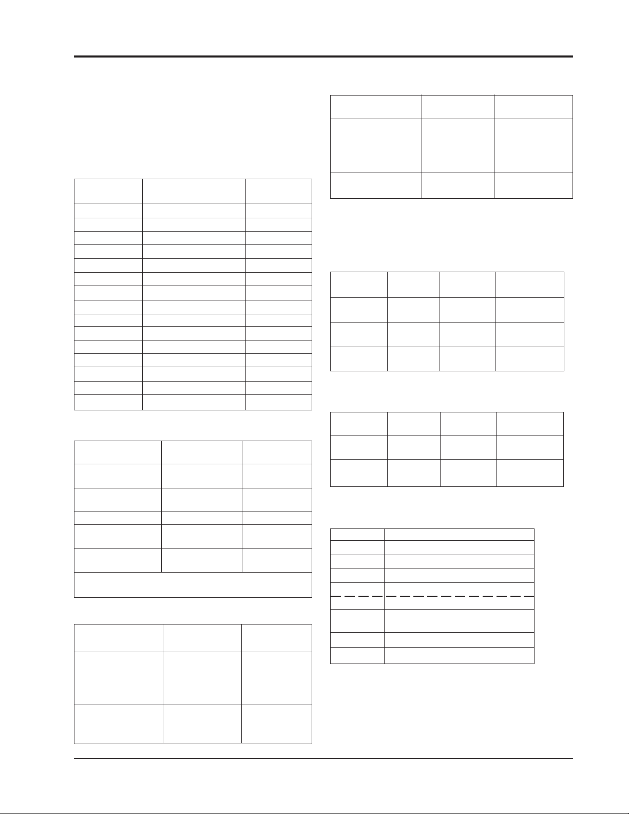
REMOTE INTELLIGENT SENSOR - AREA MONITOR
5 SYSTEM SPARE PARTS
5.1 MODEL DEPENDENT PARTS
Some parts are model dependent (see the tables
below). The other parts are common to all models.
5.1.1 CASSETTE
INSTRUMENT GAS TYPE CASSETTE
CAT.# CAT.#
2772-0010 TDI 2772-1010
2772-0015 TDI HIGH RANGE 2772-1010
2772-0020 HYDRAZINES 2772-1020
2772-0030 PHOSGENE (A) 2772-1030
2772-0035 VELCORIN® 2772-1035
2772-0040 CHLORINE 2772-1040
2772-0060 ARSINE 2772-1060
2772-0090 ACID GASES 2772-1090
2772-0095 HCl HIGH RESOLUTION 2772-1090
2772-0100 HDI 2772-1100
2772-0110 PHOSGENE (B) 2772-1110
2772-0120 MDI 2772-1120
2772-0150 IPDI (VAPOR) 2772-1150
2772-0160 TDI, MDI, IPDI 2772-1120
2772-0175 TDI HIGH FLOW 2772-1120
5.1.4 PUMP ASSEMBLY
RIS CAT.# NOTE BATTERY
CAT.#
2772-0010, -0015, Low Flow 2701-1748
-0020, -0030, -0035,
-0040, -0060, -0090,
-0095, -0100, -0110,
-0150
2772-0120, -0160 High Flow 2701-2078
-0175
5.2 SYSTEM POWER SUPPLIES
5.2.1 SINGLE POINT
CAT. # INPUT OUTPUT TERRITORY
VAC
2772-2041 120 12V, America &
900mA Canada
2772-2042 220 12V, Europe
800mA
2772-2043 240 12V, U K
800mA
5.2.2 MULTIPOINT
5.1.2 OPTIC BLOCK
RIS CAT.# NOTE BLOCK
CAT.#
2772-0010, -0020, High Sensitivity 2701-1490
0015, -0035
2772-0030, -0060, Low Sensitivity 2701-1491
0100, -0110, -0150
2772-0120 Aerosol 2701-1704
2772-0040, -0090 Low Sensitivity 2701-1906
Coated
2772-0095 High Sensitivity 2701-2472
Coated
CAUTION: Recalibration is Required After Replacing
a Block.
5.1.3 BACK-UP BATTERY
RIS CAT.# NOTE BATTERY
CAT.#
2772-0010, -0015, Battery (with 2772-2084
-0020, -0030, -0035, resistor)
-0040, -0060, -0090,
-0095, -0100, -0110,
-0150
2772-0120, -0160 Battery 2701-1713
-0175 (without
resistor)
CAT. # INPUT OUTPUT TERRITORY
VAC
2772-2022 120 12V, America &
1.8A Canada
2772-2024 220/240 12V, Europe &
1.8A UK
5.3 RECOMMENDED SPARES
CAT. # DESCRIPTION
2701-0969 40mm Charcoal Filter
2701-1173 Tri-Lock Door Key
2701-1255 Tri-Lock Screw
2701-1311* FEP Teflon 3" Inlet Tube, Low Flow
2701-0577* FEP Teflon (above) bulk by the inch
2701-1424* FEP Inlet Tube, High Flow
in bulk by the inch
2701-1748 Pump Assy., Low Flow (Table #1)
2701-2078 Pump Assy., High Flow (Table #1)
* See Section 2.6 (Sample Lines)
Instruction 2772-0803 Page 5-1
Page 44

REMOTE INTELLIGENT SENSOR - AREA MONITOR
5.4 COMMON PARTS
CAT. # DESCRIPTION
2701-1072 Polycarbonate Window **
2701-1638 Door Keypad ** order these tw
items together. Not supplied
separately
2701-1089 Trumpet Cable Gland PG-9
2701-1489 Polyglass Enclosure Assy.
(Low Flow instruments)
2701-1716 Polyglass Enclosure Assy.
(High Flow instruments ONLY)
2701-0695 Optics PCB Assembly
2701-1760 Baseboard PCB Assembly
2701-2246 Gate Mechanism Spring
2701-2256 Clutch Assy. (spring type)
2701-0101 Motor/Gearbox (Drives stepping
cam and take-up spool etc.)
5.6 SERVICE CENTERS
5.5 OPTIONS AND SUPPLIES
CAT. # DESCRIPTION
2772-0251 Serial Printer Interface PCB
2772-2079 Portable Prnter 110/120 VAC
2772-2078 Portable Printer 220 VAC
2772-2077 Portable Printer 240 VAC
2772-2083 Portable Printer Cable
2701-1347 Replacement Printer Ribbon
2701-1387 Replacement Printer Paper Roll
2772-2081 Alarm Module
2701-1761 Alarm Relay PCB
2701-2149 Test Card
2701-2505 Magnet (Used with Test Card)
Pennsylvania
Scott Instruments
251 Welsh Pool Road
Exton, PA 19341
Phone: 610-363-5450 or
1-800-634-4046
Fax: 484-875-1610
Bacharach
621 Hunt Valley Circle
New Kensington, PA 15068
Phone: 724-334-5051
Fax: 724-334-5723
E-mail: help@bacharach-inc.com
Page 5-2 Instruction 2772-0803
Page 45

SUPPLEMENT A
A1 EARLIER RIS BASE BOARDS
A1.1 ADJUSTING LIGHT LEVELS ON PHASE 1 RIS UNITS
boards have been given in the main manual (Sections 1.1, 1.3.7, 2.8.2.1, & 4.4) Any
references to Figure 2-3 should be refered to Figure S-3.
mounted under the tape cassette which has to be removed before the light levels can be
adjusted as explained below:
the display has cycled to show:
REMOTE INTELLIGENT SENSOR - AREA MONITOR
Several references to RlS’s manufactured before April 1992 with phase 1 base
The light level adjustment POTs for boards manufactured before April 1992 are
Enter the TEST Mode by pressing the red button on the back of the door. Wait until
Press the HOLD/RELEASE button
on the front panel firmly so that
the display shows:
200 to 254
1
200 to 254
1
HOLD
Figure S-1. Test Mode
This display status will be maintained for 5 minutes, or until the HOLD/RELEASE
button is pressed again.
Adjustment is made by means of the two potentiometers that are located under the
cassette position and accessed through holes in the top plate. The light level track 1 is
adjusted by one, and track 2 by the other. The potentiometer access holes cannot be
seen until the cassette is removed. See Figure S-2.
Figure S-2. Pre-4/92 Light Level Access Holes
Adjustment method ‘a’. Make sure that tape in the gate is clean and unstained.
Close the tape gate. Observe the displayed light level for track 1 and decide if it needs
increasing or decreasing.
Open the tape gate and remove the cassette, turn the appropriate potentiometer a
little clockwise to decrease, or counter clockwise to increase, the light level.
Reinstall the cassette and check the light level value; if necessary repeat this
process until a value of 220 is achieved.
Instruction 2772-0803 Page S-A1
Page 46

REMOTE INTELLIGENT SENSOR - AREA MONITOR
Adjustment method ‘b’. Remove the cassette and pull out a loop of several
inches of tape. Insert a portion in the gate while the cassette is held in one hand; or
placed on the top of the RIS. Do not touch tape with bare fingers to avoid
contact with the chemicals on the tape.
With the tape in the gate and the cassette supported in one hand, adjust the
potentiometer with the other hand until the reading is 220. Counterclockwise
rotation of potentiometers increases the level.
When track 1 has been adjusted by either of the above methods, press the
HOLD/RELEASE button to allow track 2 to be displayed. HOLD this display as
before and adjust the same as track 1.
After adjustments have been made, rewind the tape pulled out of the cassette
(if the second method was used). Replace the cassette and close the gate. Exit the
TEST Mode by pressing the red button on the rear of the door again, unless other
tests have to be done.
Exit the TEST Mode by pressing the red button on the rear of the door again,
unless other tests have to be done.
Page S-A2 Instruction 2772-0803
Page 47

REMOTE INTELLIGENT SENSOR - AREA MONITOR
Figure S-3. Phase 1 Base Board Terminal Strip Identifications
Instruction 2772-0803 Page S-A3
Page 48
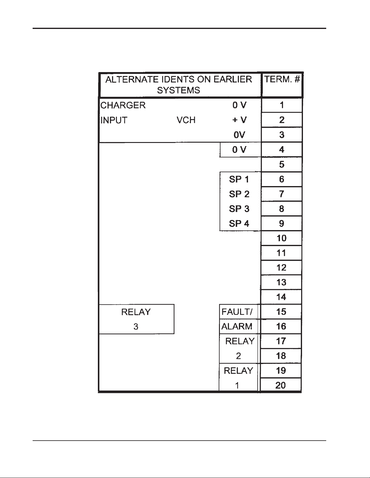
REMOTE INTELLIGENT SENSOR - AREA MONITOR
Figure S-4. Phase 2 (Early Version)
Base Board Terminal Strip Identifications
Page S-A4 Instruction 2772-0803
Page 49

®
 Loading...