

Page 1
Introduction
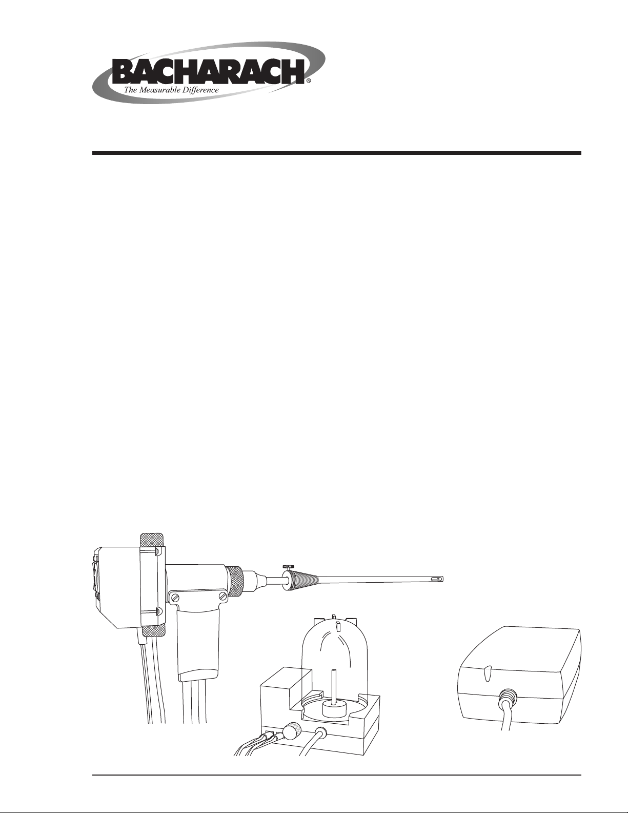
The Bacharach Flue-Gas Sample Conditioning System consists of the
following components:
• Probe with Peltier Cooler
• Condensate Pump with Water Trap
• Power Supply
The function of this system is to remove water vapor from the ue-gas
sample, thus preventing the formation of water droplets inside the
probe hose. If water droplets were to form inside the hose, a portion of
the gas sample could be absorbed by the water, thus resulting in lowerthan-actual readings of NO2 and SO2.
Instruction 24-9415
Flue-Gas Sample
Conditioning System
P/N 24-7224
Rev. 5 – June 2005
Water vapor is removed from the ue-gas sample by passing the sample
through a Peltier Cooler where the sample is chilled, which in turn,
causes the water vapor contained in the gas sample to be removed from
the sample.
The water that was extracted from the gas sample is then pumped out
of the Peltier Cooler and into a water trap.
The now dry, conditioned ue-gas sample is then sent to its associated
combustion test equipment for analysis.
Figure 1. Flue-Gas Sample Conditioning System
Probe w/ Peltier Cooler
Power Supply
Pump
w/ Water Trap
Product Leadership • Training • Service • Reliability
Page 2

Technical Data
Probe:
Standard Length ......................................................... 11.5 in (295 mm)
Optional Lengths ............................................................. 7 in (180 mm)
19.5 in (500 mm)
39 in (1000 mm)
Peltier Cooler:
Inlet Sample Dew Point.......................................... 149 °F (65 °C) max.
Outlet Sample Dew Point .................18 °F (10 °C) min. below ambient
Cooling Power ................................................................................. 10 W
Environment Temperature .............................32 to 104 °F (0 to 40 °C)
Weight ................................................................................8.5 oz (240 g)
Condensate Pump:
Sample Flow Rate ..........................................................1.5 LPM @ STP
Length of Hose ...................................................................... 6.6 ft (2 m)
Reservoir Storage ........................................................................... 50 ml
Environment Temperature .............................32 to 104 °F (0 to 40 °C)
Weight ..............................................................................12.7 oz (360 g)
Flue Gas Sample Conditioning System
Power Supply:
Input .............................................................. 100 to 240 VAC, 50/60 Hz
Output ............................................................ 9 VDC, max. @ 4 A, max.
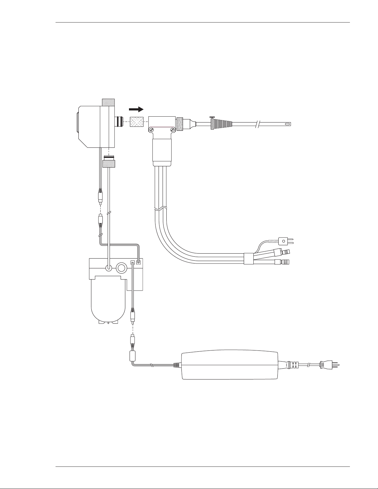
Equipment Setup
Refer to Figure 2. If not already done, attach the Peltier cooler to the
probe assembly by rst removing the plastic end cap from the rear of
the probe, and then inserting the cooler’s inlet connector, ensuring rst
that a lter is present between the cooler and probe.
Attach the pump’s inlet hose to the bottom of the Peltier cooler. Water
that is condensed from the ue-gas sample will be pumped into the condensate pump’s reservoir through this hose. Note that the condensate
pump can be placed in an upright, horizontal, or hanging position. A
magnet mounted in the base of the pump allows the pump to be attached to overhead ductwork.
Connect the power supply’s DC output connector to the condensate
pump; then connect the condensate pump’s DC output power connector
to the Peltier cooler. The Peltier cooler and its associated condensate
pump are started by plugging the power supply into a source of AC
power that is between 100 and 240 VAC, 50/60 Hz.
Connect the probe assembly’s stack-temperature thermocouple con-
nector, pressure tting, and ue-gas tting to the combustion analyzer
per the analyzer’s instruction manual.
2 Bacharach, Inc. Instruction 24-9415
Page 3
Flue Gas Sample Conditioning System
PELTIER
COOLER
PROBE ASSEMBLY
PUMP
POWER SUPPLY
100 – 240 VAC
50/60 HZ
Connect to
Combustion Test
Equipment
STACK TEMP.
THERMOCOUPLE
PRESSURE (Blue)
FLUE GAS (Yellow)
Figure 2. Equipment Setup
Instruction 24-9415 Bacharach, Inc. 3
Page 4

Operation
Flue Gas Sample Conditioning System
When ready to conduct a combustion efciency test, plug in the power
supply of the Flue-Gas Sample Conditioning System. You should hear
the condensate pump start running and see the Peltier cooler’s red LED
turn on and off as the cooler is cycled. Note that the cooler’s operating
time changes according to its temperature.
Set up and congure the combustion analyzer as described in its instruction manual. Then insert the probe into the ue stack and begin
testing.
During the combustion test, the condensed water vapor from the ue
gas will accumulate inside the pump’s reservoir. If the water level begins to approach the ends of the tubes inside the reservoir, then stop the
test and empty the reservoir as described in the Maintenance Section of
this manual.
WARNING! The probe tube is hot! In the following step, be
sure to allow the probe tube sufcient time to cool before
handling.
At the conclusion of the combustion test, remove the probe from the
stack; then unplug the Peltier cooler’s power supply.
4 Bacharach, Inc. Instruction 24-9415
Page 5

Flue Gas Sample Conditioning System
Maintenance
Probe
The probe’s sponge-type lter (Figure 3, Item 9) needs to be inspected at
regular intervals for dirt contamination. Replace lter as necessary by
rst pulling out the Peltier cooler from the probe and then exchanging
the lter with a new one.
Peltier Cooler
The cooler’s wadding lter (Figure 3, Item 12) needs to be inspected at
regular intervals for dirt contamination. Replace lter as necessary by
rst pulling off the lter chamber’s top cap and then exchanging the
lter with a new one.
Condensate Pump
WARNING! The condensed water will be warm and slightly
acidic. Take all necessary precautions to prevent the water
from splashing into your eyes or contacting your skin.
Empty the pump’s reservoir (Figure 3, Item 15) by rst holding the
pump with its reservoir facing downwards. Then twist the reservoir 90
degrees (either clockwise or counterclockwise) to free it from the pump
base. Empty the reservoir; then reattach it to the pump. Before reattaching the reservoir, however, make sure that the reservoir’s o-ring
(Figure 3, Item 20) is properly positioned inside its grove in the pump
base.
The pump’s wadding lter (Figure 3, Item 17) needs to be inspected at
regular intervals for dirt contamination. Replace lter as necessary by
rst unscrewing the lter chamber cap and then exchanging the lter
with a new one.
Instruction 24-9415 Bacharach, Inc. 5
Page 6

Replacement Parts
Item Description Part No.
(Fig 3)
Probe:
1 Complete Assembly (w/ 11.5 in. probe tube)................. 24-3038
2 Probe Tubes:
7 in. (180 mm) .......................................................... 24-1183
11.5 in. (295 mm) ..................................................... 24-1184
19.5 in. (500 mm) ..................................................... 24-1185
39 in. (1000 mm) ...................................................... 24-1186
3 Gas Hose Fitting ............................................................ 24-0877
4 Draft Hose Fitting .......................................................... 24-0878
5 Probe Stop ...................................................................... 19-3037
6 Thumb Screw ............................................................... 102-0875
7 Screw, M4 x 6mm ......................................................... 501-3829
8 Retaining Nut ............................................................... 102-3740
9 Filter (Qty. 5).................................................................. 07-1646
Flue Gas Sample Conditioning System
Peltier Cooler & Power Supply:
10 Complete Assembly, Peltier Cooler & Power
Supply (AC Power Cord not included) ....................... 24-1179
11 Plastic End Cap ............................................................ 106-5454
12 Filter Wadding ............................................................... 07-1647
13 Power Supply ............................................................... 304-1713
14 AC Power Supply Cord, 3-Wire ................................. 4998-8986
Condensate Pump:
15 Complete Assembly ........................................................ 24-1180
16 Reservoir ...................................................................... 106-5453
17 Plastic Screw-On Cap .................................................. 106-5455
18 Filter Wadding (Qty. 1) .................................................. 24-1205
19 Plastic Cap w/ Drain .................................................... 106-5456
O-Rings:
20 9 x 2 mm ....................................................................... 105-5105
21 4 x 1.75 mm .................................................................. 105-5106
22 50 x 3 mm ..................................................................... 105-5107
23 11 x 1 mm ..................................................................... 105-5108
6 Bacharach, Inc. Instruction 24-9415
Page 7

Flue Gas Sample Conditioning System
11
20
20
12
Part of Item 10
1
21
9
6
7 8 5 2
Part of Item 10
13 14
18
23
17
22
16
20
19
15
Figure 3. Replacement Parts
Instruction 24-9415 Bacharach, Inc. 7
Page 8

Bacharach Sales/Service Centers
Service can be obtained by contacting a Bacharach Service
Center at the following locations:
United States
Bacharach Sales/Service Center
621 Hunt Valley Circle
New Kensington, PA 15068
Phone: 724-334-5051
Fax: 724-334-5723
Email: help@bacharach-inc.com
Canada
Bacharach of Canada, Inc.
250 Shields Court Unit #3
Markham, Ontario L3R 9W7 Canada
Phone: 905-470-8985
Fax: 905-470-8963
Email: bachcan@idirect.com
Flue Gas Sample Conditioning System
México
Bacharach de México
Playa Regatas No. 473 Tercer Piso
Col. Militar Marte
Delegación Iztacalco, 08830
México D.F. México
Phones: +52-555-634-7740
+52-555-634-7741
Fax: +52-555-634-7738
Email: bacharachservicio@bacharach.com.mx
Europe
European Headquarters
Bacharach Instruments
Sovereign House, Queensway
Royal Leamington Spa
Warwickshire CV31 3JR
United Kingdom
Phone: +44-1926-338111
Fax: +44-1926-338110
Email: sales@bacharach-europe.com
8 Bacharach, Inc. Instruction 24-9415
Page 9

Flue Gas Sample Conditioning System
Instruction 24-9415 Bacharach, Inc. 9
Page 10

621 Hunt Valley Circle, New Kensington, PA 15068
Headquarters:
Ph: 724-334-5000 • Fax: 724-334-5001 • Toll Free: 800-736-4666
Website: www.bacharach-inc.com • E-mail: help@bacharach-inc.com
Printed in U.S.A. ® Registered Trademark
Copyright © Bacharach, Inc. 2000 – 2005
 Loading...