

B52 ELP 36.4, ELP 32.2, Elp 5.2, ELP 52.1D Instruction Manual
MOBILE ENTERTAINMENT SYSTEM
INSTRUCTIONS MANUAL
ELP 36.4
4 CHANNEL HIGH PERFORMANCE
POWER AMPLIFIER
Thank you for purchasing the amplifier 36.4 and your interest in products B52.
Read this manual carefully before installing your new amplifier.
www.b52audio.com
ENGLISH

Before Installation ........................................................................................................3
Features and Descriptions ............................................................................................4
Installation ...................................................................................................................5
Electrical diagram .........................................................................................................6
Troubleshooting ...........................................................................................................8
Specifications ...............................................................................................................9
INDEX
2
WARNING
Before installing your new amplifier, make sure the fuse is properly installed.
Never change the value of the fuses. Use the fuses with the current and rated voltage in this
manual. Otherwise, it may cause a short circuit, smoke or even an explosion.
Do not install this unit in a location that would interfere with operation of the vehicle or may
cause injury to a passenger as a result of breaking.
To ensure proper operation of this unit while maintaining good thermal dissipation, be sure to
leave enough space above the amplifier for proper ventilation. Do not cover the amplifier with a
carpet or blanket.
Connect the cable (+) battery to the positive terminal of the amplifier (B +) and ground wire
(GND) of the amplifier to the vehicle chassis.
This unit is for installation of 12V and negative grounding. Before performing an installation in a
van, truck or bus, check the battery voltage.
The black wire is the ground wire.
When installing this unit, always connect the ground wire first. Check the ground wire is properly
connected to the vehicle chassis.
If by some factor, the cable connected to the vehicle, is loosen or falls could result in fire, smoke
or failure.
The amplifier must be installed on a flat surface. Installing it on a surface that is flat or bumpy,
may cause defective operation.
Do not let this unit, contact with liquids that could lead to electric shock, smoke or overheating.
If by any problem with the instalation of this amplifier, the fuse blows. Disconnect the cables and
check all connections (power and speakers). Once you determine and solve the problem, replace
the fuse / s for a new nominal current and voltage identical.
If none of these works, contact your nearest dealer.
BEFORE INSTALLATION
3
4
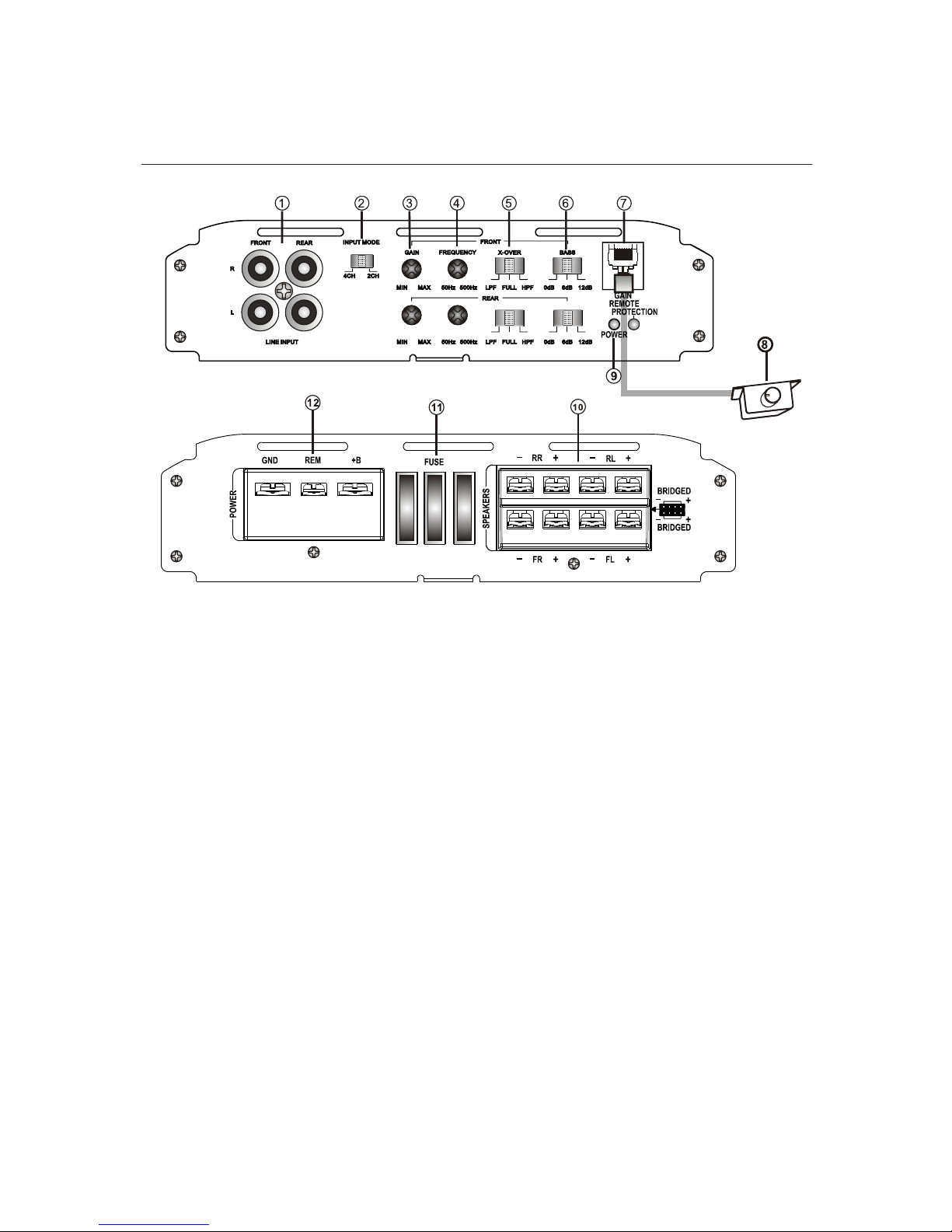
1. Low Level INPUT
RCA connector low level input connected to the speakers of the main unit.
2. High Level INPUT
Input connector plug connected to high-level speakers from the main unit.
NOTE: Do not connect cables high level input if you use the low level RCA input
3. Gain Adjustment (GAIN)
Adjust to obtain the desired volume without distortion.
4. X-OVER: Cutoff Frequency Selector
Selector HPF (High Pass Filter) / LPF (Low Pass Filter) / FULL.
5. Cutoff frequency control X-OVER (50Hz-500Hz)
Frequency selector for high pass and low pass.
6. Bass Boost (Bass Boost)
Selectable 0dB / +6 dB / +12 dB
7. LED indicator
GREEN LED: Indicates normal amplifier operation
RED LED: Indicates the protection mode
8. Output for Remote Controller
Turn the gain (GAIN) to the maximum before using the remote control.
DESCRIPTION OF FUNCTIONS
9. Remote Control
Gain adjustment from 0.2 V to +6 V
FEATURES AND DESCRIPTIONS
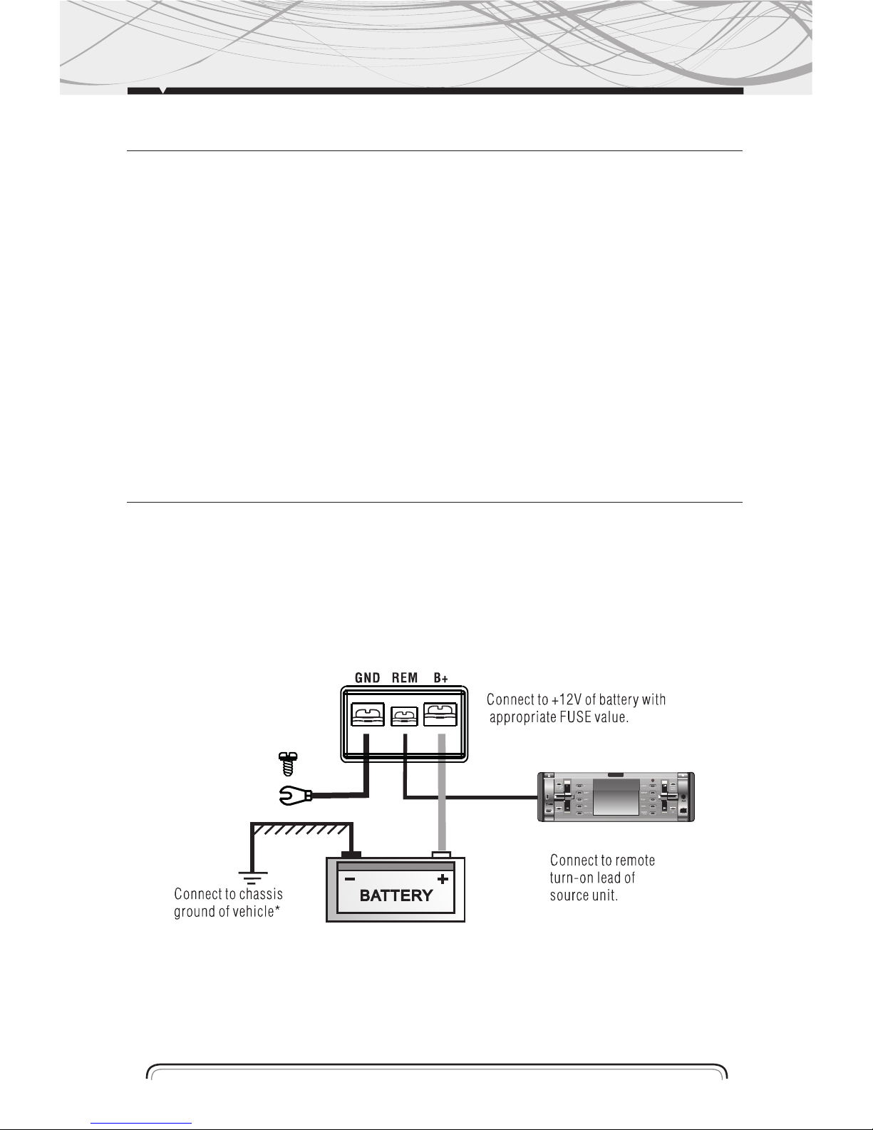
INSTALLATION
Connect the cable (+) battery to the positive terminal of the amplifier (B +) and ground wire
(GND) of the amplifier to the vehicle chassis. The cable terminal (REM) the terminal cable must
be connected to the stereo remote control
The black wire is the ground wire. When installing this unit, always connect the ground wire first.
Check the ground wire is properly connected to the chassis of the vehicle
Note
To prevent the ground wire (GND) to loosen or fall off the vehicle chassis, you can install a screw
and nut self-braking.
5
10. Fuse Holder
Only replace fuses with same rating fuses
11. Speaker connection terminals
12. (GND) Ground Wire Terminal
A Node connection to the vehicle chassis.
(REM) Remote Control Terminal at Stereo
The terminal (REM) is connected by remote cable to the main unit.
The voltage must be between 10 and 15 VDC
(B +) Terminal of Cable Positive
Power connection terminal. Connect to the anode of the car battery.
FEATURES AND DESCRIPTIONS

ELECTRICAL DIAGRAM
a. Configuration Diagram for 4-Channel Stereo
6
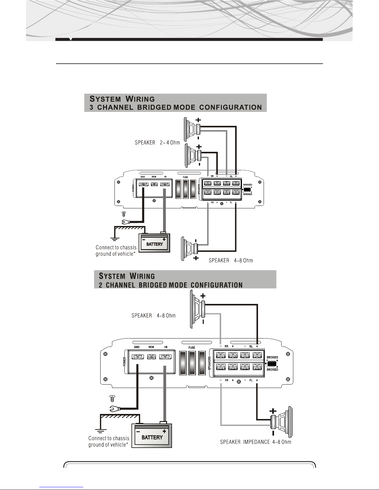
ELECTRICAL DIAGRAM
a. Mode Setup diagram Bridge (Bridge)
7

Troubleshooting
Before installing your amplifier, read the notes you see below and follow the procedures. Always
test the speakers and their cables before installing them in the vehicle.
No power
Check if the ground wire (GND) is properly installed.
Check dif the arrival of energy in the terminal (B +).
Check the fuses.
Check if the LED is turning it protection. it it is, turn the amplifier off for a few minutes and then on
again.
Shrill whistle or engine noise in speakers
Disconnect each of the RCA inputs on the amplifier until the hissing disappears. If the hiss disappears, then replace the cables. If by changing cables, whistling doesn´t disappear, check that the
main drive cables are not touching other wires of the vehicle.
The best way to establish the level of the amplifier is putting his gain to the maximum. Try to raise
the signal level on the main unit as much as possible and see if the hiss decreases.
Protection LED is activated when the amplifier is operating
Check for a short-circuit in the line of speakers.
Turn off the amplifier, disconnect all the speakers and turn on the amplifier. If the protection LED
turns on again, then is the amplifier is not working properly.
If the heat sink temperature exceeds 85° C, the power supply is disconnected automatically This
protecting the amplifier against a damage.
The amplifier overheats
Verify that the minimum speaker impedance is correct for the amplifier.
Check if the speaker wires have a short circuit.
Make sure if there is enough ventilation over the amplifier.
The sound is distorted
Verify that the gain control of the main unit is correct.
Check that all crossover frequencies are configured correctly.
Verify that the speaker wires are not touching each other.
Squealing noise in the speakers
The squeak maybe caused by a damaged cable or poor contact on the ground.
TROUBLESHOOTING
8

Specifications
Model ELP 36.4
Power @ 14.4VDC .
Maximum Power in Bridged Mode @ 4 Oh 3600W x 2
Maximum Power @ 2 Ohms 1800W x 4
RMS Power @ 4 Ohms 330W x 4
RMS Power @ 2 Ohms 500W x 4
Signal to Noise Ratio 95dB
(THD) 0.01%
Channel Separation (@1Khz) 50dB
Frequency Response 15Hz – 30KHz
Input Sensitivity 200mV – 6V
Input Impedance 15KOhm
Minimum Speaker Impedance 2 Ohms
Crossover Low Pass Filter 50Hz – 500Hz
Bass Boost 0dB - +12dB
High Pass Filter 50Hz – 500Hz
Remote Gain Control 200mV + 6V
Fuse Rating 25A x 2
Dimensions (W x H x D) 200 x 49 x 524 mm
ESPECIFICATIONS
9

www.b52audio.com
NOTES
 Loading...