

Page 1
MODEL: zero1 Product id:zero116d
Zero1
OWNER’S MANUAL
Page 2
Introduction
We thank you for purchasing our amplifiers. Your decision to be part of something different is what we strive for.
Our products reflects who we are, going to the extent to deliver you our finest comes natural.
to upgrade the stock electrical system. Ensure the system is in accordance with the full performance of the amplifier.
Better Bass
Better Bass is our philosophy of adding something extra.
Keep in mind that continious exposure to SPL above 100 dB can seriously
damage your hearing. Today’s high power auto sound systems can easily
produce SPL over 140 dB. Enjoy your music with sense.
Table of contents
Design features 3
Panel layout 4 - 5
Installation 6
*Preparations 6
*Power connectors 6
*remote & RCA input 6
wiring layout 7
speaker wiring - single amp 8
strapped speaker wiring 8
* strapping / linking steps 9
strapped control panel setting 10
* Master / slave 1 10
* strapping / linking steps 10
Daisy chain - Master / slave2 11
troubleshooting 12
2
Page 3
Design features
Zero1
Circuit Configuration: HI-EF Class D
Frequency Response: 15 Hz ~ 250 Hz
Signal to Noise Ratio: > 100 dB
Input Sensitivity: 6 V ~ 0.2 V
Crossover Circuit: 24 dB / Octave
Low Pass Crossover: 35 Hz ~ 250 Hz
Subsonic Crossover: 10 ~50 Hz
Damping Factor: > 300
Bass Boost Frequency: 30 Hz ~ 80 Hz
Bass Boost: 0 ~ 9 db
Phase: 0 ~ 180°
Remote Control w/ Clip indicator: Included
Power Terminal Gauge: 0 GA x 2
Fuse Rating: 300A
Dimensions: 18.9’’ x 11.8’’ x 2.6’’ / 480 mm x 300 mm x 64 mm
Specifications
Continious output power (RMS)
(12 V < 1% THD) (14,4 V < 1% THD) (15 V < 5% THD)
Power @ 4 Ω: 900 W x 1 1400 W x 1
Power @ 2 Ω: 1600 W x 1 2000 W x 1
Power @ 1 Ω: 2500 W x 1 3000 W x 1
Description of specifications
Stable impedance load of the Zero1 is 1 Ohm.
* Speaker overload
* Short circuit
* Input Voltage - RCA & Power Supply
5000 W x 1
Operational voltage 9~15v
3
Page 4
Design features
Zero1
Circuit Configuration: HI-EF Class D
Frequency Response: 15 Hz ~ 250 Hz
Signal to Noise Ratio: > 100 dB
Input Sensitivity: 6 V ~ 0.2 V
Crossover Circuit: 24 dB / Octave
Low Pass Crossover: 35 Hz ~ 250 Hz
Subsonic Crossover: 10 ~50 Hz
Damping Factor: > 300
Bass Boost Frequency: 30 Hz ~ 80 Hz
Bass Boost: 0 ~ 9 db
Phase: 0 ~ 180°
Remote Control w/ Clip indicator: Included
Power Terminal Gauge: 0 GA x 2
Fuse Rating: 300A
Dimensions: 18.9’’ x 11.8’’ x 2.6’’ / 480 mm x 300 mm x 64 mm
Specifications
Continious output power (RMS)
(12 V < 1% THD) (14,4 V < 1% THD) (15 V < 5% THD)
Power @ 4 Ω: 900 W x 1 1400 W x 1
Power @ 2 Ω: 1600 W x 1 2000 W x 1
Power @ 1 Ω: 2500 W x 1 3000 W x 1
Description of specifications
Stable impedance load of the Zero1 is 1 Ohm.
* Speaker overload
* Short circuit
* Input Voltage - RCA & Power Supply
5000 W x 1
Operational voltage 9~15v
3
Page 5
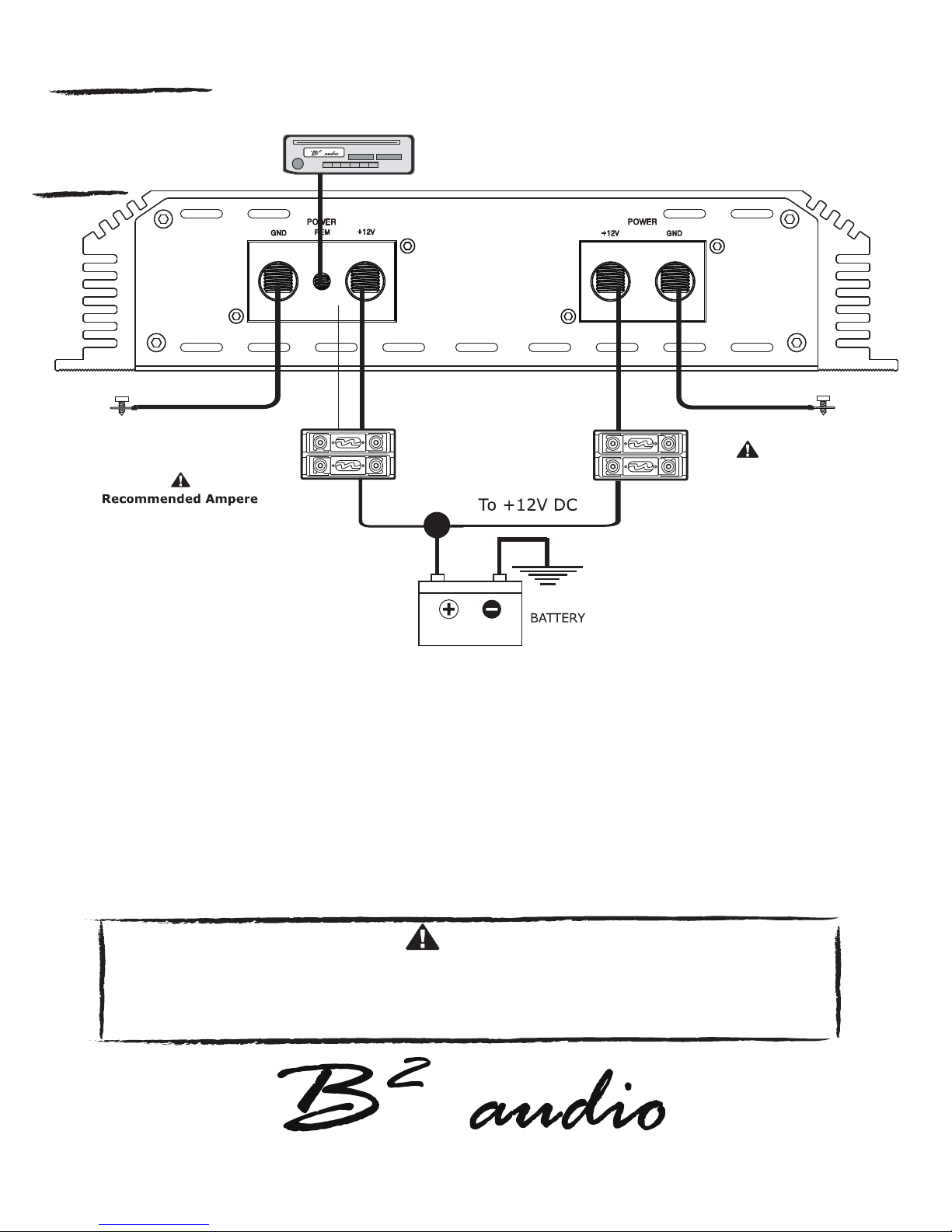
Panel layout
Zero1
Head unit
GROUND*
300A (External fuse)
GND (GROUND CONNECTION) + 12V (POWER CONNECTION)
GROUND*
* Keep ground as short as possible and of
equal length, no longer than 20” (50 cm).
This drawing is for illustration purpose only!
Connects to the vehicle’s chassis. Connects to the positive terminal of the battery.
Keep as short as possible (< 20” / 50 cm) For specied performance 0 Ga cable is required.
Use minimum 0 Ga cable for optimal conditions. Fuses shall be placed within 8” / 20 cm of the battery.
The HI-EF class D design allows for higher output
REM (REMOTE) power, even at low voltage applications.
Connects to switched +12V from the headunit. This sets high requirements to the battery system.
Choose batteries with high CCA ratio.
Installation of the amplifier shall be done in the following steps:
1. Connect the +12V wire, keep in mind this wire has to be fused at the battery as well. 2. Ensure the ground is
appropriate, then connect it to the amplier. 3. Connect the switched remote. 4. Reattach negative wire (ground)
to the battery. 5. Operation over 16V will cause the amplier to go into protect & can void the warranty!
CAUTION
5
Page 6

Installation
Installation considerations
If you choose to install the amplier by yourself, please read the entire owner’s manual carefully.
Before you start your installation, please take all steps into consideration.
If in doubt, please go to www.b2audio.com for authorized distributors / dealers that will be able to
congure your set up & ensure the warranty of your amplier.
Preparation
Disconnect the negative (-) battery cable before mounting or making any connection.
Check the battery & alternator ground (-) connection. Make sure they are properly connected/dimensioned
& free of corrosion. Before selecting a mounting location for the amplier, please take cooling & safety
into consideration. Avoid areas with excessive vibration & up side down installation!
In order to avoid excessive heat from the amplier, it is recommended to nd a mounting location
that allows for vertical positioning of the heatsink ns. For safety purposes, install the amplier in a dry and
well ventilated location and make sure no cables or other harness of the car is interfaced with the mounting
location or will present a hazard to the car’s cable, control cables, fuel lines/tanks, hydraulic lines or other
components of the vechicle. Route the RCA cables away from high current wires, if possible run RCA, Power and Speaker
cables individually and with a good distance from each other.
Power connectors
12V (Power connection)
Before mounting the amplier, disconnect the negative (-) wire from the battery to protect any accidental
damage to the amplier or the audio system. The amplier is equipped with dual 0 AWG power & ground
terminals. It is crucial that all terminals are used with the adequate cable to ensure correct operation.
Connect the power cables to the power terminal labeled as +12V.
The amplier is not equipped with fuses, so external fuses are required at both the battery and the amplifer.
Connect one end of the fuse holder to the power cable and the other end of the fuse holder to the positive
battery terminal within 8’’ /20 cm of the same cable. The same shall be done at the other end of the cable that
connects to the amplier. The fuses will protect the system and the vehicle against the possibility of
a short circuit in the power cable. Make sure that the fuses and the fuse holder is according to the system requirements.
GND (Ground connection)
Locate a secure grounding connection as close as possible to the amplier.
Make sure the location is clean and provides a direct electrical connection to the chassis of the vehicle.
Connect one end of an equal sized cable as the positive cable to the location of ground.
It is important that the ground cable is as short as possible, but no longer than 20’’ / 50 cm at maximum.
Run one end of the cable to the grounding point. Run the other end of the cable to the mounting location.
Connect the ground cable to the terminals labeled as GND.
REM ( REMOTE CONNECTION )
Run a remote turn on cable from the switched +12V source.
This may be a toggle switch, a relay, the source unit's remote ouput cable or power antenna trigger cable.
Connect the remote turn on cable to the power terminal labeled as REM.
INPUT (RCA CABLE)
Run the RCA cables away from the high current cables / speaker cables and connect to the amplier.
Use high qualtity cables with a secure grounding point to avoid amplier malfunction and / or alternator whine.
6
Page 7
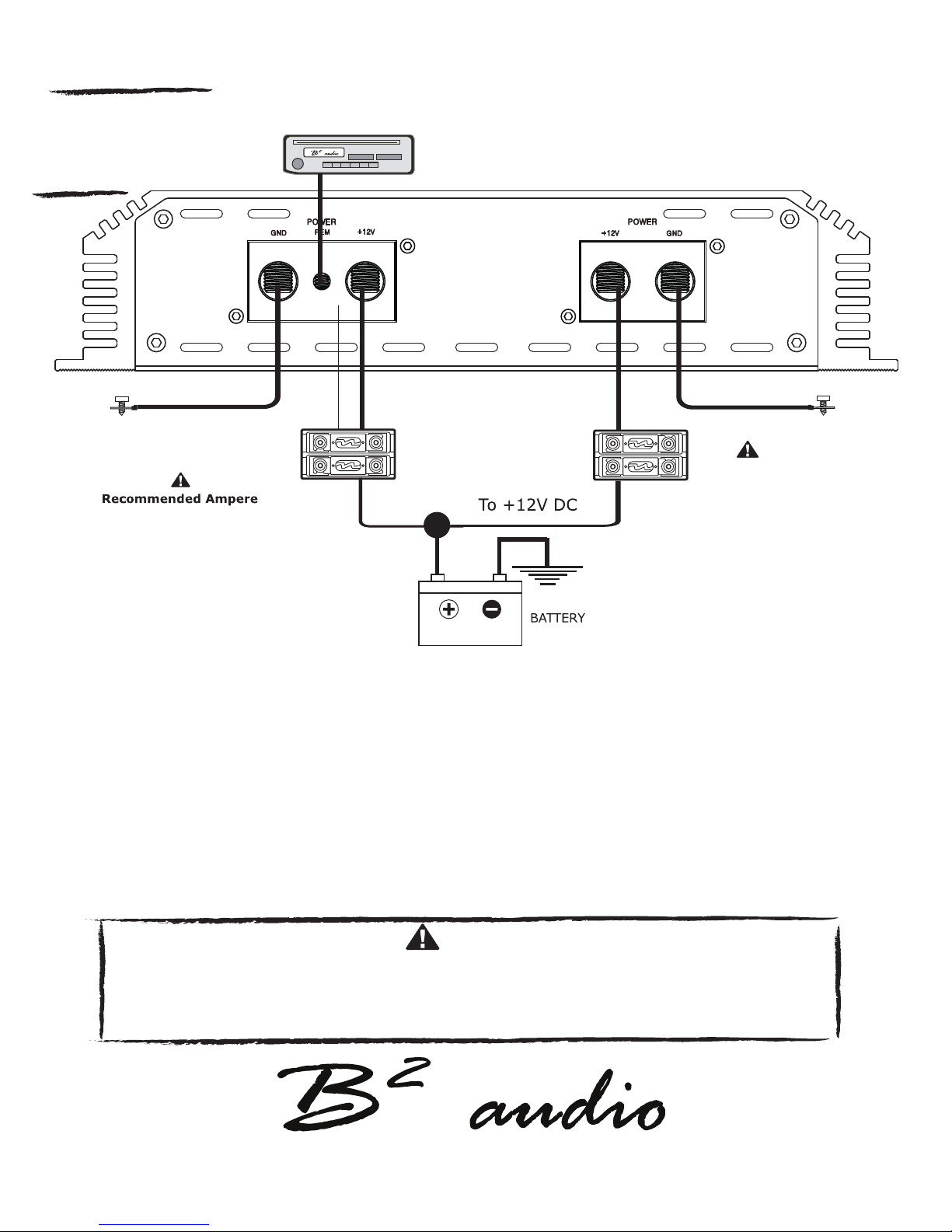
wiring layout
Zero1
Head unit
GROUND*
300A (External fuse)
GROUND*
* Keep ground as short as possible and of
equal length, no longer than 20” (50 cm).
This drawing is for illustration purpose only!
We recommend to use minumum12 Ga speaker cables to acquire the intended performance.
Run the speaker cables from your speakers to the amplier’s mounting location.
Ensure these are ran separately and away from high current cables and if possible the RCA cables as well.
In all cases where cables are penetrating the vechile’s chassis use grommets to protect the cable.
Connect the speaker wires according to the terminals on the speaker(s). Strip 3/8’’ / 1 cm of insulation of the end of
each cable and twist the cable strands together tightly. Make sure there are no stray strands that could touch other
cables or terminals as it can cause a short circut.
Crimp spade plugs over the end of the cable or tin the ends with solder to provide a solid terminal.
Connect the cable ends to the amplier as shown in the diagram. Note, the amplier’s speaker terminals are
internally bridged.
Installation of the amplifier shall be done in the following steps:
1. Connect the +12V wire, keep in mind this wire has to be fused at the battery as well. 2. Ensure the ground is
appropriate, then connect it to the amplier. 3. Connect the switched remote. 4. Reattach negative wire (ground)
to the battery. 5. Operation over 16V will cause the amplier to go into protect & can void the warranty!
CAUTION
5
Page 8
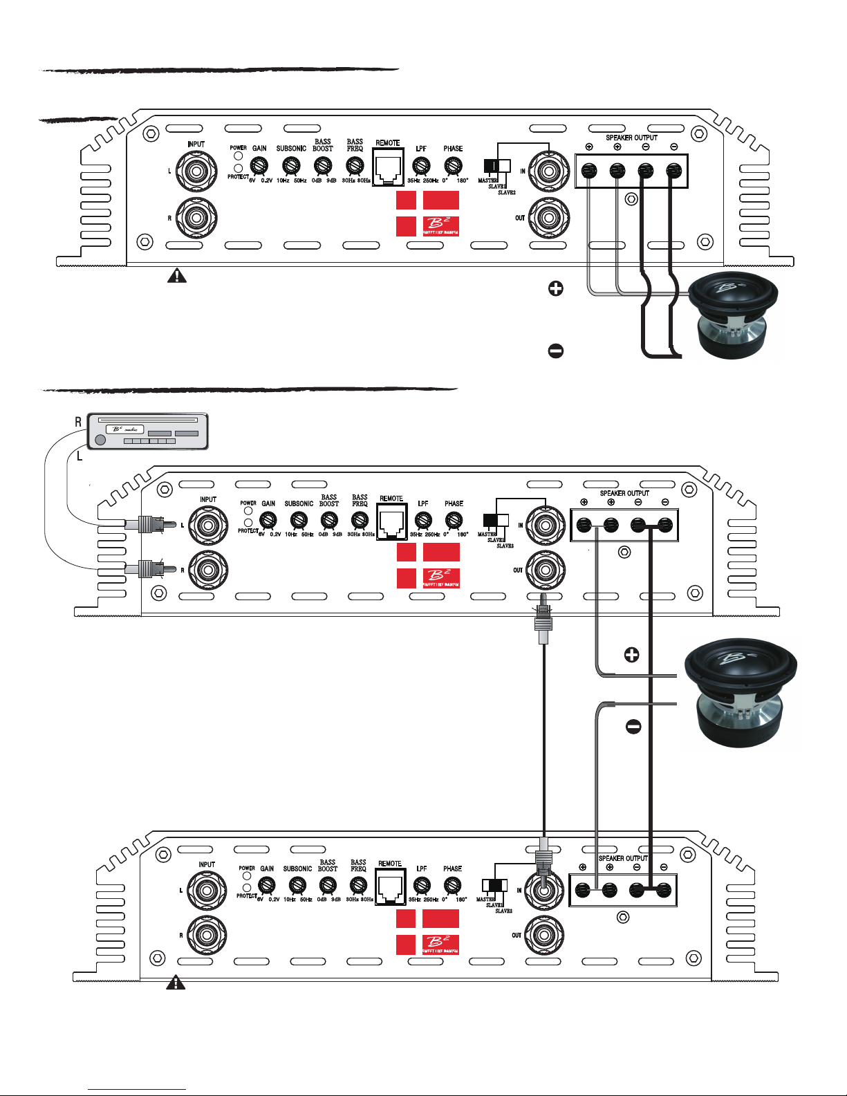
Speaker Wiring Diagram - single amplifier
zero1
BASS
BASS
BOOST
FREQ
0dB 9dB
30Hz 80Hz
Speaker impedance 1 Ohm ~ 8 Ohm
Loads under what is specied will cause excessive heat & the amplier
will reach thermal at a faster rate & will eventually go into protect.
Impedance load under 1 ohm is not warranted!
Strapped control panel setting / speaker wiring
SWEET LIKE DANISH
MASTER
SLAVE1
SLAVE2
Speaker Impedance 1~8 ohms
Head unit
MASTER AMPLIFIER
BASS
BASS
BOOST
FREQ
0dB 9dB
30Hz 80Hz
SWEET LIKE DANISH
MASTER
SLAVE1
SLAVE2
Linking or strapping makes 2 ampliers work as a single amplier. This conguration will near double the rated
output power. Follow the instructions carefully as it can cause harm to your system if done incorrect.
To enable this function, let the master amplier switch next to the phase knob stay in “OUTPUT MASTER”.
On the slave amplier, this switch shall be in “INPUT SLAVE”.
Run a RCA cable from the master amplier’s “RCA OUT”.
Connect the other end of the RCA to the slave amplier’s “RCA IN” located next to the “INPUT SLAVE” switch
SLAVE AMPLIFIER
Speaker Impedance 1~8 ohms
Speaker Impedance 2~ 8 ohms
Speaker impedance 2 Ohm ~ 16 Ohm
Loads under what is specied will cause excessive heat & the amplier
will reach thermal at a faster rate & will eventually go into protect.
Strapped impedance load under 2 ohm is not warranted!
BASS
BOOST
0dB 9dB
BASS
FREQ
30Hz 80Hz
SWEET LIKE DANISH
8
MASTER
SLAVE1
SLAVE2
Page 9
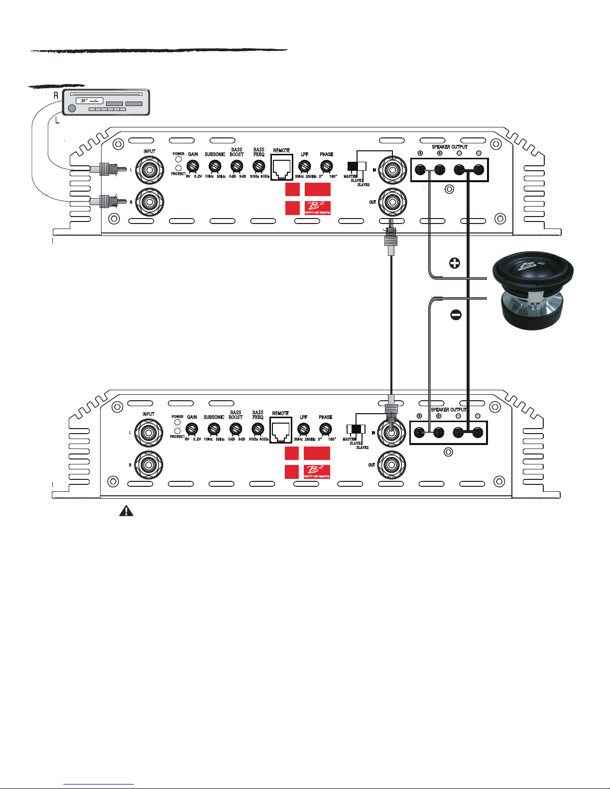
strapped Speaker Wiring master / Slave
zero1
Head unit
MASTER AMPLIFIER
BASS
BASS
BOOST
FREQ
0dB 9dB
30Hz 80Hz
SWEET LIKE DANISH
Linking or strapping makes 2 ampliers work as a single amplier. This conguration will near double the rated
output power. Follow the instructions carefully as it can cause harm to your system if done incorrect.
To enable this function, let the master amplier switch next to the phase knob stay in “OUTPUT MASTER”.
On the slave amplier, this switch shall be in “INPUT SLAVE”.
Run a RCA cable from the master amplier’s “RCA OUT”.
Connect the other end of the RCA to the slave amplier’s “RCA IN” located next to the “INPUT SLAVE” switch
MASTER
SLAVE1
SLAVE2
SLAVE AMPLIFIER
BASS
BASS
BOOST
FREQ
0dB 9dB
30Hz 80Hz
SWEET LIKE DANISH
Speaker impedance 2 Ohm ~ 16 Ohm
Loads under what is specied will cause excessive heat & the amplier
will reach thermal at a faster rate & will eventually go into protect.
Strapped impedance load under 2 ohm is not warranted!
To link the master and slave amplier speaker connection follow the steps below.
step 1.
Run the
positive terminal (+) of the subwoofer.
positive (+) speaker cable from the master amplier’s speaker output to the
MASTER
SLAVE1
SLAVE2
Speaker Impedance 2~ 8 ohms
step 2.
Run the positive (+) speaker cable from the slave amplier’s speaker output to the
negative terminal (-) of the subwoofer.
Step 3.
Connect both ampliers together by running a cable from negative speaker output on master amplier
to negative speaker output on slave amplier. Use minimum 8 GA cable for connecting the ampliers.
9
Page 10
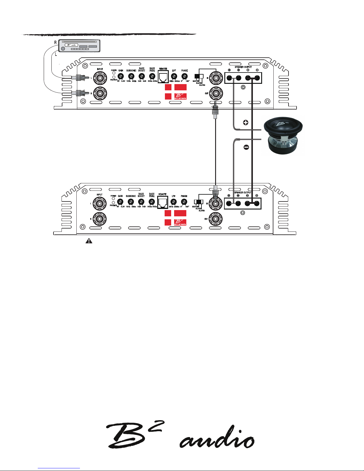
Strapped Control panel setting Master / slave 1
Head unit
MASTER AMPLIFIER
BASS
BASS
BOOST
FREQ
0dB 9dB
30Hz 80Hz
SWEET LIKE DANISH
Linking or strapping makes 2 ampliers work as a single amplier. This conguration will near double the rated
output power. Follow the instructions carefully as it can cause harm to your system if done incorrect.
To enable this function, let the master amplier switch next to the phase knob stay in “OUTPUT MASTER”.
On the slave amplier, this switch shall be in “INPUT SLAVE”.
Run a RCA cable from the master amplier’s “RCA OUT”.
Connect the other end of the RCA to the slave amplier’s “RCA IN” located next to the “INPUT SLAVE” switch
SLAVE AMPLIFIER
BASS
BASS
BOOST
FREQ
MASTER
SLAVE1
SLAVE2
Speaker Impedance 2~ 8 ohms
0dB 9dB
Speaker impedance 2 Ohm ~ 16 Ohm
Loads under what is specied will cause excessive heat & the amplier
will reach thermal at a faster rate & will eventually go into protect.
Strapped impedance load under 2 ohm is not warranted!
30Hz 80Hz
SWEET LIKE DANISH
MASTER
SLAVE1
SLAVE2
To link the master and slave 1 amplier RCA connection follow the steps below.
Keep in mind ampliers needs to be switched o, linking the ampliers when switched on may cause harm and can void your warranty!
Step 1. Connect RCA from Head Unit / output source into master amplier RCA input.
If only one output is available, then use a Y-split to connect both L & R.
Step 2. Locate the Master / Slave 1 / Slave 2 switch on the right side of the control panel on the Master amplier.
Set the switch to Master position.
step 3. Connect a single RCA from the RCA OUT on the master amplier.
Step 4. Locate the Master / Slave 1 / Slave 2 switch on the right side of the control panel on the Slave 1 amplier.
Set the switch to Slave 1 position.
Step 5. Connect the single RCA cable from the Master amplier’s Rca out to the slave 1 amplier’s single RCA IN.
10
Page 11
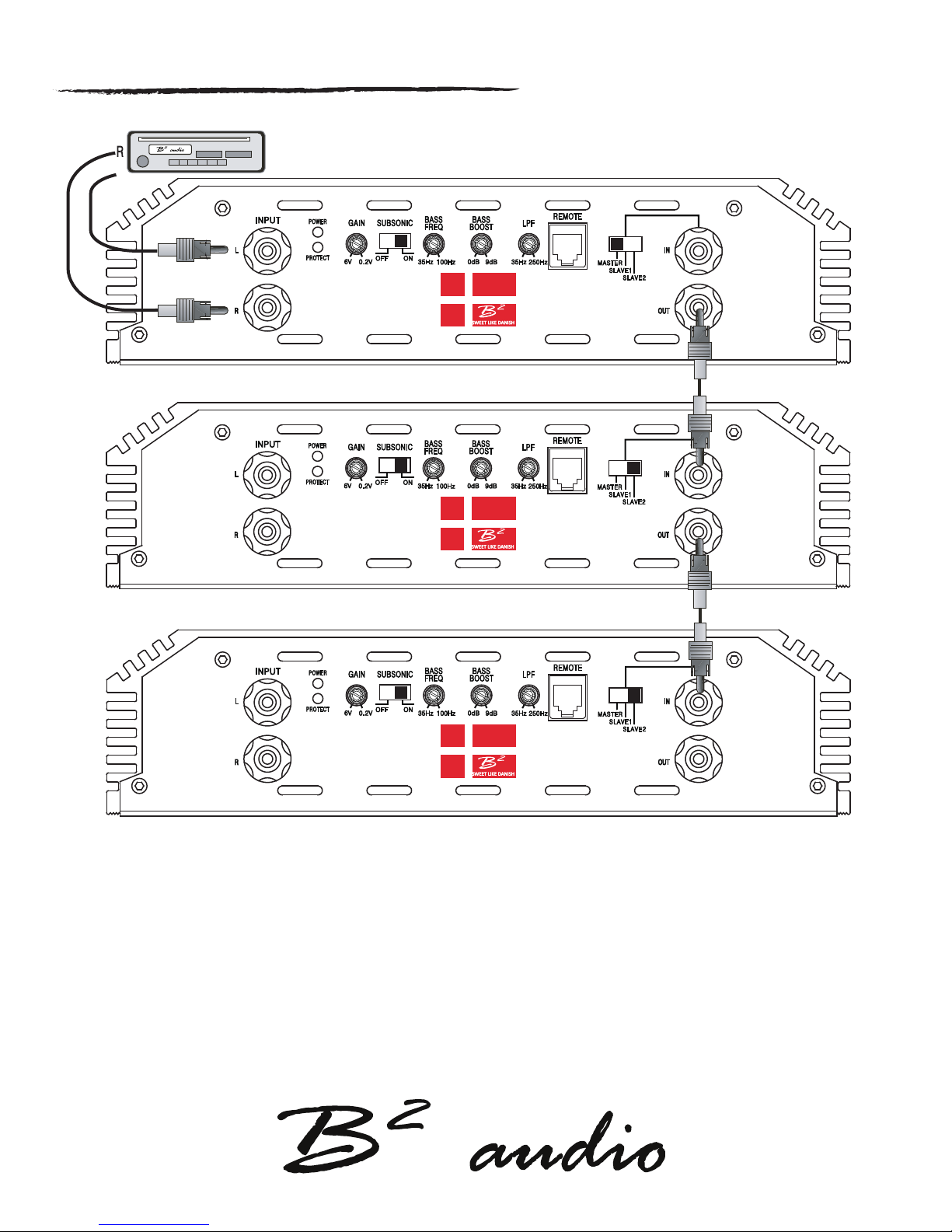
Control panel setting Master / slave 2 / SLave 2
Head unit
L
master
slave 2
slave 2
To link the master and slave 2 ampliers in daisy chain mode follow the steps below. Each slave 2 will be controlled by the master’s control panel, but
the speakers must be connected individually to each amp. The daisy chain is a true benet when you have multiple speakers and amps.
Step 1. Connect RCA from Head Unit / output source into
If only one output is available, then use a Y-split to connect both L & R.
Step 2.
step 3. Connect a single RCA from the RCA OUT
Step 4. Locate the Master / Slave 1 / Slave 2 switch on the right side of the control panel on the rst
Step 5. Connect the single RCA cable from the Master
step 6. Connect a single RCA from the RCA out on the rst slave 2 amplier & connect the other end to the second Slave 2 amplier’s RCA IN.
step 7. Set the Master / Slave 1 / Slave 2 switch on the right side of the control panel on the second Slave 2 amplifer to slave 2.
step 8. Connect the speaker(s) to each individual amp.
Locate the Master / Slave 1 / Slave 2 switch on the right side of the control panel on the Master amplier. Set the switch to Master.
master amplier RCA input.
on the master amplier.
Slave 2 amplier. Set the switch to Slave 2.
amplier’s Rca out to the rst slave 2 amplier’s single RCA IN.
11
Page 12
Troubleshooting
The protection circuits of the amplier prevents severe damages from faulty conditions & improper use.
The protection indicatior will switch on due to short circuit connection & speaker overload, thus the amplier will be turned o.
Prior to inspecting the occurred problem, turn all levels down & all power o, then carefully check the installation for
wiring mistakes, shorts or faulty ground (GND). If the amplier shuts down due to excessive heat, the protection indicator will
light up; please allow time for the unit to be cooled o. Before removing your amplier, refer to the list below and follow the
suggested procedures step by step. If not at ease, contact an authorized installer which can assist you.
AMPLIFIER DOESN’T TURN ON
Measure voltage on the +12V terminal.
Ensure that the remote terminal has min. 13.8 V DC remote connection.
Recheck the ground (GND) connection. Inspect the in-line fuses.
Check the protection LED is not on.
PROTECTION LED IS LIT ONCE THE AMPLIFIER IS TURNED ON
.
Check shorts on speaker wires & the connected load / impedance. Check power cables & GND.
Disconnect the speaker cables and reset the amplifier.
High / Low voltage, operation voltage is 9 V ~ 15 V+. Voltages below / beyond this will cause the amplifier to go into protect.
FUSE BLOWING
Measure the speaker impedance & that it is in accordance with the configuration.
Inspect the power cable for shorts along with vehicle chassis.
OVERHEATING
Measure the speaker impedance & that it is in accordance with the configuration.
Check speaker shorts.
Ensure airflow around the amplifier is sufficient & that the amplifier is not installed in
areas of excessive vibration & upside down!
AUDIO OUTPUT INSUFFICIENT - DISTORTED SOUND
Ensure that the gain settings on the amplifier is matched with the output level of the head unit.
Adjust the head unit volume.
Check speaker shorts.
Adjust the crossover frequencies in accordance with the setup.
If no output at all, check the RCA connections & the cable itself.
TURN ON THUMP
Disconnect the signal input to the amplifier, then turn it on and off.
a) If the noise is cancelled, then connect a delay turn on module on the REM wire running from
the source unit to the amplifier.
b) Use another 12V source for REM lead to the amplifier. If the noise is cancelled, use a relay
to isolate the amplifier from the turn on thump.
HIGH HISS-ENGINE NOISE IN SPEAKERS
Ensure that all signal transferring wires (RCA, speaker cables etc) are kept seperately / away from
the power and the ground wires.
Bypass all electrical components between the Head unit and the amplifier.
Connect the Head unit directly to the amplifier’s input. If the noise is eliminated, the unit bypassed
is the one causing the noise.
Remove the existing ground wires for all electrical components installed. Ensure that the point of
ground is 100% metal which has been grinded free of rust, paint etc.
Replace the ground cable from the OEM battery / alternator and ensure it is grounded accordingly.
Test the battery and alternator load (can be carried out by a professional).
Ensure that the vehichle’s electrical system is in a good condition, this includes distributor, alternator,
spark plugs / wires, voltage regulators etc.
Feel free to visit us at: www.b2audio.com / www.facebook.com/b2audio / twitter:@b2_audio / instagram: b2_audio / www.youtube.com/b2audio
13
 Loading...