

Page 1
Type 6213 EV, 6281 EV
2/2-way solenoid valve
Operating Instructions
Page 2
1 OPERATING INSTRUCTIONS
The operating instructions contain important information.
▶ Read the operating instructions carefully and follow the safety
instructions in particular, and also observe the operating conditions.
▶ Operating instructions must be available to each user.
▶ The liability and warranty for the device are void if the operating
instructions are not followed.
1.1 Symbols
▶ designates an instruction to prevent risks.
→ designates a procedure which you must carry out.
Warning of injuries:
DANGER!
Imminent danger. Serious or fatal injuries.
WARNING!
Potential danger. Serious or fatal injuries.
CAUTION!
Danger. Minor or moderately severe injuries.
Warns of damage to property:
NOTE!
2 INTENDED USE
Incorrect use of the solenoid valve can be dangerous to people,
nearby equipment and the environment.
▶ The device type 6213 EV / 6281 EV is designed to control, shut o
and meter neutral media up to a viscosity of 21 mm
▶ Provided the cable plug is connected and installed correctly, e.g.
Bürkert Type 2508, the device satises protection class IP65 in
accordance with DIN EN 60529 / IEC 60529.
▶ Use according to the permitted data, operating conditions and
conditions of use specied in the contract documents and operating instructions.
▶ In the case of explosion-proof devices (see rating plate or addi-
tional plate) also follow the operating instructions for the coil /
pilot control.
▶ Correct transportation, correct storage and installation and careful
use and maintenance are essential for reliable and problem-free
operation.
▶ Use the device only as intended.
2
/s.
2.1 Denition of term
In these operating instructions, the term “device” always refers to the
Type 6213EV / 6281EV.
2
english
Page 3
3 BASIC SAFETY INSTRUCTIONS
These safety instructions do not make allowance for any
• contingencies and events which may arise during the installation,
operation and maintenance of the devices.
• local safety regulations - the operator is responsible for observing
these regulations, also with reference to the installation personnel.
Danger - high pressure.
▶ Before loosening the pipes and valves, turn o the pressure and
vent the pipes.
Risk of electric shock.
▶ Before reaching into the device or the equipment, switch o the
power supply and secure to prevent reactivation.
▶ Observe applicable accident prevention and safety regulations
for electrical equipment.
Risk of burns/risk of re if used for a prolonged switch-on time
through hot device surface.
▶ Keep the device away from highly ammable substances and
media and do not touch with bare hands.
Risk of injury due to malfunction of valves with alternating
current (AC).
Sticking core causes coil to overheat, resulting in a malfunction.
▶ Monitor process to ensure function is in perfect working order.
Risk of short-circuit/escape of media through leaking screw
joints.
▶ Ensure seals are seated correctly.
▶ Carefully screw valve and pipelines together.
To prevent injury, ensure that:
▶ Do not make any external modications to the housing of the
device. Ensure that the system cannot be activated unintentionally.
▶ Installation and repair work may be carried out by authorized
technicians only and with the appropriate tools.
▶ After an interruption in the power supply or uidic supply, ensure
that the process is restarted in a dened or controlled manner.
▶ Do not put any loads on the body.
▶ The general rules of technology apply to application planning
and operation of the device.
english
3
Page 4
3.1 Warranty
2 (A)
1 (P)
2 (B)
1 (P)
The warranty is only valid if the device is used as intended in accor-
dance with the specied application conditions.
3.2 Information on the internet
The operating instructions and data sheets for type 6213 EV / 6281EV
can be found on the internet at:
www.buerkert.com
Type “6213” or “6281”
4 TECHNICAL DATA
4.1 Operating conditions
The following values are indicated on the type label:
• Voltage (Tolerance ± 10 %) / Current type
• Coil power consumption
(active power in W - at operating temperature)
• Operating pressure
• Body material: Brass (MS), Stainless steel (VA)
• Seal material: FKM, EPDM, NBR
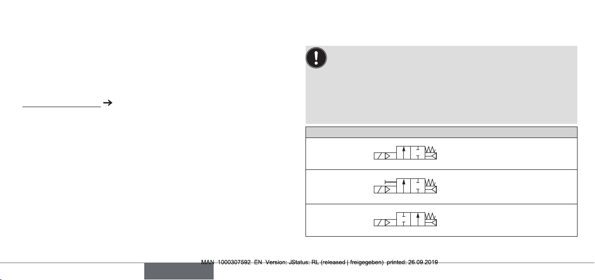
Circuit function:
A (NC)
2 (A)
A (NC)
1 (P)
2/2-way valve, normally
closed
2/2-way valve, normally
closed,
with manual override
B (NO)
2/2-way valve, normally
open
Protection class: IP65 with accordance with DIN EN 60529 / IEC
4
english
60529 with cable plug, e. g. Bürkert Type 2508
Page 5

Special instructions for valves circuit function B (NO) with
deaeration connection G1/8 on the coil (CF05/MX62):
The deenergized valve is open. The
medium also ows o via the deaeration
connection on the coil.
Valves of this design are therefore
suitable for relieving compressors only.
4.2 Application conditions
Ambient temperature: max. +55°C
Operating duration: Unless otherwise indicated on the type
label, the solenoid system is suitable for
continuous operation
Important information for functional reliability during continuous operation.
If standstill for a long period at least 1-2 activations per day
are recommended.
Service life: High switching frequency and high pres-
sures reduce the service life
Permitted medium temperature depending on coil and seal material:
Coil body
PA/EP
1)
Seal material Medium temperature
Polyamide PA FKM 0...+90°C
Epoxy EP (NA38) FKM 0...+120°C
Polyamide PA EPDM -30...+90°C
Epoxy EP (NA38) EPDM -30...+100°C
Polyamide PA NBR -10...+80°C
1) Marking PA and EP under electric connection
Permitted media depending on seal material:
Seal material Permitted media
2)
FKM Per-solutions, hot oils without additives, diesel
and heating oil without additives, detergent
solution
EPDM Oil and grease-free liquids, cold and warm
water
NBR Cold and warm water
2)
Gaseous media at low dierential pressures (e.g. compressed air and vacuum)
can also be actuated in consideration (or due to restriction) of a lower
tightness. We recommend prior clarication with our sales oce regarding
the possible application
english
5
Page 6
The following values must also be observed for valves with
6213EV A 10 EPDM MS
UL/UR approval:
Non-hazardous
uids (air and inert
gas)
Medium
temperature
-30...+120°C
-30...+100°C
(for 6213 DN40)
Ambient
temperature
-30...+55 °C
Water 0...+100°C 0...+55 °C
Fire protection
+5...+90 °C +5...+55 °C
service valve (PE48)
4.3 Conformity
In accordance with the EU Declaration of conformity, the solenoid
valve Type 6213 EV / 6281 EV is compliant with the EU Directives
(if applicable).
4.4 Standards
The applied standards, which verify conformity with the EU Directives,
can be found on the EU Type Examination Certicate and / or the EU
Declaration of Conformity (if applicable).
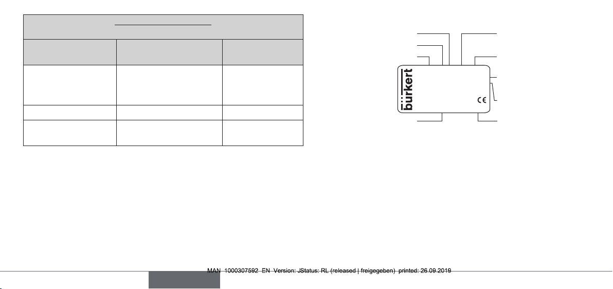
4.5 Type label (Example)
Orice Seal material
Circuit function
Typ e
G3/8 P
N0 -
10bar
W14 LU
Identication number
230V 50Hz 8W
Made in Germany
00221649
Body material
Connection thread,
operating pressure
Voltage, Frequency,
Power consumption
Manufacturer code
6
english
Page 7
5 INSTALLATION
5.1 Safety instructions
DANGER!
Risk of injury from high pressure in the equipment.
▶ Before loosening the pipes and valves, turn o the pressure and
vent the pipes.
Risk of injury due to electrical shock.
▶ Before reaching into the system, switch o the power supply
and secure to prevent reactivation.
▶ Observe applicable accident prevention and safety regulations
for electrical equipment.
WARNING!
Risk of injury from improper installation.
▶ Installation may be carried out by authorized technicians only
and with the appropriate tools.
Risk of injury from unintentional activation of the system and an
uncontrolled restart.
▶ Secure system from unintentional activation.
▶ Following installation, ensure a controlled restart.
5.2 Before installation
Installation position: any, actuator preferably upwards.
Procedure:
→ Check pipelines for dirt and clean.
→ Install a dirt lter before the valve inlet (≤ 500 µm).
5.3 Installation
NOTE!
Caution risk of breakage.
▶ Do not use the coil as a lifting arm.
→ Hold the device with a open-end wrench on the body and screw
into the pipeline.
→ Observe direction of ow:
The arrow on the body indicates the direction of ow.
english
7
Page 8

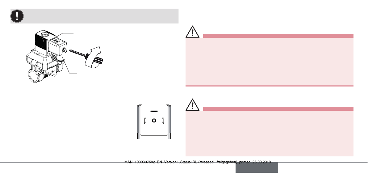
5.4 Manual override
(optional Type 6281, Code HA15/HA17)
To control the valve manually, the hand lever under the coil must be
turned into the vertical position.
NOTE!
Caution.
▶ Do not overturn hand lever.
▶ When the hand lever is actuated, the valve can no longer be
switched electrically.
HA15
Opened position
Hand lever
HA17
Opened position
5.5 Electrical connection of the cable plug
WARNING!
Risk of injury due to electrical shock.
▶ Before reaching into the system, switch o the power supply
and secure to prevent reactivation.
▶ Observe applicable accident prevention and safety regulations
for electrical equipment.
If the protective conductor contact between the coil and body is
missing, there is danger of electrical shock.
▶ Always connect protective conductor.
▶ Check electrical continuity between coil and body.
Procedure:
→ Tighten cable plug (for permitted types see data sheet), observing
max. torque 1 Nm.
→ Check that seal is tted correctly.
→ Connect protective conductor and check electrical continuity
between coil and body.
Closed position
8
english
Closed position
Page 9
Note the voltage and current type as specied on the type
label.
Seal
max. 1 Nm
Authorized cable plug e.g. Type 2508 or
other suitable cable plug in accordance
with DIN EN 175301-803 Form A
Pulse version (optional, Code CF 16):
• Valve opens when current pulse min. 50 ms:
– on Pin 1, + on Pin 2
• Valve closes when current pulse min. 50 ms:
+ on Pin 1, – on Pin 2
6 MAINTENANCE, TROUBLESHOOTING
6.1 Safety instructions
WARNING!
Risk of injury from improper maintenance.
▶ Maintenance may be carried out by authorized technicians only
and with the appropriate tools.
Risk of injury from unintentional activation of the system and an
uncontrolled restart.
▶ Secure system from unintentional activation.
▶ Following maintenance, ensure a controlled restart.
6.2 Installation of the coil
WARNING!
Risk of injury due to electrical shock.
2
1
▶ Before reaching into the system, switch o the power supply and
secure to prevent reactivation.
▶ During installation ensure that the coil is situated rmly on the
body cover so that the protective conductor connection of the
coil is connected to the valve body.
▶ Check protective conductor contact after installing the coil.
english
9
Page 10

Escaping medium.
When a sticking nut is loosened, medium may escape.
▶ Do not tighten sticking nut any further.
Overheating, risk of re.
Connection of the coil without pre-assembled valve will result in
overheating and destroy the coil.
▶ Connect the coil with pre-assembled valve only.
Procedure:
→ Connect coil body to the core guide pipe.
→ Screw on coil with nut. Observe torque.
NOTE!
Device will be damaged if the wrong tools are used.
Always use a wrench to tighten nut. If other tools are used (e.g.
pliers), the device may be damaged.
→ Check protective conductor.
Nut
Core guide pipe
O-ring
Locking pin
+
Torque for fastening nut:
Coil type Coil width Torque
AC10 32 mm resp. 40 mm 5 Nm
AC19 42 mm 10 Nm
Observe
torque for
fastening nut
(See table) !
10
english
Page 11
6.3 Malfunctions
If malfunctions occur, check whether:
→ the device has been installed according to the instructions,
→ the electrical and uid connections are correct,
→ the device is not damaged,
→ all screws have been tightened,
→ the voltage and pressure have been switched on,
→ the pipelines are clean.
Valve does not switch
Possible cause:
• Short circuit or coil interrupted.
• Core or core area dirty.
• Medium pressure outside the permitted pressure range.
Valve does not close
Possible cause:
• Internal space of the valve is dirty.
• Small control bore in the diaphragm blocked.
• Valve opened by manual control.
7 SPARE PARTS
CAUTION!
Risk of injury and/or damage by the use of incorrect parts.
Incorrect accessories and unsuitable spare parts may cause injuries
and damage the device and the surrounding area.
▶ Use only original accessories and original spare parts from
Bürkert.
7.1 Ordering spare parts
Replacement part sets
When ordering replacement part sets, quote the sets SET 1, SET 3 or
SET 7 and the identication number of the device.
english
11
Page 12

7.2 Overview of replacement part sets
6213 EV
Coil set
SET 1
6281 EV
Coil set
SET 1
6281 EV (MX62)
Compressor relief valve NO
Coil set
SET 1
Plunger tube
Wearing
parts set
SET 3
The composition of the spare part sets may dier from the diagram
depending on the model of valves.
12
english
set SET 7
Wearing
par
ts set
SET 3
Plunger tube set
SET 7
Wearing parts set
SET 3
Page 13

8 TRANSPORT, STORAGE, DISPOSAL
NOTE!
Transport damages.
Inadequately protected equipment may be damaged during
transport.
▶ During transportation protect the device against wet and dirt in
shock-resistant packaging.
▶ Avoid exceeding or dropping below the allowable storage
temperature.
Incorrect storage may damage the device.
▶ Store the device in a dry and dust-free location.
▶ Storage temperature: -40...+80°C.
Damage to the environment caused by device components
contaminated with media.
▶ Observe applicable regulations on disposal and the
environment.
→ Dispose of the device and packaging in an environmentally
friendly manner.
english
13
Page 14

Bürkert Fluid Control Systems
Sales Center
Christian-Bürkert-Str. 13-17
D-74653 Ingelfingen
Tel. + 49 (0) 7940 - 10 91 111
Fax + 49 (0) 7940 - 10 91 448
E-mail: info@burkert.com
International address
www.burkert.com
Manuals and data sheets on the Internet: www.burkert.com
Bedienungsanleitungen und Datenblätter im Internet: www.buerkert.de
Instructions de service et fiches techniques sur Internet : www.burkert.fr
© Bürker t Werke GmbH & Co. KG, 2013-2019
Operating Instructions 1909/11_EU-ML_0 0805875 / Original DE
www.burkert.com
 Loading...