

Page 1
www.burkert.com
We reserve the right to make
technical changes without notice.
Technische Änderungen
vorbehalten.
Sous réserve de modifications
techniques.
© Bürkert SAS, 2011-2014
Operating Instructions
1408/01_EU-ml_00563282_Original_FR
Types 1078-1 / 1078-2
Timer without or with configuration module type 1077-2
Operating Instructions
Bedienungsanleitung
Manuel utilisateur
2
1. ABOUT THIS MANUAL ...........................................................3
2. INTENDED USE ..........................................................................5
3. BASIC SAFETY INFORMATION .........................................7
4. GENERAL INFORMATION .................................................. 10
5. AREA OF APPLICATION ......................................................11
6. TECHNICAL DATA .................................................................. 15
7. INSTALLATION AND WIRING ........................................... 20
8. COMMISSIONING .................................................................. 23
9. ADJUSTMENT ........................................................................... 25
10. MAINTENANCE AND TROUBLESHOOTING ............ 41
11. SPARE PARTS AND ACCESSORIES ........................... 42
12. PACKAGING, TRANSPORT ............................................... 43
13. STORAGE ................................................................................... 43
14. DISPOSAL OF THE DEVICE .............................................44
English
3
1. ABOUT THIS MANUAL
This manual describes the entire life cycle of the device.
Please keep this manual in a safe place, accessible to all
users and any new owners.
This manual contains important safety information.
Failure to comply with these instructions can lead to
hazardous situations.
• This manual must be read and understood.
1.1. Symbols used
danger
Warns you against an imminent danger.
• Failure to observe this warning can result in death or in
serious injury.
Warning
Warns you against a potentially dangerous situation.
• Failure to observe this warning can result in serious
injury or even death.
English
3
Page 2
4
caution
Warns you against a possible risk.
• Failure to observe this warning can result in substantial
or minor injuries.
note
Warns you against material damage.
• Failure to observe this warning may result in damage
to the device or system.
indicates additional information, advice or
important recommendations.
refers to information contained in this manual or in
other documents.
→ indicates a procedure to be carried out.
1.2. Definition of the word "device"
The term "device" used within the manual refers to the
timer type 1078-1 or 1078-2 (with or without configuration
module type 1077-2).
English
5
2. INTENDED USE
Use of the timer that does not comply with the
instructions could present risks to people, nearby
installations and the environment.
• The timer, with or without configuration module, allows
for controlling the activation/deactivation cycle of a
solenoid valve having a compatible supply voltage.
• Installation, adjustment and maintenance of the device
must be carried out by qualified staff with an electrical
certification for the 110/230 V AC energized versions.
• Protect the device from electromagnetic perturbations,
ultraviolet radiations and, when installed outside, from
the effects of climatic conditions.
• Use this device in compliance with the characteristics
and commissioning and use conditions specified in the
contractual documents and in the instruction manual.
• Requirements for safe and proper operation are proper
transport, storage and installation as well as careful
operation and maintenance.
• Only use the device as intended.
2.1. Restraints
Observe any existing restraints when the device is exported.
English
6
2.2. Foreseeable misuse
• Do not use this device in a potentially explosive atmosphere.
• Do not subject the device to mechanical loads (e.g. by
placing objects on top of it or by using it as a step).
• Do not make any external modifications to the device. Do
not paint or varnish any part of the device.
English
7
3. BASIC SAFETY INFORMATION
This safety information does not take into account:
• any contingencies or occurences that may arise during
assembly, use and maintenance of the devices.
• the local safety regulations that the operator must ensure
the staff in charge of assembly observe.
danger
Danger due to electrical voltage.
• Shut down the electrical power source of all the conductors and isolate it before carrying out work on the
system.
English
7
Page 3
8
Various dangerous situations
To avoid injury take care to:
• prevent any accidental power supply switch-on.
• carry out installation and maintenance by qualified and
skilled staff with the appropriate tools.
• guarantee a defined or controlled restarting of the
process, after a power supply interruption.
• use the device only if in perfect working order and in
compliance with the instructions provided in the user
manual.
• observe the general technical rules during the planning
and use of the device.
English
9
note
Elements / Components sensitive to electrostatic
discharges
• This device contains electronic components sensitive
to electrostatic discharges. They may be damaged
if they are touched by an electrostatically charged
person or object. In the worst case scenario, these
components are instantly destroyed or go out of order
as soon as they are activated.
• To minimise or even avoid all damage due to an electrostatic discharge, take all the precautions described
in the EN 61340-5-1 norm.
• Also ensure that you do not touch any of the energized
electrical components.
English
9
10
4. GENERAL INFORMATION
4.1. Manufacturer's address and
international contacts
To contact the manufacturer of the device, use following
address:
Bürkert SAS
Rue du Giessen
BP 21
F-67220 TRIEMBACH-AU-VAL
The addresses of our international branches can be found
on the last pages of this manual.
They can also be found on the Internet under:
www.burkert.com
4.2. Warranty conditions
The condition governing the legal warranty is the conforming use of the device in observance of the operating
conditions specified in this manual.
4.3. Information on the Internet
You can find the user manual and technical datasheets
regarding type 1078 or 1077 on the internet at:
www.burkert.com
English
11
5. AREA OF APPLICATION
The timer 1078-1 or 1078-2 is plugged on a solenoid valve
by means of an EN 175301-803 form A fixed connector.
The timer allows for controlling the activation/deactivation
cycle of the solenoid valve.
5.1. General description
5.1.1. Construction
The timer 1078-1 or 1078-2 is a class II control device and
a Type 1 action device (see EN 60730-1 standard).
The timer 1078-1 or 1078-2 is an electronic module enclosed
in a housing with a transparent cover, a cable gland and an
EN 175301-803 female fixed connector, form A, with seal.
The timer is attached to the solenoid valve by means of a
screw.
• The timer 1078-1 is connected to the power supply
through the cable gland, by means of a 3-pole terminal
block in the housing.
• The timer 1078-2 is connected to the power supply
through the cable gland, by means of a 5-pole terminal
block in the housing.
The timer energizes the solenoid valve.
The timer 1078-2 can be configured by means of a configu-
ration module 1077-2, inserted onto the 1078-2 in place of
English
11
Page 4
12
its cover.
5.2. Available versions
Device Supply voltage Order code
Timer 1078-1
12-24 V DC 060647
24-48 V AC, 50-60 Hz,
24-48 V DC
060621
110-230 V AC,
50-60 Hz
060620
Timer 1078-2
12-24 V DC 060648
24-48 V AC, 50-60 Hz,
24-48 V DC
060629
Configuration module 1077-2 for timer
1078-2
060638
English
13
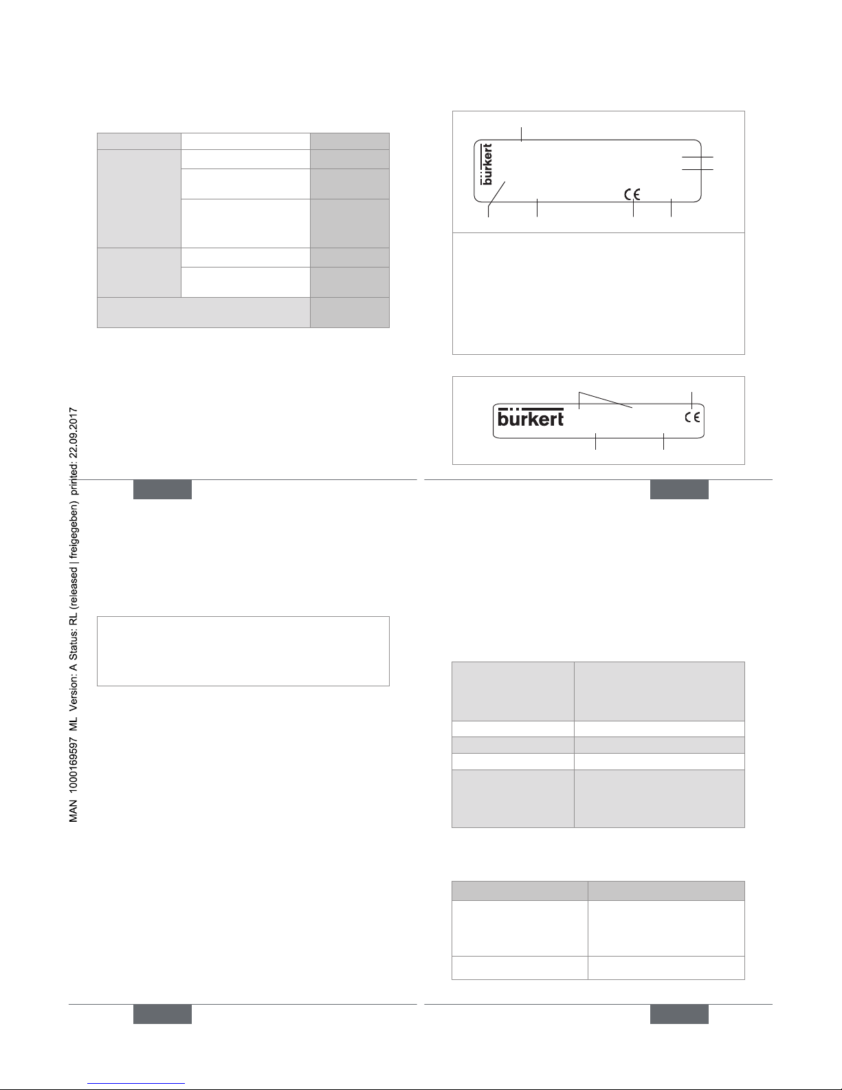
5.3. Description of the name plates
1078-1
Supply: 110-230V/50-60Hz 0,5A
Output: 110-230V/50-60Hz 0,5A
S/N 1000
00060620 W43ML
Made in France
1
2
3
6 5 47
1. Type of the device
2. Power supply data
3. Data of the power supplied to the solenoid valve
4. Construction code
5. Conformity logo
6. Order code
7. Serial number
Fig. 1: Nameplate of the 1078
1077-000-00-002-000-000
00060638 W45LP
Made in France
1 2
4 3
English
13
14
1. Type of the device
2. Conformity logo
3. Construction code
4. Order code
Fig. 2: Nameplate of the 1077
English
15
6. TECHNICAL DATA
6.1. Conditions of use
Ambient temperature
• 1078
• 1077
(in operation)
• -10°C...60°C
• 0°C...60°C
Air humidity < 85%, non condensated
Height above sea level max. 2000 m
Degree of pollution 2
Protection rating IP65, when screwed to the
solenoid valve at a torque rating
between 0,5 and 0,8 Nm, wired
and cable gland tightened
6.2. General technical data
6.2.1. Mechanical data
Part Material
Housing
• 1078
• 1077-2
• PA6 or polyarylamide
• Polyamide
Cover PSU
English
15
Page 5
16
Part Material
Female EN 175301-803
fixed connector
PA6
PG9 cable gland PA6 or polyarylamide
M3x45 or M3x55 screw 1, in stainless steel AL2
Seal for the female fixed
connector
NBR
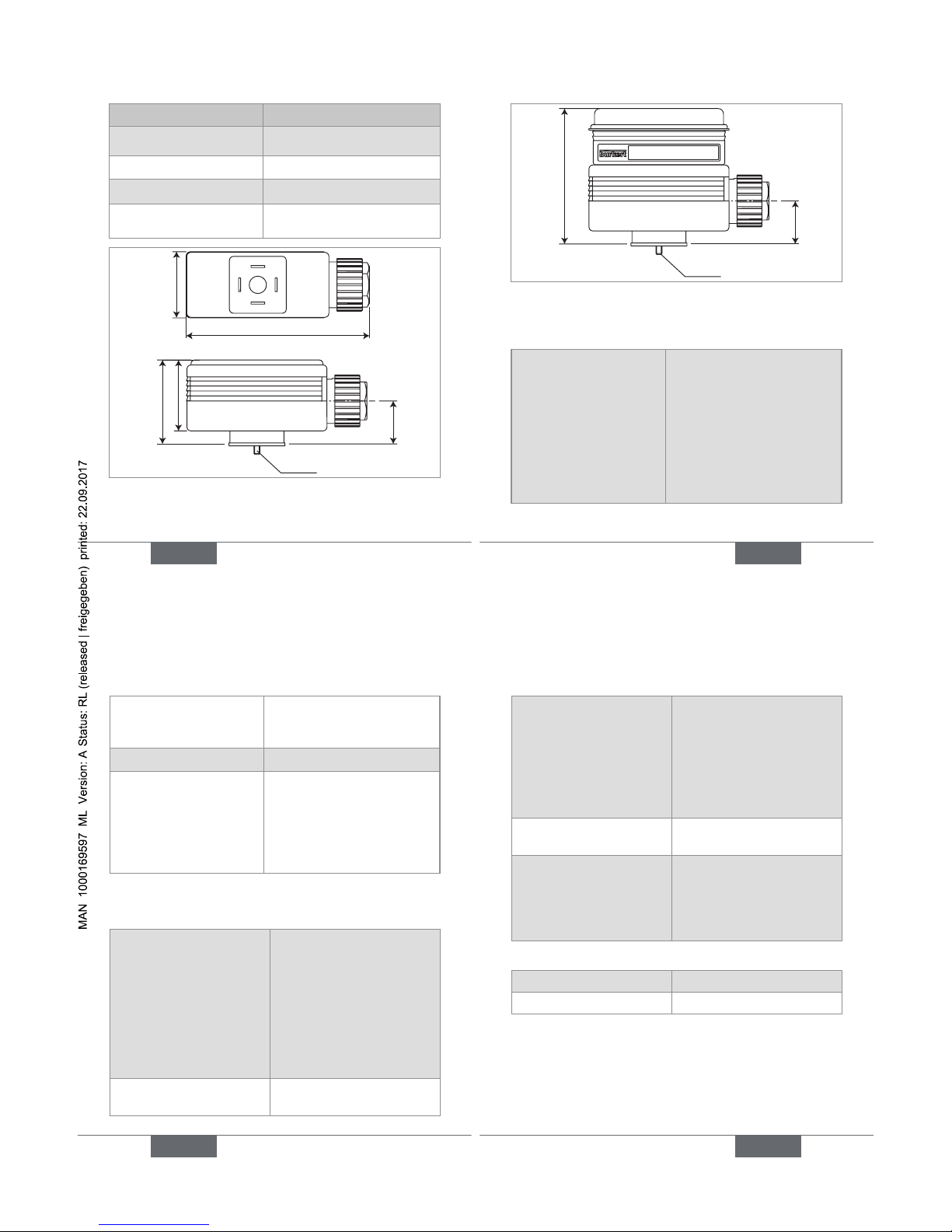
32,5
90
M3x45
42,5
36
21
Fig. 3: Dimensions [mm] of the 1078
English
17
53,5
21
M3x55
Fig. 4: Dimensions [mm] of the 1078-2 combined with
the 1077-2
6.2.2. General features
Time range (1078-1)
(mechanical adjustment
using the 6 switches N°
1, 2, 3, 6, 7 and 8)
• 0,5 to 10 s (default setting)
• 1,5 to 30 s
• 5 to 100 s
• 0,5 to 10 min.
• 1,5 to 30 min.
• 5 to 100 min.
• 12 to 240 min.
• 0,5 to 10 h
English
17
18
Time range (
1078-2)
(digital adjustment through
module 1077-2)
0,2 s to 9999 h, continuous
Tolerance (1078-2) 1 %
Resolution (1078-2)
• up to 199 s
• up to 199 min.
• up to 99 h
• up to 9999 h
• 10 ms
• 1 s
• 1 min.
• 1 h
6.2.3. Electrical data
Table 1: Electrical data of the 1078
Power supply
• 1078-1
• 1078-2
Tolerance 10 %
• 12-24 V DC, max. 2 A
or 24-48 V AC/DC, max
1,5 A or 110/230 V AC,
max 0,5 A
• 12-24 V DC, max. 2 A
or 24-48 V AC/DC, max
1,5 A
Protection against polarity
reversal
No, for devices energized
with a direct voltage
English
19
Power supplied to the
solenoid valve
• Version 12-24 V DC
• Version 24-48 V AC/DC
• Version 110/230 V AC
• 12-24 V DC, max. 2 A
• 24-48 V DC, max. 1,5 A
• 110/230 V DC, max.
0,5 A
Clearance and leakage
path
Acc. to VDE 0100
Electrical connection
• Cable diameter
• Cross section of the
wires
Through PG9 cable gland
• 6 to 7 mm
• max. 1,5 mm
2
Table 2: Electrical data of the 1077-2
Supply voltage Energized by the 1078-2
Power consumed 5 mW
English
19
Page 6
20
7. INSTALLATION AND WIRING
7.1. Safety information
danger
Risk of injury due to electrical voltage.
• Shut down the electrical power source of all the conductors and isolate it before carrying out work on the
system.
• Do not unscrew the cover of a powered device.
• Observe all applicable accident protection and safety
guidelines for electrical equipment.
Warning
Risk of injury due to nonconforming installation.
• The electrical installation can only be carried out by
qualified and skilled staff with the appropriate tools.
• Install appropriate safety devices (correctly rated fuse
and/or circuit-breaker).
English
21
Warning
Risk of injury due to unintentional switch on of power
supply or uncontrolled restarting of the installation.
• Take appropriate measures to avoid unintentional activation of the installation.
• Guarantee a defined or controlled restarting of the
process subsequent to any intervention on the device.
Protect the power supply.
• Fit the power supply with a fuse of a value suited
to the load to be switched, if it is not protected
by default.
• Use a shielded cable with an operating temperature > +80 °C.
• Use a high quality electrical power supply,
filtered and regulated.
→ Loosen the screw of the housing cover.
→ Remove the cover.
→ Loosen the nut of the cable gland.
→ Insert the cable through the nut then through the cable
gland and refer to Fig. 5 or Fig. 6 for wiring.
→ Tighten the cable gland.
English
21
22
→ Install the cover and check for the correct position of
the seal.
→ Tighten the supplied screw at a torque rating between
0,5 and 0,8 Nm.
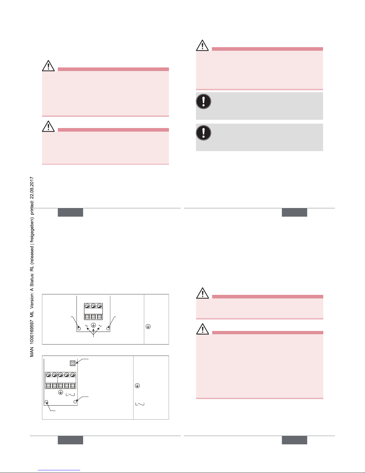
Connection of the power supply
Red LED: ON
during t
on
and
OFF during t
off
Red LED:
ON when
the device is
energized
(+) (-)
(+): V+
(-): 0V
: Protec-
tive earth
Fig. 5: Terminal assignment of the 1078-1
Connection of the
configuration module
1077-2
Red LED: ON when the
device is energized
Red LED: ON during t
on
and OFF during t
off
(+) (-)
Reset
(+): Power supply
(-): Power supply
: Protective
earth
Reset
: Binary input
(ON/OFF contact)
Fig. 6: Terminal assignment of the 1078-2
English
23
8. COMMISSIONING
8.1. Safety information
danger
Risk of electric shock.
• When the device is switched on, the cover must be
closed.
Warning
Danger due to nonconforming commissioning.
Nonconforming commissioning could lead to injuries and
damage the device and its surroundings.
• Before commissioning, make sure that the staff in
charge have read and fully understood the contents of
the manual.
• In particular, observe the safety recommendations and
intended use.
• The device/installation must only be commissioned by
suitably trained staff.
English
23
Page 7
24
note
Risk of damage to the device due to the environment
• Protect the device from electromagnetic perturbations,
ultraviolet radiations and, when installed outside, from
the effects of climatic conditions.
English
25
9. ADJUSTMENT
9.1. Safety information
danger
Risk of injury due to electrical voltage
• Observe all applicable accident protection and safety
guidelines for electrical equipment.
• For the versions fed with 110-230 V AC power supply, shut down the electrical power source of all the
conductors and isolate it before carrying out work on
the system.
Warning
Risk of injury due to nonconforming adjustment.
Nonconforming adjustment could lead to injuries and
damage the device and its surroundings.
• The operators in charge of adjustment must have read
and understood the contents of this manual.
• In particular, observe the safety recommendations and
intended use.
• The device/installation must only be adjusted by suitably trained staff.
English
25
26
9.2. Adjustment of the 1078-1
danger
Risk of electric shock on a version fed with
110-230 V AC power supply.
• To adjust the potentiometers, use an insulated
screwdriver.
note
Risk of damage the electronic board
• To adjust the potentiometers, use an insulated
screwdriver.
The set operation mode starts when the device is
energized.
• Set the operation mode before energizing the
device combined with a solenoid valve.
To adjust the 1078-1:
→ Adjusting the valve operation mode.
English
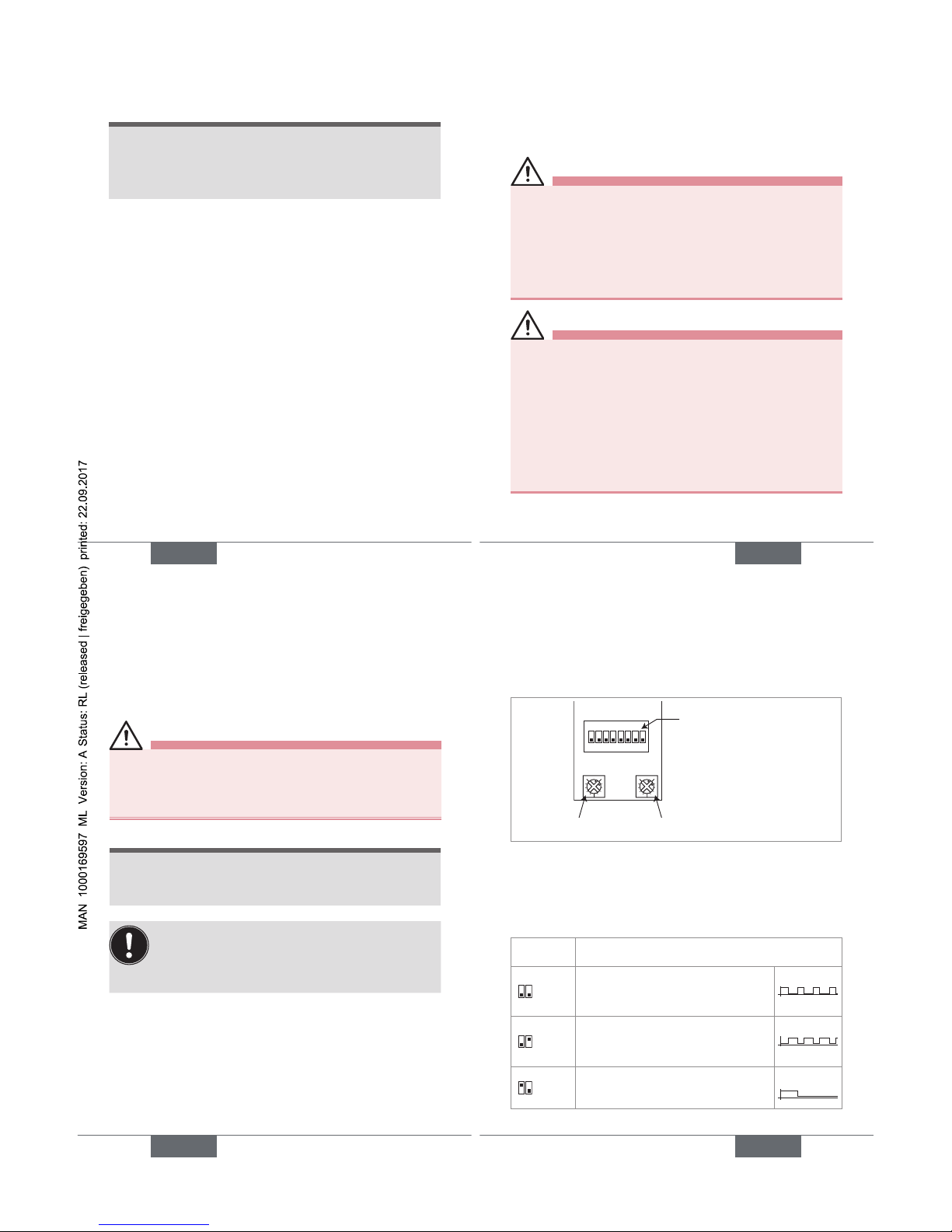
27
Switches 4 and 5: To choose the
operating mode of the solenoid
valve
Switches 1, 2 and 3: To adjust the
range t
on
.
Switches 6, 7 and 8: To adjust the
range t
off
.
Potentiometer t
off
Potentiometer t
on
1ON2345678
13
13
Fig. 7: Adjustment elements of the 1078-1
The timer 1078-1 allows for controlling the ON (called t
on
) /
OFF (called t
off
) cycle of a solenoid valve.
Four operation modes can be set with switches 4 and 5.
See Fig. 7 and Fig. 8.
Switches 4
and 5
Operation mode of the solenoid valve
4ON5
ON (ton)/OFF (t
off
) cycle of the valve: Set the
time ton and the time t
off
T
on
T
off
4ON5
OFF (t
off
)/ON (ton) cycle of the valve: Set the
time ton and the time t
off
T
on
T
off
4ON5
Timed-out activation of the valve: Only set
the time t
on
T
on
T
off
English
27
Page 8
28
Switches 4
and 5
Operation mode of the solenoid valve
4ON5
Delayed activation of the valve: Only set the
time delay t
off
T
on
T
off
Fig. 8: Operation modes of the 1078-1
→ Set the time range for t
on
with switches 1, 2 and 3 and/
or t
off
with switches 6, 7 and 8. See Fig. 7 and Fig. 9.
Switches 1, 2, 3 (ton) and 6, 7, 8 (t
off
)
Time range
1
ON
23
678
0,5-10 seconds
1
ON
23
678
1,5-30 seconds
1
ON
23
678
5-100 seconds
1
ON
23
678
0,5-10 minutes
1
ON
23
678
1,5-30 minutes
English
29
Switches 1, 2, 3 (ton) and 6, 7, 8 (t
off
)
Time range
1
ON
23
678
5-100 minutes
1
ON
23
678
12-240 minutes
1
ON
23
678
0,5-10 hours
Fig. 9: Time ranges for ton and t
off
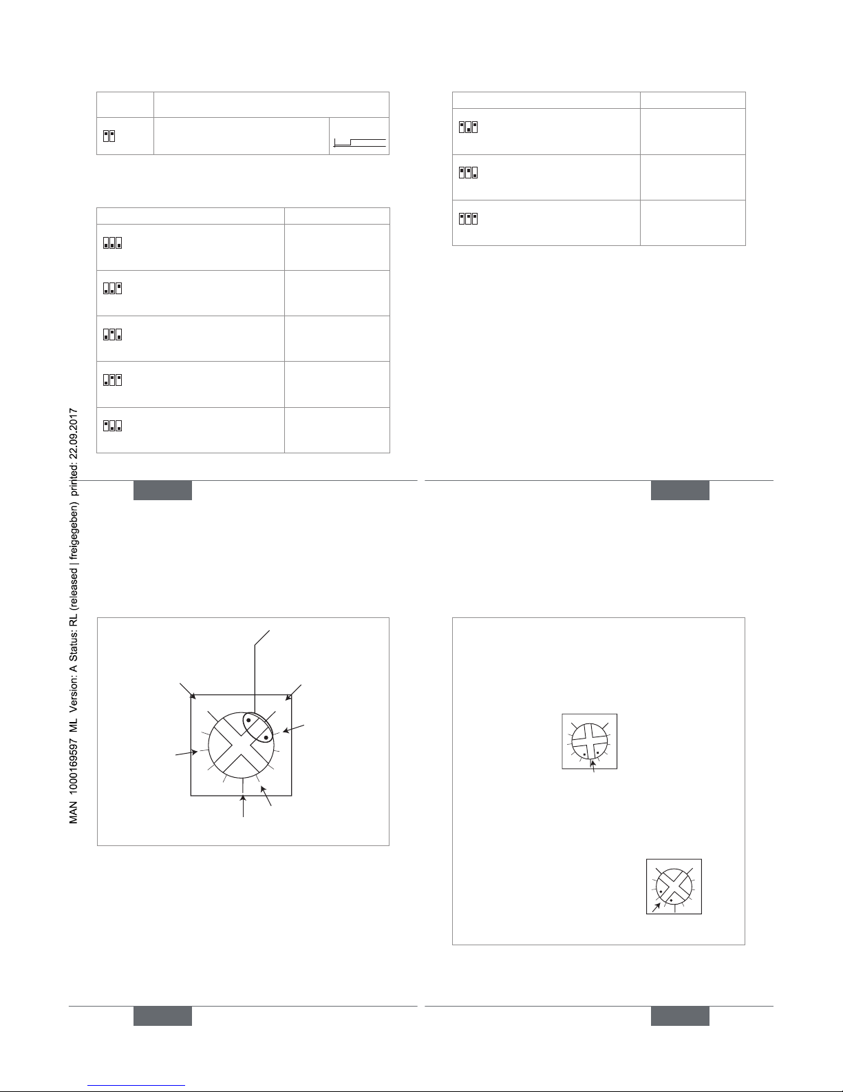
→ Set the ON time t
on
with potentiometer ton and/or the
OFF time t
off
with potentiometer t
off
, with a flat screw-
driver of correct size. See Fig. 7 and Fig. 10.
English
29
30
13
Position 1 of the potentiometer = minimum value
of the selected time range
(default position)
Position 3 of the poten-
tiometer = full scale of
the selected time range
min. value of the time
range + 10 % of the
time range
Cursor
min. value of the time range +
40 % of the time range
min. value of the time range +
50 % of the time range
min. value of the
time range +
80 % of the time
range
Fig. 10: Using the potentiometers of the 1078-1
English
31
For example:
The time range for t
on
is set to 5-100 seconds and the
time range for t
off
is set to 1,5-30 minutes.
→ If t
on
= 50 seconds = min. value of the range (5 s)
+ 45 s (45/95*100 = 47 % of the range), set the
cursor of the t
on
potentiometer as follows:
ton = min. value of the range + 47 % of the time range
13
→ If t
off
= 20 seconds = min. value of the range (1,5
min.) + 18,5 min. (18,5/28,5*100 = 65 % of the
range), set the cursor of the t
off
potentiometer as
follows:
13
t
ooff
= min. value of the range + 65 % of
the time range
Fig. 11: Setting example of potentiometers ton and t
off
of
the 1078-1
English
31
Page 9
32
9.3. Adjustment of the 1078-2
danger
Risk of electric shock.
• Shut down the electrical power source of all the conductors and isolate it to avoid modifying the parameters of the 1078-2 before inserting the configuration
module type 1077-2 on the timer 1078-2.
To change the parameters of the 1078-2, install a configuration module type 1077-2 on the timer 1078-2.
→ Check that both red LEDs are OFF.
→ Loosen the screw from the 1078-2.
→ Remove the cover.
→ Install the 1077-2 with its seal onto the 1078-2, in any
position. See Fig. 6, page 22.
→ Insert the screw supplied with the 1077-2.
→ Tighten the screw at a torque rating between 0,5 and
0,8 Nm.
English
33
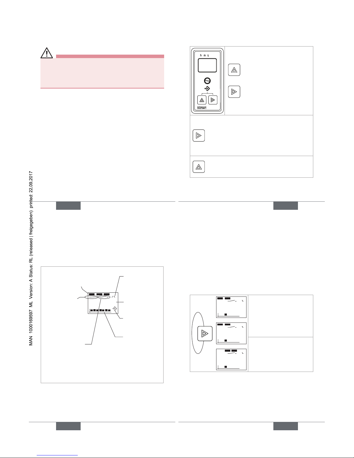
9.3.1. Adjustment keys of the 1077-2
+
To access the Settings level.
• From the Read level to go to the next time.
• From the Settings level to go to the next
function.
• To validate the setting of each function.
• At the end of the adjustment, to transfer the
new settings to the timer.
At the Settings level:
• To change the flashing numerical value.
• To go to the next choice of a function.
Fig. 12: Adjustment of the 1077-2
English
33
34
9.3.2. Display elements of the 1077-2
hms
199:99
Time units for the displayed time:
hours, minutes and/or seconds
- At the Read level:
Shows that the output is
closed
- At the Settings level:
Shows that the ON/OFF
contact is normally open
Setting for the reset
input
Shows a time. If "--:--"
is displayed the set
cycle is completed.
Shows that the device
is beeing adjusted
Shows the operating
mode
- At the Read level:
Shows that the output
is open
- At the Settings level:
Shows that the ON/OFF
contact is normally closed
Fig. 13: Display of the 1077-2
9.3.3. Operating levels
The configuration module has two operating levels: The
Read level and the Settings level.
English
35
• The Read level allows for reading the different times that
have been set and for following their count down.
• The Settings level allows for setting the operating mode,
the reset type and the times (units and values).
9.3.4. Navigating within the Read level
99:00
99:01
10:10
When the device is energized
or when the Settings level
is left, the display shows
the first running time (which
depends on the set operating
mode).The count-down of
that time starts.
The next screens show the
other set times.The number
of times depends on the set
operating mode.
Fig. 14: Navigation at the Read level
English
35
Page 10
36
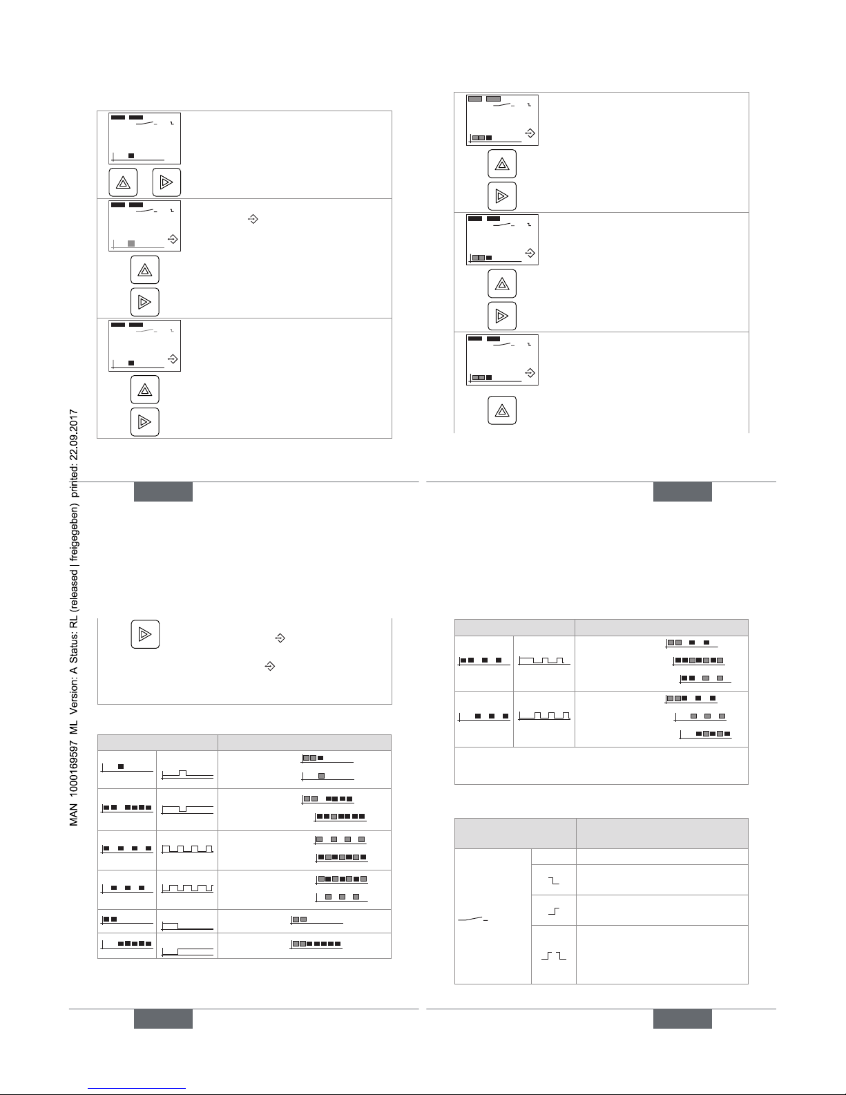
9.3.5. Accessing the Settings level
99:00
Read level
+
To access the Settings level.
99:01
a) Symbol is dispalyed and the
operating mode flashes.
→ Change the operating mode. See
Fig. 16.
→ Validate the displayed choice and
go to the next function.
99:01
b) The reset type flashes.
→ Change the reset type. See Fig.
17.
→ Validate the displayed choice and
go to the next function.
English
37
99:01
c) The time units and the first time to
be set flash.
→ Choose the time units for the first
time to be set. See Fig. 18.
→ Validate the displayed choice and
go to the next function.
99:01
d) The part of the time, that is associated to the greatest time unit, flashes.
→ Set the time associated to the
greatest time unit. See Fig. 18.
→ Validate the set value and go to the
next function.
99:01
d) The part of the time, that is associated to the smallest time unit, flashes.
→ Set the time associated to the
smallest time unit. See Fig. 18.
English
37
38
→ Validate the set value and end the
adjustment ( goes out and the
settings are saved) or go to the
next time ( is still displayed).
→ To set each additional time, repeat
steps c), d) and e).
Fig. 15: Adjustment of the 1078-2
Function Values to be set
T
on
T
off
• the delay T
off
( )
• the pulse T
on
( )
T
off
T
on
• the pulse Ton ( )
• the duration T
off
( )
T
on
T
off
• the duration T
on
( )
• the duration T
off
( )
T
on
T
off
• the duration T
off
( )
• the duration T
on
( )
T
on
T
off
the pulse Ton ( )
T
on
T
off
the delay T
off
( )
English
39
Function Values to be set
Ton1
T
off
Ton2
T
off
• the pulse Ton1 ( )
• the duration T
off
( )
• the duration T
on
2 ( ).
T
on
T
off1Toff
2
• the delay T
off
1 ( )
• the duration T
on
( )
• the duration T
off
2 ( ).
T
on
= ON duration of the valve
T
off
= OFF duration of the valve
Fig. 16: Operating modes
Symbols chosen at the
Settings level
The reset occurs...
No reset.
when the ON/OFF contact is
opened.
when the ON/OFF contact is
closed.
when the ON/OFF contact is
closed but the parametered
cycle only begins when the ON/
OFF contact is opened.
English
39
Page 11
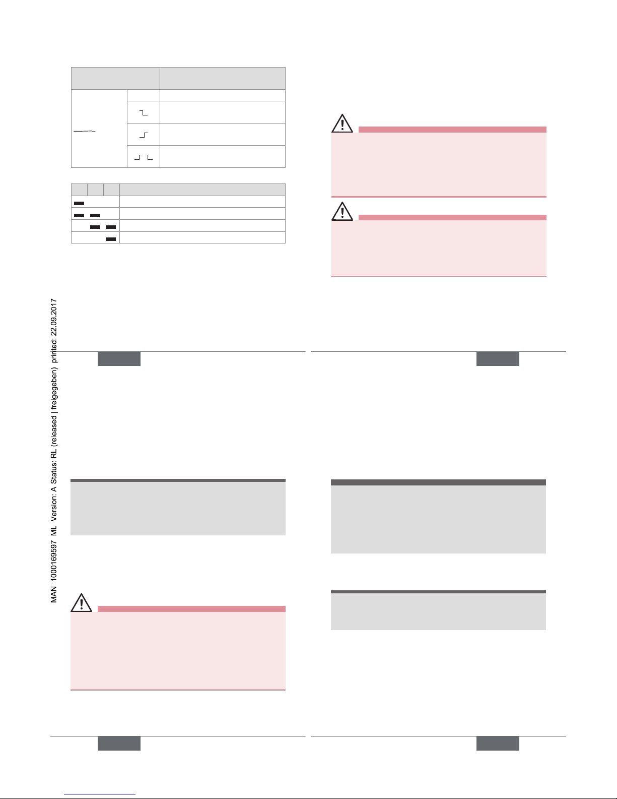
40
Symbols chosen at the
Settings level
The reset occurs...
No reset.
when the ON/OFF contact is
closed.
when the ON/OFF contact is
opened.
at each change of state of the
ON/OFF contact.
Fig. 17: Possible resets
h m s Setting range for the time
00:00h to 9999h
00:00h to 99h:59min.
00:00min. to 199min.:59s
00:00s to 199s:99
Fig. 18: Time units and associated setting ranges
English
41
10. MAINTENANCE AND
TROUBLESHOOTING
10.1. Safety information
danger
Risk of injury due to electrical voltage.
• Shut down the electrical power source of all the conductors and isolate it before carrying out work on the
system.
• Observe all applicable accident protection and safety
guidelines for electrical equipment.
Warning
Risk of injury due to non-conforming maintenance.
• Maintenance must only be carried out by qualified and
skilled staff with the appropriate tools.
• Guarantee a defined or controlled restarting of the
process subsequent to any intervention on the device.
English
41
42
10.2. Maintenance and cleaning
note
The device may be damaged by the cleaning
product.
• Clean the device with a cloth slightly dampened with
water or a cleaning product compatible with the materials from which it is made.
Please feel free to contact your Bürkert supplier for any
additional information.
11. SPARE PARTS AND
ACCESSORIES
caution
Risk of injury and/or damage by the use of incorrect
parts.
Incorrect accessories and unsuitable spare parts may
cause injuries and damage the device and the surrounding area.
• Use only original accessories and original spare parts
from Bürkert.
English
43
12. PACKAGING, TRANSPORT
note
Damage due to transport
Transport may damage an insufficiently protected device.
• Transport the device in shock-resistant packaging and
away from humidity and dirt.
• Avoid the effects of heat and cold, which could cause
the storage temperature range to be exceeded.
13. STORAGE
note
Poor storage can damage the device.
• Store the device in a dry place away from dust.
• Ambient storage temperature: -10 to +60 °C.
English
43
Page 12

44
14. DISPOSAL OF THE DEVICE
→ Dispose of the device and its packaging in an environ-
mentally-friendly way.
note
Damage to the environment caused by products
contaminated by fluids.
• Keep to the existing provisions on the subject of waste
disposal and environmental protection.
Note
Comply with the national and/or local regulations
which concern the area of waste disposal.
English
Page 13
www.burkert.com
We reserve the right to make
technical changes without notice.
Technische Änderungen
vorbehalten.
Sous réserve de modifications
techniques.
© Bürkert SAS, 2011-2014
Operating Instructions
1408/01_EU-ml_00563282_Original_FR
Types 1078-1 / 1078-2
Zeitsteuerung ohne oder mit Bedieneinheit Typ 1077-2
Bedienungsanleitung
deutsch
2
1. DIE BEDIENUNGSANLEITUNG .........................................3
2. BESTIMMUNGSGEMÄSSE VERWENDUNG................6
3. GRUNDLEGENDE SICHERHEITSHINWEISE ..............8
4. ALLGEMEINE HINWEISE .................................................... 10
5. ANWENDUNGSBEREICH ................................................... 11
6. TECHNISCHE DATEN ..........................................................15
7. INSTALLATION UND VERKABELUNG ......................... 21
8. INBETRIEBNAHME ................................................................ 24
9. BEDIENUNG ............................................................................. 26
10. WARTUNG, FEHLERBEHEBUNG ...................................42
11. ERSATZTEILE, ZUBEHÖR .................................................43
12. VERPACKUNG, TRANSPORT ........................................... 44
13. LAGERUNG ................................................................................44
14. ENTSORGUNG ........................................................................45
deutsch
3
1. DIE BEDIENUNGSANLEITUNG
Die Bedienungsanleitung beschreibt den gesamten Lebenszyklus des Gerätes. Bewahren Sie diese Anleitung so auf,
dass sie für jeden Benutzer zugänglich ist und jedem neuen
Eigentümer des Gerätes wieder zur Verfügung steht.
Die Bedienungsanleitung enthält wichtige Informationen zur Sicherheit!
Das Nichtbeachten dieser Hinweise kann zu gefährlichen
Situationen führen.
• Die Bedienungsanleitung muss gelesen und verstanden werden.
1.1. Darstellungsmittel
GEFAHR!
Warnt vor einer unmittelbaren Gefahr!
• Bei Nichteinhaltung sind Tod oder schwere Verletzungen die Folge.
WARNUNG!
Warnt vor einer möglicherweise gefährlichen
Situation!
• Bei Nichteinhaltung drohen schwere Verletzungen
oder auch der Tod.
deutsch
Page 14

4
VORSICHT!
Warnt vor einer möglichen Gefährdung!
• Nichtbeachtung kann mittelschwere oder leichte Verletzungen zur Folge haben.
HINWEIS!
Warnt vor Sachschäden!
• Bei Nichtbeachtung kann das Gerät oder die Anlage
beschädigt werden.
bezeichnet wichtige Zusatzinformationen, Tipps
und Empfehlungen, die für Ihre Sicherheit und die
einwandfreie Funktion des Gerätes wichtig sind.
bezeichnet wichtige Zusatzinformationen, Tipps
und Empfehlungen.
verweist auf Informationen in dieser Bedienungsanleitung oder in anderen Dokumentationen.
→ markiert einen Arbeitsschritt, den Sie ausführen
müssen.
deutsch
5
1.2. Begriffsdefinition "Gerät"
Der in dieser Anleitung verwendete Begriff "Gerät“ steht
immer für die Zeitsteuerung Typ 1078-1 oder 1078-2 (mit
oder ohne Bedieneinheit Typ 1077-2).
deutsch
6
2. BESTIMMUNGSGEMÄSSE
VERWENDUNG
Bei nicht bestimmungsgemäßem Einsatz der Zeitsteuerung können Gefahren für Personen, Anlagen in
der Umgebung und die Umwelt entstehen.
• Die Zeitsteuerung, ohne oder mit Bedieneinheit, dient
zur Steuerung des On/Off-Zyklus eines Magnetventils
mit kompatibler Versorgungsspannung.
• Installation, Inbetriebnahme, Bedienung und Wartung
des Geräts müssen nur durch geschultes Personal mit
elektrischer Berechtigung für die mit 110/230 V AC
versorgten Geräte durchgeführt werden.
• Schützen Sie das Gerät vor elektromagnetischen Störungen, U.V.-Bestrahlung und bei Außenanwendung
vor Witterungseinflüssen.
• Für den Einsatz sind die in den Vertragsdokumenten
und der Bedienungsanleitung spezifizierten zulässigen Daten, Betriebs- und Einsatzbedingungen zu
beachten.
• Voraussetzungen für den sicheren und einwandfreien
Betrieb sind sachgemäßer Transport, sachgemäße
Lagerung und Installation sowie sorgfältige Bedienung
und Instandhaltung.
• Setzen Sie das Gerät nur bestimmungsgemäß ein.
deutsch
7
2.1. Beschränkungen
Beachten Sie bei der Ausfuhr des Gerätes gegebenenfalls
bestehende Beschränkungen.
2.2. Vorhersehbarer Fehlgebrauch
• Dieses Gerät nicht in explosionsgefährdeten Bereichen
einsetzen.
• Belasten Sie das Gehäuse nicht mechanisch (z. B. durch
Ablage von Gegenständen oder als Trittstufe).
• Nehmen Sie keine äußerlichen Veränderungen an den
Gerätegehäusen vor. Lackieren Sie keinen Teil des Geräts.
deutsch
Page 15
8
3. GRUNDLEGENDE
SICHERHEITSHINWEISE
Diese Sicherheitshinweise berücksichtigen keine:
• Zufälligkeiten und Ereignisse, die bei Montage, Betrieb und
Wartung der Geräte auftreten können.
• Ortsbezogene Sicherheitsbestimmungen, für deren Einhaltung, auch in Bezug auf das Installations- und Wartungspersonal, der Betreiber verantwortlich ist.
Gefahr durch elektrische Spannung!
• Schalten Sie vor Beginn der Arbeiten in jedem Fall alle
existierenden am Gerät angeschlossenen SpannungsVersorgungen ab, und sichern Sie diese vor unbeabsichtigtem Wiedereinschalten!
Allgemeine Gefahrensituationen.
Zum Schutz vor Verletzungen ist zu beachten,
• dass die Anlage nicht unbeabsichtigt betätigt werden
kann.
• Installations- und Instandhaltungsarbeiten dürfen nur
von autorisiertem Fachpersonal mit geeignetem Werkzeug durchgeführt werden.
deutsch
9
Allgemeine Gefahrensituationen.
Zum Schutz vor Verletzungen ist zu beachten,
• Nach einer Unterbrechung der elektrischen Versorgung ist ein definierter oder kontrollierter Wiederanlauf
des Prozesses zu gewährleisten.
• Betreiben Sie das Gerät nur in einwandfreiem Zustand
und unter Beachtung der Bedienungsanleitung.
• Bei der Einsatzplanung und dem Betrieb des Gerätes
die allgemeinen Regeln der Technik einhalten.
HINWEIS!
Elektrostatisch gefährdete Bauelemente / Baugruppen!
• Das Gerät enthält elektronische Bauelemente, die
gegen elektrostatische Entladung (ESD) empfindlich
reagieren. Berührung mit elektrostatisch aufgeladenen Personen oder Gegenständen gefährdet diese
Bauelemente. Im schlimmsten Fall werden sie sofort
zerstört oder fallen nach der Inbetriebnahme aus.
• Beachten Sie die Anforderungen nach EN 61340-5-1, um
die Möglichkeit eines Schadens durch schlagartige elektrostatische Entladung zu minimieren bzw. zu vermeiden!
• Achten Sie ebenso darauf, dass Sie elektronische
Bauelemente nicht bei anliegender Versorgungsspannung berühren!
deutsch
10
4. ALLGEMEINE HINWEISE
4.1. Herstelleradresse und
internationale Kontaktadressen
Sie können mit dem Hersteller des Gerätes unter folgender
Adresse Kontakt aufnehmen:
Bürkert SAS
Rue du Giessen
BP 21
67220 TRIEMBACH-AU-VAL
Die Kontaktadressen finden Sie auf den letzten Seiten
dieser Bedienungsanleitung.
Außerdem im Internet unter:
www.burkert.com
4.2. Gewährleistung
Voraussetzung für die Gewährleistung ist der bestimmungsgemäße Gebrauch des Gerätes unter Beachtung der im
vorliegenden Handbuch spezifizierten Einsatzbedingungen.
4.3. Informationen im Internet
Bedienungsanleitungen und Datenblätter zum Typ 1078 oder
1077 finden Sie im Internet unter:
www.buerkert.de
deutsch
11
5. ANWENDUNGSBEREICH
Die Zeitsteuerung 1078-1 oder 1078-2 wird mittels einer
EN 175301-803-Steckdose, Form A, an ein Magnetventil
angeschlossen.
Die Zeitsteuerung dient zur Steuerung des On/Off-Zyklus
des Magnetventils.
5.1. Allgemeine Beschreibung
5.1.1. Aufbau
Die Zeitsteuerung 1078-1 oder 1078-2 ist ein Klasse II
Schaltgerät und ein Typ 1 Funktionsgerät (siehe Norm
EN 60730-1).
Die Zeitsteuerung 1078-1 oder 1078-2 ist eine Elektronikeinheit, die in einem Gehäuse mit durchsichtigem Deckel, eine
Kabelverschraubung und eine EN 175301-803-Steckdose,
Form A mit Dichtung, eingebaut ist. Die Zeitsteuerung wird
auf das Magnetventil mittels einer Schraube festgehalten.
• Die Zeitsteuerung 1078-1 wird an die Spannungs-
versorgung über die Kabelverschraubung und eine
dreipolige Klemmleiste innerhalb des Gehäuses
angeschlossen.
• Die Zeitsteuerung 1078-2 wird an die Spannungs-
versorgung über die Kabelverschraubung und eine
fünfpolige Klemmleiste innerhalb des Gehäuses
deutsch
Page 16

12
angeschlossen.
Die Zeitsteuerung versorgt das Magnetventil mit Strom.
Die Zeitsteuerung 1078-2 kann mittels der Bedieneinheit
1077-2, die Anstelle des Deckels auf den 1078-2 eingesteckt
wird, parametriert werden.
5.2. Verfügbare Ausführungen
Gerät Betriebsspannung
BestellNummer
Zeitsteuerung
1078-1
12-24 V DC 060647
24-48 V AC, 50-60 Hz,
24-48 V DC
060621
110-230 V AC,
50-60 Hz
060620
Zeitsteuerung
1078-2
12-24 V DC 060648
24-48 V AC, 50-60 Hz,
24-48 V DC
060629
Bedieneinheit 1077-2 für Zeitsteuerung
1078-2
060638
deutsch
13
5.3. Beschreibung der
Typenschilder
1078-1
Supply: 110-230V/50-60Hz 0,5A
Output: 110-230V/50-60Hz 0,5A
S/N 1000
00060620 W43ML
Made in France
1
2
3
6 5 47
1. Typ des Geräts
2. Daten der Betriebsspannung
3. Daten der an das Magnetventil versorgte Spannung
4. Herstellungscode
5. Konformitäts-Logo
6. Bestellnummer
7. Serien-Nummer
Bild 1: Typenschild Typ 1078
deutsch
14
1077-000-00-002-000-000
00060638 W45LP
Made in France
1 2
4 3
1. Typ des Geräts
2. Konformitäts-Logo
3. Herstellungscode
4. Bestellnummer
Bild 2: Typenschild Typ 1077
deutsch
15
6. TECHNISCHE DATEN
6.1. Betriebsbedingungen
Umgebungstemperatur
• 1078
• 1077
(im Betrieb)
• -10 °C...60 °C
• 0 °C...60 °C
Luftfeuchtigkeit < 85%, nicht kondensiert
Höhe über
Meeresspiegel
max. 2000 m
Verschmutzungsgrad 2
Schutzart IP65, wenn auf ein Magnetventil
mit einem Drehmoment
zwischen 0,5 und 0,8 Nm
angeschraubt, verkabelt
und Kabelverschraubung
festgeschraubt
deutsch
Page 17

16
6.2. Allgemeine technische Daten
6.2.1. Mechanische Daten
Teil Werkstoff
Gehäuse
• 1078
• 1077-2
• PA6 oder Polyarylamid
• Polyamid
Deckel PSU
EN 175301-803-Steckdose PA6
PG9-Kabelverschraubung PA6 oder Polyarylamid
M3x45- oder M3x55-Schraube 1, aus Edelstahl AL2
Dichtung der Steckdose NBR
deutsch
17
32,5
90
M3x45
42,5
36
21
Bild 3: Abmessungen [mm] des 1078
deutsch
18
53,5
21
M3x55
Bild 4: Abmessungen [mm] des 1078-2 mit 1077-2
6.2.2. Allgemeine technische Daten
Zeitbereich (1078-1)
(mechanische
Einstellung mittels den 6
Auswahlschaltern N° 1, 2,
3, 6, 7 und 8)
• 0,5 bis 10 s
(Grundeinstellung)
• 1,5 bis 30 s
• 5 bis 100 s
• 0,5 bis 10 min.
• 1,5 bis 30 min.
• 5 bis 100 min.
• 12 bis 240 min.
• 0,5 bis 10 h
deutsch
19
Zeitbereich (
1078-2)
(digitale Einstellung mittels
Bedieneinheit 1077-2)
0,2 s bis 9999 h,
kontinuierlich
Toleranz (1078-2) 1 %
Auflösung (1078-2)
• Bereich bis 199 s
• Bereich bis 199 min.
• Bereich bis 99 h
• Bereich bis 9999 h
• 10 ms
• 1 s
• 1 min.
• 1 h
6.2.3. Elektrische Daten
Tabelle 1: Elektrische Daten der 1078
Betriebsspannung
• 1078-1
• 1078-2
Toleranz 10 %
• 12-24 V DC, max. 2 A
oder 24-48 V AC/DC, max.
1,5 A oder 110/230 V AC,
max. 0,5 A
• 12-24 V DC, max. 2 A
oder 24-48 V AC/DC,
max. 1,5 A
Schutz gegen Verpolung Nein, bei Ausführungen mit
direkter Betriebsspannung
deutsch
Page 18

20
An das Magnetventil
versorgte Spannung
• Ausführung 12-24 V DC
• Ausführung
24-48 V AC/DC
• Ausführung
110/230 V AC
• 12-24 V DC, max. 2 A
• 24-48 V AC/DC, max.
1,5 A
• 110/230 V AC, max.
0,5 A
Luft- /Kriechstrecken Nach VDE 0100
Elektrischer Anschluss
• Durchmesser des
Kabels
• Querschnitt der Ader
über PG9-Kabelverschraubung
• 6 bis 7 mm
• max. 1,5 mm
2
Tabelle 2: Elektrische Daten des 1077-2
Betriebsspannung über den 1078-2 versorgt
Verbrauch 5 mW
deutsch
21
7. INSTALLATION UND
VERKABELUNG
7.1. Sicherheitshinweise
GEFAHR!
Verletzungsgefahr durch Stromschlag!
• Schalten Sie vor Beginn der Arbeiten in jedem Fall alle
existierenden am Gerät angeschlossenen SpannungsVersorgungen ab, und sichern Sie diese vor unbeabsichtigtem Wiedereinschalten!
• Den Deckel nicht öffnen, wenn das Gerät unter Spannung steht.
• Beachten Sie die Unfallverhütungs- und Sicherheitsbestimmungen für elektrische Geräte!
WARNUNG!
Verletzungsgefahr bei unsachgemäßer Installation!
• Elektrische Installation darf nur durch autorisiertes
Fachpersonal und mit geeignetem Werkzeug durchgeführt werden!
• Verwenden Sie unbedingt geeignete Sicherheitsvorrichtungen (ordnungsgemäß dimensionierte Sicherungen und/oder Schutzschalter).
deutsch
22
WARNUNG!
Verletzungsgefahr durch ungewolltes Einschalten
der Anlage und unkontrollierten Wiederanlauf!
• Anlage vor unbeabsichtigtem Betätigen sichern.
• Nach jedem Eingriff an dem Gerät einen kontrollierten
Wiederanlauf gewährleisten.
Die Spannungsversorgung schützen.
• Die Spannungsversorgung mit einer der zu schaltende Last geeignete Sicherung schützen, wenn
sie noch nicht entsprechend abgesichert ist.
• Ein abgeschirmtes Kabel mit einer Betriebsgrenztemperatur höher als + 80 °C verwenden.
• Eine hochwertige gefilterte und geregelte Spannungsversorgung verwenden.
→ Die Schraube des Deckels lausschrauben.
→ Den Deckel entfernen.
→ Die Überwurfmutter der Kabelverschraubung losschrauben.
→ Das Kabel durch die Überwurfmutter dann durch die
Kabelverschraubung führen und gemäß Bild 5 oder
Bild 6 verkabeln.
→ Die Überwurfmutter zurückschrauben.
deutsch
23
→ Den Deckel aufsetzen, dabei die Dichtung richtig
einsetzen.
→ Die Schraube mit einem Drehmoment zwischen 0,5
und 0,8 Nm festziehen.
Anschluss der Betriebsspannung
Rote LED:
während t
on
ein
und während
t
off
aus
Rote LED: ein
bei eingeschaltetem Gerät
(+) (-)
(+): V+
(-): 0V
:
Schutzerde
Bild 5: Klemmenbelegung des 1078-1
Anschluss der Bedieneinheit 1077-2
Rote LED: ein bei eingeschaltetem Gerät
Rote LED: während t
on
ein und während
t
off
aus
(+) (-)
Reset
(+): Versorgungsspannung
(-): Versorgungsspannung
: Schutzerde
Reset
: Binäreingang zum
externen Reset
(Ein/Aus-Kontakt)
Bild 6: Klemmenbelegung des 1078-2
deutsch
Page 19

24
8. INBETRIEBNAHME
8.1. Sicherheitshinweise
GEFAHR!
Verletzungsgefahr durch Stromschlag!
• Wenn das Gerät unter Spannung steht, muss der
Deckel geschlossen sein.
WARNUNG!
Verletzungsgefahr bei unsachgemäßer
Inbetriebnahme!
Nicht sachgemäßer Betrieb kann zu Verletzungen sowie
Schäden am Gerät und seiner Umgebung führen.
• Vor der Inbetriebnahme muss gewährleistet sein, dass
der Inhalt der Bedienungsanleitung dem Bedienungspersonal bekannt ist und vollständig verstanden wurde.
• Besonders zu beachten sind die Sicherheitshinweise
und die bestimmungsgemäße Verwendung.
• Das Gerät/die Anlage darf nur durch ausreichend
geschultes Personal in Betrieb genommen werden.
deutsch
25
HINWEIS!
Gefahr der Beschädigung des Geräts durch die
Umgebung!
• Schützen Sie das Gerät vor elektromagnetischen
Störungen, vor Ultraviolettbestrahlung und bei einer
Außenanwendung vor den Wetterbedingungen.
deutsch
26
9. BEDIENUNG
9.1. Sicherheitshinweise
GEFAHR!
Verletzungsgefahr durch Stromschlag!
• Beachten Sie die Unfallverhütungs- und Sicherheitsbestimmungen für elektrische Geräte!
• Bei einer mit 110-230 V AC gespeisten Version
schalten Sie vor Beginn der Arbeiten in jedem Fall alle
existierenden am Gerät angeschlossenen SpannungsVersorgungen ab, und sichern Sie diese vor unbeabsichtigtem Wiedereinschalten!
WARNUNG!
Verletzungsgefahr bei unsachgemäßer Bedienung!
Nicht sachgemäße Bedienung kann zu Verletzungen,
sowie Schäden am Gerät und seiner Umgebung führen.
• Das Bedienungspersonal muss den Inhalt der Bedienungsanleitung kennen und verstanden haben.
• Besonders zu beachten sind die Sicherheitshinweise
und die bestimmungsgemäße Verwendung.
• Das Gerät/die Anlage darf nur durch ausreichend
geschultes Personal bedient werden.
deutsch
27
9.2. Bedienung des 1078-1
GEFAHR!
Verletzungsgefahr durch Stromschlag bei einer mit
110-230 V AC gespeisten Version!
• Zur Einstellung der Potentiometer einen nicht leitenden
Schraubendreher verwenden.
HINWEIS!
Schaden an der Elektronikplatine!
• Zur Einstellung der Potentiometer einen nicht leitenden
Schraubendreher verwenden.
Die eingestellte Funktion wird gestartet sobald das
Gerät unter Spannung gesetzt wird.
• Die Funktion einstellen, bevor das mit einem Magnetventil verbundene Gerät unter Spannung gesetzt wird.
deutsch
Page 20

28
Zur Einstellung des 1078-1:
→ Die Funktion einstellen.
Schalter 4 und 5: Auswahl der
Funktion des Magnetventils
Schalter 1, 2 und 3: Einstellung
des Zeitbereichs t
on
.
Schalter 6, 7 und 8: Einstellung
des Zeitbereichs t
off
.
Potentiometer t
off
Potentiometer t
on
1ON2345678
13
13
Bild 7: Elemente zur Parametrierung des 1078-1
Die Zeitsteuerung 1078-1 dient zur Steuerung von Ein(t
on
) und Aus- (t
off
) -Schaltzeiten des Magnetventils.
Vier Funktionen können mittels der Schalter 4 und 5 eingestellt werden. Siehe Bild 7 und Bild 8.
Schalter 4
und 5
Funktion des Magnetventils
4ON5
Ein-(ton) / Aus (t
off
) -Zyklus des Magnetventils: Einen Wert für ton und einen Wert
für t
off
einstellen
T
on
T
off
4ON5
Aus- (t
off
) / Ein- (ton) ) -Zyklus des Magnetventils: Einen Wert für ton und einen Wert
für t
off
einstellen
T
on
T
off
deutsch
29
Schalter 4
und 5
Funktion des Magnetventils
4ON5
Einschaltimpuls des Magnetventils: Nur
einen Wert für ton einstellen
T
on
T
off
4ON5
Einschaltverzögerung des Magnetventils:
Nur einen Wert für die Verzögerung t
off
einstellen
T
on
T
off
Bild 8: Funktionen des 1078-1
→ Den Zeitbereich für t
on
mittels der Schalter 1, 2 und 3
und/oder t
off
mittels der Schalter 6, 7 und 8 einstellen.
Siehe Bild 7 und Bild 9.
Schalter 1, 2, 3 (ton) und 6, 7, 8 (t
off
)
Zeitbereich
1
ON
23
678
0,5-10 Sekunden
1
ON
23
678
1,5-30 Sekunden
1
ON
23
678
5-100 Sekunden
1
ON
23
678
0,5-10 Minuten
deutsch
30
Schalter 1, 2, 3 (ton) und 6, 7, 8 (t
off
)
Zeitbereich
1
ON
23
678
1,5-30 Minuten
1
ON
23
678
5-100 Minuten
1
ON
23
678
12-240 Minuten
1
ON
23
678
0,5-10 Stunden
Bild 9: Zeitbereiche für ton und t
off
→ Einschaltzeit t
on
über Potentiometer ton und/oder Aus-
schaltzeit t
off
über Potentiometer t
off
mittels eines geeig-
neten Schraubendreher einstellen. Siehe Bild 7 und
Bild 10.
deutsch
31
Stelle 1 des Potentiometers = Mindestwert des
eingestellten Zeitbereichs
(Grundeinstellung)
Stelle 3 des Potentiometers =
Bereichsende des eingestellten
Zeitbereichs
Mindestwert des Zeitbereichs + 10 % des
Zeitbereichs
Zeiger
Mindestwert des Zeitbereichs +
40 % des Zeitbereichs
Mindestwert des Zeitbereichs +
50 % des Zeitbereichs
Mindestwert des
Zeitbereichs +
80 % des Zeitbe-
reichs
13
Bild 10: Verwendung der Potentiometer des 1078-1
deutsch
Page 21

32
Zum Beispiel:
Bei Einstellung des 5-100 Sekunden-Zeitbereichs für t
on
bzw. 1,5-30 Minuten-Zeitbereichs für t
off
.
→ Bei t
on
= 50 Sekunden = Mindestwert des Bereichs
(5 s) + 45 s (45/95*100 = 47 % des Bereichs) den
Zeiger des Potentiometers ton wie folgt einstellen:
ton = Mindestwert des Zeitbereichs + 47 % des Zeitbereichs
13
→ Bei t
off
= 20 Minuten = Mindestwert des Bereichs
(1,5 min.) + 18,5 min. (18,5/28,5*100 = 65 % des
Bereichs) den Zeiger des Potentiometers t
off
wie folgt
einstellen:
13
t
off
= Mindestwert des Zeitbereichs +
65 % des Zeitbereichs
Bild 11: Einstellungsbeispiel der Potentiometer ton und t
off
des 1078-1
deutsch
33
9.3. Bedienung des 1078-2
GEFAHR!
Verletzungsgefahr durch Stromschlag!
• Bevor die Bedieneinheit 1077-2 auf die Zeitsteuerung
1078-2 eingesetzt wird, alle existierende am Gerät
angeschlossenen Spannungs-Versorgungen abschalten, und diese vor unbeabsichtigtem Wiedereinschalten sichern, damit die Einstellungen des 1078-2 nicht
geändert werden!
Zur Einstellung der Parameter des Geräts 1078-2 die
Bedieneinheit 1077-2 auf die Zeitsteuerung 1078-2
einsetzen.
→ Sicherstellen, dass die 2 roten Lichtanzeigen aus sind.
→ Die Schraube des 1078-2 lösen.
→ Den Deckel abnehmen.
→ Die Bedieneinheit 1077-2 inkl. Dichtung auf die Zeit-
steuerung 1078-2 in jener Richtung einsetzen. Siehe
Bild 6, Seite 23.
→ Die Schraube, die mit der Bedieneinheit 1077-2 mitge-
liefert ist, einsetzen.
→ Die Schraube mit einem Drehmoment zwischen 0,5
und 0,8 Nm festziehen.
deutsch
34
9.3.1. Bedienungstasten des 1077-2
+
Zugriff auf die
Einstellungs-Ebene.
• Auf der Lese-Ebene: Zur nächsten Zeit
ablesen.
• Auf der Einstellungs-Ebene: Zur nächsten
Funktion zugreifen.
• Die Einstellung jeder Funktion bestätigen.
• Am Ende des Einstellungszyklus alle Parameter
in die Zeitsteuerung übertragen.
Auf der Einstellungs-Ebene:
• Die blinkende Ziffer ändern.
• Zugriff auf die nächste Auswahl einer Funktion.
Bild 12: Bedienungstasten des 1077-2
deutsch
35
9.3.2. Anzeige des 1077-2
hms
199:99
Zeiteinheiten für die angezeigte
Zeit: Stunden, Minuten und/oder
Sekunden
- Auf der Lese-Ebene:
Zeigt an, dass der Aus-
gang eingeschaltet ist
- Auf der Einstellungs-
Ebene: Zeigt an, dass der
Resetkontakt stromlos
geöffnet ist
Parametrierung de
Reset-Eingangs
Zeigt eine Zeit an. Bei
Anzeige von "--:--" ist
der eingestellte Zeitzyklus beendet.
Zeigt an, dass das
Gerät eingestellt wird
Zeigt die Funktion an
- Auf der Lese-Ebene:
Zeigt an, dass der Aus-
gang ausgeschaltet ist
- Auf der Einstellungs-
Ebene: Zeigt an, dass der
Resetkontakt stromlos
geschlossen ist
Bild 13: Anzeige des 1077-2
deutsch
Page 22

36
9.3.3. Betriebsebenen
Die Bedieneinheit verfügt über zwei Betriebsebenen: Die
Lese-Ebene und die Einstellungs-Ebene.
• Auf der Lese-Ebene werden die eingestellten Zeiten und
die laufende Restzeit abgelesen.
• Auf der Einstellungs-Ebene werden die Funktion, den
Reset-Typ und die Zeiten (Einheit und Werte) eingestellt.
9.3.4. Navigation auf der Lese-Ebene
99:00
99:01
10:10
Beim Einschalten des
Gerätes oder bei Verlassen
der Einstellungs-Ebene wird
die ablaufende Zeit angezeigt
(hängt von der eingestellten
Funktion ab). Diese Zeit läuft
ab.
Die nächsten Bildschirme
zeigen die weiteren
eingestellten Zeiten an.
Ihre Anzahl hängt von der
eingestellten Funktion ab.
Bild 14: Navigation auf der Lese-Ebene
deutsch
37
9.3.5. Zugriff auf die
Einstellungs-Ebene
99:00
Lese-Ebene
+
Zum Zugriff auf die Einstellungs-Ebene.
99:01
a) Symbol wird angezeigt und die
Funktion blinkt.
→ Funktion ändern. Siehe Bild 16.
→ Angezeigte Auswahl bestätigen und
zum nächsten Parameter zugreifen.
99:01
b) Reset-Typ blinkt.
→ Reset-Typ ändern. Siehe Bild 17.
→ Angezeigte Auswahl bestätigen und
zum nächsten Parameter zugreifen.
deutsch
38
99:01
c) Zeiteinheit und erste zu einstellende
Zeit blinken.
→ Zeiteinheit der ersten Zeit aus-
wählen. Siehe Bild 18.
→ Angezeigte Auswahl bestätigen und
zum nächsten Parameter zugreifen.
99:01
d) Teil der Zeit, der der größten Einheit
entspricht, blinkt.
→ Teil der Zeit, der der größten Einheit
entspricht, einstellen. Siehe Bild 18.
→ Eingestellter Wert bestätigen und
zum nächsten Parameter zugreifen.
99:01
e) Teil der Zeit, der der kleinsten
Einheit entspricht, blinkt.
→ Teil der Zeit, der der kleinsten Einheit
entspricht, einstellen. Siehe Bild 18.
deutsch
39
→ Eingestellter Wert bestätigen und
Parametrierung beenden ( erlischt
und die Einstellungen werden
gespeichert) oder zur nächsten
Zeit-Einstellung ( bleibt angezeigt).
→ Zur Einstellung der nächsten Zeit
die Stufen c), d) und e) wiederholen.
Bild 15: Parametrierung des 1078-2
Funktion Zu einstellende Werte
T
on
T
off
• Verzögerung T
off
( )
• Puls T
on
( )
T
off
T
on
• Puls Ton ( )
• Zeit T
off
( )
T
on
T
off
• Zeit T
on
( )
• Zeit T
off
( )
T
on
T
off
• Zeit T
off
( )
• Zeit T
on
( )
T
on
T
off
Puls Ton ( )
T
on
T
off
Verzögerung T
off
( )
deutsch
Page 23

40
Funktion Zu einstellende Werte
Ton1
T
off
Ton2
T
off
• Puls Ton1 ( )
• Zeit T
off
( )
• Zeit T
on
2 ( ).
T
on
T
off1Toff
2
• Verzögerung T
off
1 ( )
• Zeit T
on
( )
• Zeit T
off
2 ( ).
T
on
= Einschaltzeit des Ventils
T
off
= Ausschaltzeit des Ventils
Bild 16: Funktionen
Auf der EinstellungsEbene ausgewählte
Symbole
Reset erfolgt...
Reset ausgeschaltet.
beim Öffnen des Resetkontaktes.
beim Schließen des
Resetkontaktes.
beim Schließen des Reset-
kontaktes aber die eingestellte
Funktion startet erst beim Öffnen
des Resetkontaktes.
deutsch
41
Auf der EinstellungsEbene ausgewählte
Symbole
Reset erfolgt...
Reset ausgeschaltet.
beim Schließen des
Resetkontaktes.
beim Öffnen des Resetkontaktes.
bei jeder Statusänderung des
Resetkontaktes.
Bild 17: Mögliche Resetdefinitionen
h m s Zeit-Einstellungsbereich
00:00h bis 9999h
00:00h bis 99h:59min.
00:00min. bis 199min.:59s
00:00s bis 199s:99
Bild 18: Zeiteinheiten und entsprechende
Einstellungsbereiche
deutsch
42
10. WARTUNG,
FEHLERBEHEBUNG
10.1. Sicherheitshinweise
GEFAHR!
Verletzungsgefahr durch Stromschlag!
• Schalten Sie vor Beginn der Arbeiten in jedem Fall alle
existierenden am Gerät angeschlossenen SpannungsVersorgungen ab, und sichern Sie diese vor unbeabsichtigtem Wiedereinschalten!
• Beachten Sie die Unfallverhütungs- und Sicherheitsbestimmungen für elektrische Geräte!
WARNUNG!
Gefahr durch unsachgemäße Wartungsarbeiten!
• Wartungsarbeiten dürfen nur durch autorisiertes Fachpersonal und mit geeignetem Werkzeug durchgeführt
werden!
• Nach jedem Eingriff an dem Gerät einen kontrollierten
Wiederanlauf gewährleisten.
deutsch
43
10.2. Wartung und Reinigung
HINWEIS!
Das Gerät kann durch Reinigungsmittel beschädigt
werden.
• Das Gerät nur mit einem Lappen reinigen, der leicht
mit Wasser oder einem Reinigungsmittel angefeuchtet
ist, das sich mit den Werkstoffen verträgt, aus denen
das Gerät besteht.
Für weitere Auskünfte steht Ihnen Bürkert zur Verfügung.
11. ERSATZTEILE, ZUBEHÖR
VORSICHT!
Verletzungsgefahr, Sachschäden durch ungeeignete
Teile!
Falsches Zubehör und ungeeignete Ersatzteile können
Verletzungen und Schäden am Gerät und dessen
Umgebung verursachen.
• Verwenden Sie nur Originalzubehör sowie Originalersatzteile der Fa. Bürkert.
deutsch
Page 24

44
12. VERPACKUNG, TRANSPORT
HINWEIS!
Transportschäden!
Ein unzureichend geschütztes Gerät kann durch den
Transport beschädigt werden.
• Transportieren Sie das Gerät vor Nässe und Schmutz
geschützt in einer stoßfesten Verpackung.
• Das Gerät keinen Temperaturen außerhalb des zulässigen Temperaturbereichs für die Lagerung aussetzen.
13. LAGERUNG
HINWEIS!
Falsche Lagerung kann Schäden am Gerät
verursachen!
• Lagern Sie das Gerät trocken und staubfrei!
• Lagerungstemperatur: -10 bis +60 °C.
deutsch
45
14. ENTSORGUNG
→ Entsorgen Sie das Gerät und die Verpackung
umweltgerecht.
HINWEIS!
Umweltschäden durch Teile, die durch Flüssigkeiten
kontaminiert wurden!
• Geltende Entsorgungsvorschriften und Umweltbestimmungen einhalten!
Hinweis!
Beachten Sie die nationalen
Abfallbeseitigungsvorschriften.
deutsch
46
deutsch
Page 25

www.burkert.com
We reserve the right to make
technical changes without notice.
Technische Änderungen
vorbehalten.
Sous réserve de modifications
techniques.
© Bürkert SAS, 2011-2014
Operating Instructions
1408/01_EU-ml_00563282_Original_FR
Types 1078-1 / 1078-2
Temporisateur sans ou avec module de paramétrage
1077-2
Manuel d‘utilisation
Français
2
1. A PROPOS DE CE MANUEL ................................................ 3
2. UTILISATION CONFORME ...................................................5
3. CONSIGNES DE SÉCURITÉ DE BASE .......................... 7
4. INFORMATIONS GÉNÉRALES ............................................9
5. SECTEUR D‘APPLICATION ................................................ 10
6. CARACTÉRISTIQUES TECHNIQUES .......................................................................................................14
7. INSTALLATION ET CÂBLAGE ..........................................19
8. MISE EN SERVICE ................................................................. 22
9. RÉGLAGE.................................................................................... 24
10. MAINTENANCE ET DEPANNAGE ..................................40
11. PIÈCES DE RECHANGE ET ACCESSOIRES ........... 41
12. EMBALLAGE ET TRANSPORT ......................................... 42
13. STOCKAGE ................................................................................42
14. ELIMINATION DE L'APPAREIL ......................................... 43
français
3
1. A PROPOS DE CE MANUEL
Ce manuel décrit le cycle de vie complet de l‘appareil.
Conservez-le de sorte qu‘il soit accessible à tout utilisateur
et à disposition de tout nouveau propriétaire.
Ce manuel contient des informations importantes
relatives à la sécurité.
Le non-respect de ces consignes peut entraîner des
situations dangereuses.
• Ce manuel doit être lu et compris.
1.1. Symboles utilisés
DANGER
Met en garde contre un danger imminent.
• Son non-respect peut entraîner la mort ou de graves
blessures.
AVERTISSEMENT
Met en garde contre une situation éventuellement
dangereuse.
• Son non-respect peut entraîner de graves blessures,
voire la mort.
français
Page 26

4
ATTENTION
Met en garde contre un risque éventuel.
• Son non-respect peut entraîner des blessures légères
ou de gravité moyenne.
REMARQUE
Met en garde contre des dommages matériels.
• Son non-respect peut entraîner des dommages sur
l'appareil ou l'installation.
désigne des informations supplémentaires, des
conseils ou des recommandations importants.
renvoie à des informations contenues dans ce
manuel ou dans d'autres documents.
→ indique une opération à effectuer.
1.2. Définition du terme "appareil"
Le terme "appareil" utilisé dans ce manuel se rapporte
au temporisateur type 1078-1 ou 1078-2 (avec ou sans
module de paramétrage 1077-2).
français
5
2. UTILISATION CONFORME
L‘utilisation non conforme du temporisateur peut
présenter des dangers pour les personnes, les installations proches et l‘environnement.
• Le temporisateur, sans ou avec module de paramétrage, permet de contrôler le cycle d'activation /
désactivation d'une électrovanne ayant une tension
d'alimentation compatible.
• L'installation, la mise en service, le réglage et la
maintenance de cet appareil doivent être réalisés
par du personnel qualifié, titulaire notamment de
l'habilitation électrique pour les versions alimentées en
110/230 V AC.
• Protéger cet appareil contre les perturbations électromagnétiques, les rayons ultraviolets et, lorsqu'il est installé à l'extérieur, des effets des conditions climatiques.
• Utiliser cet appareil conformément aux caractéristiques et conditions de mise en service et d'utilisation
indiquées dans les documents contractuels et dans le
manuel utilisateur.
• L'utilisation en toute sécurité et sans problème de
l'appareil repose sur un transport, un stockage et une
installation corrects ainsi que sur une utilisation et une
maintenance effectuées avec soin.
• Veiller à toujours utiliser cet appareil de façon
conforme.
français
6
2.1. Restrictions
Respecter les restrictions éventuelles lorsque l‘appareil est
exporté.
2.2. Mauvaise utilisation prévisible
• Ne pas utiliser cet appareil dans une atmosphère explosible.
• Ne pas soumettre l‘appareil à des contraintes mécaniques
(par ex. en y déposant des objets ou en l‘utilisant comme
marchepied).
• N‘apporter aucune modification extérieure au corps. Ne
laquer aucune partie de l‘appareil.
français
7
3. CONSIGNES DE SÉCURITÉ DE
BASE
Ces consignes de sécurité ne tiennent pas compte :
• des imprévus pouvant survenir lors du montage, de
l‘utilisation et de l‘entretien des appareils.
• des prescriptions de sécurité locales que l‘exploitant est
tenu de faire respecter par le personnel chargé du montage.
DANGER
Danger dû à la tension électrique.
• Couper l'alimentation de tous les conducteurs et
consigner l'alimentation électrique avant d'intervenir
sur l'installation.
Situations dangereuses diverses
Pour éviter toute blessure, veiller à :
• empêcher toute mise sous tension involontaire de
l'installation.
• ce que les travaux d'installation et de maintenance
soient effectués par du personnel qualifié et habilité,
disposant des outils appropriés.
• garantir un redémarrage défini et contrôlé du process,
après une coupure de l'alimentation électrique.
français
Page 27
8
Situations dangereuses diverses
Pour éviter toute blessure, veiller à :
• n'utiliser l'appareil qu'en parfait état et en tenant
compte des indications du manuel utilisateur.
• respecter les règles générales de la technique lors de
l'implantation et de l'utilisation de l'appareil.
REMARQUE
Eléments / Composants sensibles aux décharges
électrostatiques
• Cet appareil contient des composants électroniques
sensibles aux décharges électrostatiques. Ils peuvent
être endommagés lorsqu'ils sont touchés par une personne ou un objet chargé électrostatiquement. Dans
le pire des cas, ils sont détruits instantanément ou
tombent en panne sitôt effectuée la mise en route.
• Pour réduire au minimum voire éviter tout dommage
dû à une décharge électrostatique, prenez toutes les
précautions décrites dans la norme EN 61340-5-1.
• Veiller également à ne pas toucher les composants
électriques sous tension.
français
9
4. INFORMATIONS GÉNÉRALES
4.1. Adresse du fabricant et
contacts internationaux
Le fabricant de l‘appareil peut être contacté à l‘adresse
suivante :
Bürkert SAS
Rue du Giessen
BP 21
67220 TRIEMBACH-AU-VAL
Les adresses des filiales internationales figurent sur les
dernières pages de ce manuel imprimé.
Elles sont également disponibles sur internet sous :
www.burkert.com
4.2. Conditions de garantie
La condition pour bénéficier de la garantie légale est
l‘utilisation conforme de l‘appareil dans le respect des conditions d‘utilisation spécifiées dans le présent manuel.
4.3. Informations sur internet
Retrouvez sur internet le manuel utilisateur et la fiche technique relatifs au type 1078 ou 1077 sous :
www.burkert.fr
français
10
5. SECTEUR D‘APPLICAT ION
Le temporisateur 1078-1 ou 1078-2 se connecte sur une
électrovanne grâce à une embase EN 175301-803 forme A.
Le temporisateur permet de contrôler le cycle d'activation /
désactivation de l'électrovanne.
5.1. Description générale
5.1.1. Construction
Le temporisateur 1078-1 ou 1078-2 est un dispositif de
commande de classe II et d'action de type 1 (voir la norme
EN 60730-1).
Le temporisateur 1078-1 ou 1078-2 est un module électronique contenu dans un boîtier avec un couvercle transparent,
un presse-étoupe, une embase électrique EN 175301-803
femelle, de forme A, et son joint d'étanchéité. Le temporisateur
est maintenu sur l'électrovanne grâce à une vis.
• Le temporisateur 1078-1 est raccordé à l'alimentation
électrique via le presse-étoupe, par l'intermédiaire d'un
bornier à 3 vis à l'intérieur du boîtier.
• Le temporisateur 1078-2 est raccordé à l'alimentation
électrique via le presse-étoupe, par l'intermédiaire d'un
bornier à 5 vis à l'intérieur du boîtier.
Le temporisateur alimente l'électrovanne en électricité.
français
11
Le temporisateur 1078-2 peut être paramétré à l'aide du
module de configuration 1077-2, inséré sur le 1078-2 à la
place du couvercle de ce dernier.
5.2. Versions disponibles
Appareil Tension d'alimentation
Référence de
commande
Temporisateur
1078-1
12-24 V DC 060647
24-48 V AC, 50-60 Hz,
24-48 V DC
060621
110-230 V AC,
50-60 Hz
060620
Temporisateur
1078-2
12-24 V DC 060648
24-48 V AC, 50-60 Hz,
24-48 V DC
060629
Module de paramétrage 1077-2 pour
temporisateur 1078-2
060638
français
Page 28

12
5.3. Description des étiquettes
d‘identification
1078-1
Supply: 110-230V/50-60Hz 0,5A
Output: 110-230V/50-60Hz 0,5A
S/N 1000
00060620 W43ML
Made in France
1
2
3
6 5 47
1. Type de l'appareil
2. Caractéristiques de l'alimentation électrique
3. Caractéristiques de l'alimentation électrique fournie à
l'électrovanne
4. Code de construction
5. Logo de conformité
6. Référence de commande
7. Numéro de série
Fig. 1 : Etiquette d’identification du 1078
français
13
1077-000-00-002-000-000
00060638 W45LP
Made in France
1 2
4 3
1. Type de l'appareil
2. Logo de conformité
3. Code de construction
4. Référence de commande
Fig. 2 : Etiquette d’identification du 1077
français
14
6. CARACTÉRISTIQUES TECHNIQUES
6.1. Conditions d'utilisation
Température ambiante
• 1078
• 1077
(en fonctionnement)
• -10 °C...60 °C
• 0 °C...60 °C
Humidité de l'air < 85 %, non condensée
Altitude 2000 m max.
Degré de pollution 2
Indice de protection IP65, vissé sur une électrovanne
avec un couple de serrage
compris entre 0,5 et 0,8 Nm,
câblé et presse-étoupe serré
6.2. Caractéristiques techniques
générales
6.2.1. Caractéristiques mécaniques
Elément Matériau
Boîtier
• 1078
• 1077-2
• PA6 ou polyarylamide
• Polyamide
français
15
Elément Matériau
Couvercle PSU
Embase électrique femelle
EN 175301-803
PA6
Presse-étoupe PG9 PA6 ou polyarylamide
Vis M3x45 ou M3x55 1, en acier inoxydable AL2
Joint de l'embase
électrique femelle
NBR
32,5
90
M3x45
42,5
36
21
Fig. 3 : Dimensions [mm] du 1078
français
Page 29

16
53,5
21
M3x55
Fig. 4 : Dimensions [mm] du 1078-2 associé au 1077-2
6.2.2. Caractéristiques générales
Plage de temps (1078-1)
(paramétrage mécanique
à l'aide des 6 sélecteurs
N° 1, 2, 3, 6, 7 et 8)
• 0,5 à 10 s (réglage par
défaut)
• 1,5 à 30 s
• 5 à 100 s
• 0,5 à 10 min.
• 1,5 à 30 min.
• 5 à 100 min.
• 12 à 240 min.
• 0,5 à 10 h
français
17
Plage de temps (
1078-2)
(paramétrage numérique
par module 1077-2)
0,2 s à 9999 h en continu
Tolérance (1078-2) 1 %
Résolution (1078-2)
• jusqu'à 199 s
• jusqu'à 199 min.
• jusqu'à 99 h
• jusqu'à 9999 h
• 10 ms
• 1 s
• 1 min.
• 1 h
6.2.3. Caractéristiques électriques
Table 1 : Caractéristiques électriques des 1078
Alimentation électrique
• 1078-1
• 1078-2
Tolérance 10 %
• 12-24 V DC, max. 2 A
ou 24-48 V AC/DC, max
1,5 A ou 110/230 V AC,
max 0,5 A
• 12-24 V DC, max. 2 A
ou 24-48 V AC/DC, max
1,5 A
Protégé contre l'inversion
de polarité
Non, versions alimentées en
tension continue
français
18
Alimentation électrique
fournie à l'électrovanne
• version 12-24 V DC
• version 24-48 V AC/DC
• version 110/230 V AC
• 12-24 V DC, max. 2 A
• 24-48 V AC/DC, max
1,5 A
• 110/230 V AC, max 0,5 A
Distance d'isolement et
lignes de fuite
Selon VDE 0100
Raccordement électrique
• Diamètre du câble
• Section des fils
via presse-étoupe PG9
• 6 à 7 mm
• max. 1,5 mm
2
Table 2 : Caractéristiques électriques du 1077-2
Tension d'alimentation Alimenté par le 1078-2
Puissance consommée 5 mW
français
19
7. INSTALLAT ION ET CÂBLAGE
7.1. Consignes de sécurité
DANGER
Risque de blessure par décharge électrique.
• Couper l'alimentation de tous les conducteurs et
consigner l'alimentation électrique avant d'intervenir
sur l'installation.
• Ne pas dévisser le couvercle lorsque l'appareil est
sous tension.
• Respecter la réglementation en vigueur en matière de
prévention des accidents et de sécurité relative aux
appareils électriques.
AVERTISSEMENT
Risque de blessure dû à une installation non
conforme.
• L'installation électrique ne peut être effectuée que par
du personnel habilité et qualifié, disposant des outils
appropriés.
• Utiliser impérativement les dispositifs de sécurité
adaptés (fusible correctement dimensionné et/ou
coupe-circuit).
français
Page 30

20
AVERTISSEMENT
Risque de blessure dû à une mise sous tension
involontaire de l'installation et à un redémarrage
incontrôlé.
• Protéger l'installation contre toute mise sous tension
involontaire.
• Garantir un redémarrage contrôlé de l'installation,
après toute intervention sur l'appareil.
Protéger l'alimentation électrique.
• Equiper l'alimentation avec un fusible adapté à
la charge à commuter, si l'alimentation n'est pas
protégée par défaut.
• Utiliser un câble blindé avec une température
limite de service > +80 °C.
• Utiliser une alimentation électrique de qualité,
filtrée et régulée.
→ Desserrer la vis du couvercle du boîtier.
→ Retirer le couvercle.
→ Desserrer l'écrou du presse-étoupe.
→ Insérer le câble dans l'écrou puis dans le presse-
étoupe et câbler selon la Fig. 5 ou la Fig. 6.
→ Resserrer le presse-étoupe.
français
21
→ Mettre en place le couvercle, en veillant à la position
correcte du joint d'étanchéité.
→ Serrer la vis fournie avec un couple de serrage compris
entre 0,5 et 0,8 Nm.
Branchement de l'alimentation électrique
Voyant rouge :
allumé pendant
t
on
et éteint
pendant t
off
Voyant rouge :
allumé lorsque
l'appareil est
alimenté
(+) (-)
(+) : V+
(-) : 0V
: Terre
de protection
Fig. 5 : Affectation des bornes du 1078-1
Branchement du
module de configuration
1077-2
Voyant rouge : allumé
lorsque l'appareil est
alimenté
Voyant rouge : allumé pendant t
on
et éteint
pendant t
off
(+) (-)
Reset
(+) : Alimentation
électrique
(-) : Alimentation
électrique
: Terre de
protection
Reset
: Entrée
binaire (contact
sec)
Fig. 6 : Affectation des bornes du 1078-2
français
22
8. MISE EN SERVICE
8.1. Consignes de sécurité
DANGER
Risque de choc électrique
• Lorsque l'appareil est sous tension, le couvercle doit
être fermé.
AVERTISSEMENT
Risque de blessure dû à une mise en service non
conforme.
La mise en service non conforme peut entraîner des blessures et endommager l'appareil et son environnement.
• S'assurer avant la mise en service que le personnel qui
en est chargé a lu et parfaitement compris le contenu
de ce manuel.
• Respecter en particulier les consignes de sécurité et
l'utilisation conforme.
• L'appareil / l'installation ne doit être mis(e) en service
que par du personnel suffisamment formé.
français
23
REMARQUE
Risque de détérioration de l'appareil dû à
l'environnement
• Protéger l’appareil contre les perturbations électromagnétiques, les rayons ultraviolets et, lorsqu’il est installé à l’extérieur, des effets des conditions climatiques.
français
Page 31
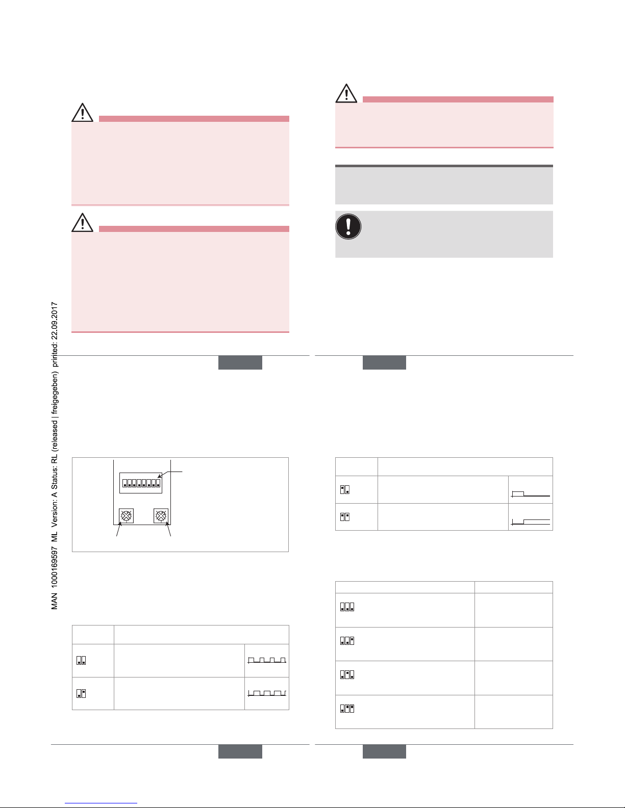
24
9. RÉGLAGE
9.1. Consignes de sécurité
DANGER
Risque de blessure par décharge électrique
• Respecter la réglementation en vigueur en matière de
prévention des accidents et de sécurité relative aux
appareils électriques.
• Pour les versions alimentées en 110-230 V AC, couper l'alimentation de tous les conducteurs et consigner
l'alimentation électrique avant d'effectuer le réglage de
l'appareil.
AVERTISSEMENT
Risque de blessure dû à un réglage non conforme.
Le réglage non conforme peut entraîner des blessures et
endommager l'appareil et son environnement.
• Les opérateurs chargés du réglage doivent avoir pris
connaissance et compris le contenu de ce manuel.
• Respecter en particulier les consignes de sécurité et
l'utilisation conforme.
• L'appareil / l'installation ne doit être réglé(e) que par
du personnel suffisamment formé.
français
25
9.2. Réglage du 1078-1
DANGER
Risque de choc électrique sur une version alimentée
en 110-230 V AC.
• Pour le réglage des potentiomètres, utiliser un tournevis non conducteur.
REMARQUE
Risque d'endommager la carte électronique
• Pour le réglage des potentiomètres, utiliser un tournevis non conducteur.
Le mode de pilotage paramétré démarre à la mise
sous tension de l'appareil.
• Régler le mode de pilotage avant de mettre sous
tension l'appareil associé à l'électrovanne.
Pour régler le 1078-1 :
→ Paramétrer le mode de pilotage.
français
26
Interrupteurs 4 et 5 : sélection du
mode de pilotage de l'électrovanne
Interrupteurs 1, 2 et 3 : réglage de
la plage t
on
.
Interrupteurs 6, 7 et 8 : réglage de
la plage t
off
.
Potentiomètre t
off
Potentiomètre t
on
1ON2345678
13
13
Fig. 7 : Éléments de paramétrage du 1078-1
Le temporisateur 1078-1 permet de contrôler le cycle
d'activation (appelé t
on
) / désactivation (appelé t
off
) d'une
électrovanne.
Quatre modes de pilotage peuvent être paramétrés à l'aide
des interrupteurs 4 et 5. Voir Fig. 7 et Fig. 8.
Interrupteurs
4 et 5
Mode de pilotage de l'électrovanne
4ON5
Cycles d'activation (ton)/désactivation (t
off
)
de la vanne : régler une valeur pour ton et
une valeur pour t
off
T
on
T
off
4ON5
Cycles de désactivation (t
off
)/activation (ton)
de la vanne : régler une valeur pour ton et
une valeur pour t
off
T
on
T
off
français
27
Interrupteurs
4 et 5
Mode de pilotage de l'électrovanne
4ON5
Activation temporisée de la vanne : régler
uniquement une valeur pour t
on
T
on
T
off
4ON5
Activation retardée de la vanne : régler
uniquement une valeur pour le retard t
off
T
on
T
off
Fig. 8 : Modes de pilotage du 1078-1
→ Paramétrer la plage de temps pour t
on
à l'aide des inter-
rupteurs 1, 2 et 3 et/ou t
off
, à l'aide des interrupteurs 6,
7 et 8. Voir Fig. 7 et Fig. 9.
Interrupteurs 1, 2, 3 (ton) et 6, 7, 8 (t
off
)
Plage de temps
1
ON
23
678
0,5-10 secondes
1
ON
23
678
1,5-30 secondes
1
ON
23
678
5-100 secondes
1
ON
23
678
0,5-10 minutes
français
Page 32

28
Interrupteurs 1, 2, 3 (ton) et 6, 7, 8 (t
off
)
Plage de temps
1
ON
23
678
1,5-30 minutes
1
ON
23
678
5-100 minutes
1
ON
23
678
12-240 minutes
1
ON
23
678
0,5-10 heures
Fig. 9 : Plages de temps pour ton et t
off
→ Paramétrer la durée d'activation t
on
à l'aide du poten-
tiomètre ton et/ou la durée de désactivation t
off
à l'aide
du potentiomètre t
off
, en utilisant un tournevis plat de
dimension appropriée. Voir Fig. 7 et Fig. 10.
français
29
Position 1 du potentiomètre =
minimum de la plage de temps
sélectionnée (position par
défaut)
Position 3 du potentiomètre =
pleine échelle de la plage de
temps sélectionnée
min. de la plage +
10 % de la plage de
temps
Curseur
min. de la plage + 40 % de la
plage de temps
min. de la plage + 50 % de la
plage de temps
min. de la plage
+ 80 % de la
plage de temps
13
Fig. 10 : Utilisation des potentiomètres du 1078-1
français
30
Par exemple :
Soit la plage de temps 5-100 secondes sélectionnée
pour t
on
et la plage 1,5-30 minutes sélectionnée pour t
off
.
→ Si t
on
= 50 secondes = min. de la plage (5 s) + 45 s
(45/95*100 = 47 % de la plage), régler le curseur du
potentiomètre t
on
comme suit :
ton = min. de la plage + 47 % de la plage de temps
13
→ Si t
off
= 20 minutes = min. de la plage (1,5 min.) +
18,5 min. (18,5/28,5*100 = 65 % de la plage), régler
le curseur du potentiomètre t
off
comme suit :
13
t
off
= min. de la plage + 65 % de la plage
de temps
Fig. 11 : Exemple de réglage des potentiomètres ton et t
off
du 1078-1
français
31
9.3. Réglage du 1078-2
DANGER
Risque de choc électrique.
• Couper l'alimentation de tous les conducteurs et consigner l'alimentation électrique pour ne pas modifier le
paramétrage du 1078-2 avant d'insérer le module de
configuration 1077-2 sur le temporisateur 1078-2.
Pour modifier le paramétrage du 1078-2, installer un
module de configuration 1077-2 sur le temporisateur
1078-2.
→ Vérifier que les 2 voyants rouges sont éteints.
→ Dévisser la vis du 1078-2.
→ Retirer le couvercle.
→ Insérer le 1077-2, avec son joint d'étanchéité, sur le
1078-2, dans l’un ou l’autre sens. Voir Fig. 6, page
21.
→ Insérer la vis fournie avec le 1077-2.
→ Serrer la vis avec un couple de vissage compris entre
0,5 et 0,8 Nm.
français
Page 33

32
9.3.1. Connaître les touches de
réglage du 1077-2
+
Accéder au niveau
paramétrage.
• Dans le niveau Lecture, aller à la temporisation
suivante.
• Dans le niveau paramétrage, aller à la fonction
suivante.
• Valider le paramétrage de chaque fonction.
• A la fin de la séquence de paramétrage, transférer les paramètres au temporisateur.
Dans le niveau paramétrage :
• Modifier la valeur numérique qui clignote.
• Aller au choix suivant pour une fonction.
Fig. 12 : Touches de réglage du 1077-2
français
33
9.3.2. Connaître l'afficheur du 1077-2
hms
199:99
Unités de temps de la tempori-
sation affichée : heures, minutes
et/ou secondes
- Au niveau Lecture :
indique que la sortie est
commutée
- Au niveau Paramétrage :
indique que le contact
sec est normalement
ouvert
Paramétrage de
l'entrée Reset
Indique une temporisation. Si "--:--" est
affiché, le cycle paramétré est terminé.
Indique que l'appareil
est en cours de
paramétrage
Indique le mode de
fonctionnement
- Au niveau Lecture :
indique que la sortie est
ouverte
- Au niveau Paramétrage :
indique que le contact
sec est normalement
fermé
Fig. 13 : Afficheur du 1077-2
9.3.3. Connaître les niveaux d'utilisation
Le module de configuration comprend 2 niveaux
d'utilisation : le niveau Lecture et le niveau Paramétrage.
français
34
• Le niveau Lecture permet de lire les différentes temporisations paramétrées et de suivre leur décompte.
• Le niveau Paramétrage permet de régler le mode de
fonctionnement, le type de réinitialisation et les durées
(unités de temps et valeurs).
9.3.4. Naviguer dans le niveau Lecture
99:00
99:01
10:10
A la mise sous tension de
l'appareil ou lorsque vous
quittez le mode Paramétrage,
le premier écran indique la
temporisation active (dépend
du mode de fonctionnement
paramétré). Le décompte de
cette temporisation démarre.
Les écrans suivants indiquent
les autres temporisations
paramétrées. Leur nombre
dépend du mode de
fonctionnement paramétré.
Fig. 14 : Navigation dans le niveau Lecture
français
35
9.3.5. Accéder au niveau Paramétrage
99:00
Niveau Lecture
+
Pour accéder au niveau Paramétrage.
99:01
a) Le symbole s'affiche et le mode
de fonctionnement clignote.
→ Modifier le mode de fonction-
nement. Voir Fig. 16.
→ Valider le choix affiché et aller à la
fonction suivante.
99:01
b) Le type de réinitialisation clignote.
→ Modifier le type de réinitialisation.
Voir Fig. 17.
→ Valider le choix affiché et aller à la
fonction suivante.
français
Page 34

36
99:01
c) Les unités de temps et la première
durée à paramétrer clignotent.
→ Choisir les unités de temps pour la
première durée. Voir Fig. 18.
→ Valider le choix affiché et aller à la
fonction suivante.
99:01
d) La part de la durée, associée à
l'unité la plus grande, clignote.
→ Régler la part de la durée associée
à l'unité la plus grande. Voir Fig. 18.
→ Valider la valeur réglée et aller à la
fonction suivante.
99:01
e) La part de la durée, associée à
l'unité la plus petite, clignote.
→ Régler la part de la durée associée
à l'unité la plus petite. Voir Fig. 18.
français
37
→ Valider la valeur réglée et terminer
le paramétrage ( s'éteint et les
réglages sont sauvegardés) ou
aller à la durée suivante ( reste
affiché).
→ Pour paramétrer chaque durée
supplémentaire, répéter les étapes
c), d) et e).
Fig. 15 : Paramétrage du 1078-2
Fonction Valeurs à paramétrer
T
on
T
off
• le délai T
off
( )
• l'impulsion T
on
( )
T
off
T
on
• l'impulsion Ton ( )
• la durée T
off
( )
T
on
T
off
• la durée T
on
( )
• la durée T
off
( )
T
on
T
off
• la durée T
off
( )
• la durée T
on
( )
T
on
T
off
l'impulsion Ton ( )
T
on
T
off
le délai T
off
( )
français
38
Fonction Valeurs à paramétrer
Ton1
T
off
Ton2
T
off
• l'impulsion Ton1 ( )
• la durée T
off
( )
• la durée T
on
2 ( ).
T
on
T
off1Toff
2
• le délai T
off
1 ( )
• la durée T
on
( )
• la durée T
off
2 ( ).
T
on
= durée d'activation de la vanne
T
off
= durée de désactivation de la vanne
Fig. 16 : Modes de fonctionnement
Symboles sélectionnés
au niveau Paramétrage
La réinitialisation intervient...
Pas de réinitialisation.
à l'ouverture du contact sec.
à la fermeture du contact sec.
à la fermeture du contact sec
mais le cycle paramétré ne
démarre qu'à l'ouverture du
contact sec.
français
39
Symboles sélectionnés
au niveau Paramétrage
La réinitialisation intervient...
Pas de réinitialisation.
à la fermeture du contact sec.
à l'ouverture du contact sec.
à chaque changement d'état du
contact sec.
Fig. 17 : Réinitialisations possibles
h m s Plage de réglage du temps
00:00h à 9999h
00:00h à 99h:59min.
00:00min. à 199min.:59s
00:00s à 199s:99centièmes
Fig. 18 : Unités de temps et plages de réglage associées
français
Page 35

40
10. MAINTENANCE ET
DEPANNAGE
10.1. Consignes de sécurité
DANGER
Risque de blessure par décharge électrique.
• Couper l'alimentation de tous les conducteurs et
consigner l'alimentation électrique avant d'intervenir
sur l'installation.
• Respecter la réglementation en vigueur en matière de
prévention des accidents et de sécurité relative aux
appareils électriques.
AVERTISSEMENT
Danger dû à une maintenance non conforme.
• Ces travaux doivent être effectués uniquement par
du personnel qualifié et habilité, disposant des outils
appropriés.
• Garantir un redémarrage contrôlé de l'installation,
après toute intervention sur l'appareil.
français
41
10.2. Entretien et nettoyage
REMARQUE
L'appareil peut être endommagé par le produit de
nettoyage.
• Nettoyer l'appareil avec un chiffon légèrement imbibé
d'eau ou d'un produit compatible avec les matériaux
qui composent l'appareil.
Votre fournisseur Bürkert reste à votre entière disposition
pour tous renseignements complémentaires.
11. PIÈCES DE RECHANGE ET
ACCESSOIRES
ATTENTION
Risque de blessure et de dommage matériel dus à
l'utilisation de fausses pièces.
Un mauvais accessoire ou une pièce de rechange inadaptée peuvent entrainer des blessures et endommager
l'appareil et son environnement.
• N'utiliser que les accessoires et pièces détachées
d'origine de la société Bürkert.
français
42
12. EMBALLAGE ET TRANSPORT
REMARQUE
Dommages dus au transport
Le transport peut endommager un appareil insuffisamment protégé.
• Transporter l'appareil dans un emballage résistant aux
chocs, à l'abri de l'humidité et des impuretés.
• Eviter les effets de la chaleur et du froid pouvant
entrainer le dépassement de la plage de température
de stockage.
13. STOCKAGE
REMARQUE
Un mauvais stockage peut endommager l'appareil.
• Stocker l'appareil dans un endroit sec et à l'abri de la
poussière.
• Température ambiante de stockage -10 à +60 °C.
français
43
14. ELIMINAT ION DE L'APPAREIL
→ Eliminer l'appareil et l'emballage dans le respect de
l'environnement.
REMARQUE
Dommages à l'environnement causés par des pièces
contaminées par des fluides.
• Respecter les prescriptions en vigueur en matière d'élimination des déchets et de protection de
l'environnement.
Remarque
Respecter les prescriptions nationales en matière
d'élimination des déchets .
français
 Loading...