

Bürkert 0911 Operating Instructions Manual
Operating Instructions
Bedienungsanleitung
Instructions de Service
Type 0911
2 stage controller
2-Punkt-Regler
2 Régulateur Ponctuel
Id. No. 788 263
788 264
788 265
788 266

We reserve the right to make technical changes without notice.
Technische Änderungen vorbehalten.
Sous resérve de modification techniques.
© 2004 - 2017 Bürkert Werke GmbH & Co. KG
Operating Instructions 1706/03_EU-ml_00804604

2-STAGE CONTROLLER
TYPE 0911
1 GENERAL INFORMATION ........................................................................................................................ 2
1.1 Symbols ......................................................................................................................................................... 2
1.2 Safety notes ................................................................................................................................................ 2
1.3 Scope of delivery ...................................................................................................................................... 3
1.4 Warranty provisions ............................................................................................................................... 3
2 SYSTEM DESCRIPTION ............................................................................................................................ 4
2.1 General description ................................................................................................................................. 4
2.2 Operation ...................................................................................................................................................... 4
2.3 Before the installation ............................................................................................................................. 7
2.4 Parameters .................................................................................................................................................. 8
2.5 Controlling the loads ............................................................................................................................. 11
3 TECHNICAL DATA ..................................................................................................................................... 12
4 ASSEMBLY, INSTALLATION AND COMMISSIONING .......................................................... 13
4.1 General information regarding the installation and operation ......................................... 13
4.2 Assembly .................................................................................................................................................... 13
english
4.3 Electrical connections .......................................................................................................................... 14
5 HOT-KEY FUNCTION ................................................................................................................................. 16
6 FACTORY SETTING .................................................................................................................................. 17
7 MAINTENANCE ............................................................................................................................................18
8 REPAIR WORK .............................................................................................................................................. 19
8.1 Faults............................................................................................................................................................. 19
8.2 Ordering table for basic unit/accessories ................................................................................ 20
0911 - 1
1 GENERAL INFORMATION
1.1 Symbols
The following symbols are used in these operating instructions:
marks a work step that must be carried out.
ATTENTION!
english
NOTE indicates important additional information,
1.2 Safety notes
Please observe the notes in these operating instructions together with the
conditions of use and permitted data that are specified in the data sheets of
the 0911 controller, so that the device will function perfectly and will have a
long service life.
• Keep to the standard engineering rules when planning and operating the
device!
• Installation and maintenance work may only be carried out by specialist
personnel using the correct tools!
• Observe the current regulations on accident prevention and the safety
regulations for electrical devices during the operation and maintenance of
the device!
• Comply with the intended usage of the device.
• Only operate the device with its housing fitted.
• Before connecting the device, check that the power supply corresponds to
the values printed on the device.
• Check that the connections are correct before switching on the device.
• Observe the maximum load of the relay contacts (see technical data).
• Ensure that all sensors are installed with sufficient separation from voltageconducting lines. This will avoid incorrect temperature readings and will
protect the device from voltage interference at the sensor inputs.
• For applications in the industrial sector with critical environments, switch an
RC element in parallel (FT1).
• Always switch off the mains supply before carrying out manipulations on
the system.
• Take suitable measures to exclude unintended operation and damage by
unauthorised operation!
indicates information which, if ignored, could lead to a risk to
your health or to the functionality of the device.
tips and recommendations.
2 - 0911
• Please observe the prescribed environmental conditions with regard to
dampness and temperature limits. Malfunctions cannot be excluded if these
conditions are not complied with.
• Call in your authorised Bürket sales centre in case of doubt or faulty
functioning.
In the case of the non-observance of these notes or of unauthorised
manipulation of the device, we will accept no liability, and the guarantee on the
device and its accessories will become void!
1.3 Scope of delivery
Immediately after receiving the delivery, ensure that the contents agree with
the scope of the delivery. This includes:
• 1 Type 0911 controller
• 1 set of operating instructions (where required, on a data carrier)
• 1 front seal
• 2 Mounting clamps
In case of discrepancy, please contact our Customer centre immediately:
Bürkert Steuer- und Regelungstechnik
or your Bürkert Sales Centre.
1.4 Warranty provisions
english
Service-Abteilung
Chr.-Bürkert-Str. 13-17
D-76453 Ingelfingen
Tel. : 07940-10111
Bürkert provideds a guarantee of one year on the correct functioning of the
controller, under the precondition that the device is employed for its intended
use and under compliance with the specified conditions for use.
If the functions of the device are not in order, the respective device will be
repaired free of charge or will be replaced.
ATTENTION!
The warranty only covers the the controller and its components, but does not cover consequential damage of any kind
that could arise from the failure or malfunctioning of the device.
0911 - 3
2 SYSTEM DESCRIPTION
2.1 General description
2-point controller, 74 x 32 mm, with predefinable control function (e.g., heating/
cooling or moisten/dehumidify)
The following models are available:
Type Configurable Input Parameter UDM
english
TU
Temperature
controller
PTC, NTC, Pt100
Thermoelements J, K, S
(Defined by display unit)
UDM = °C
UDM = °F
AU
Control device with
current / voltage
input
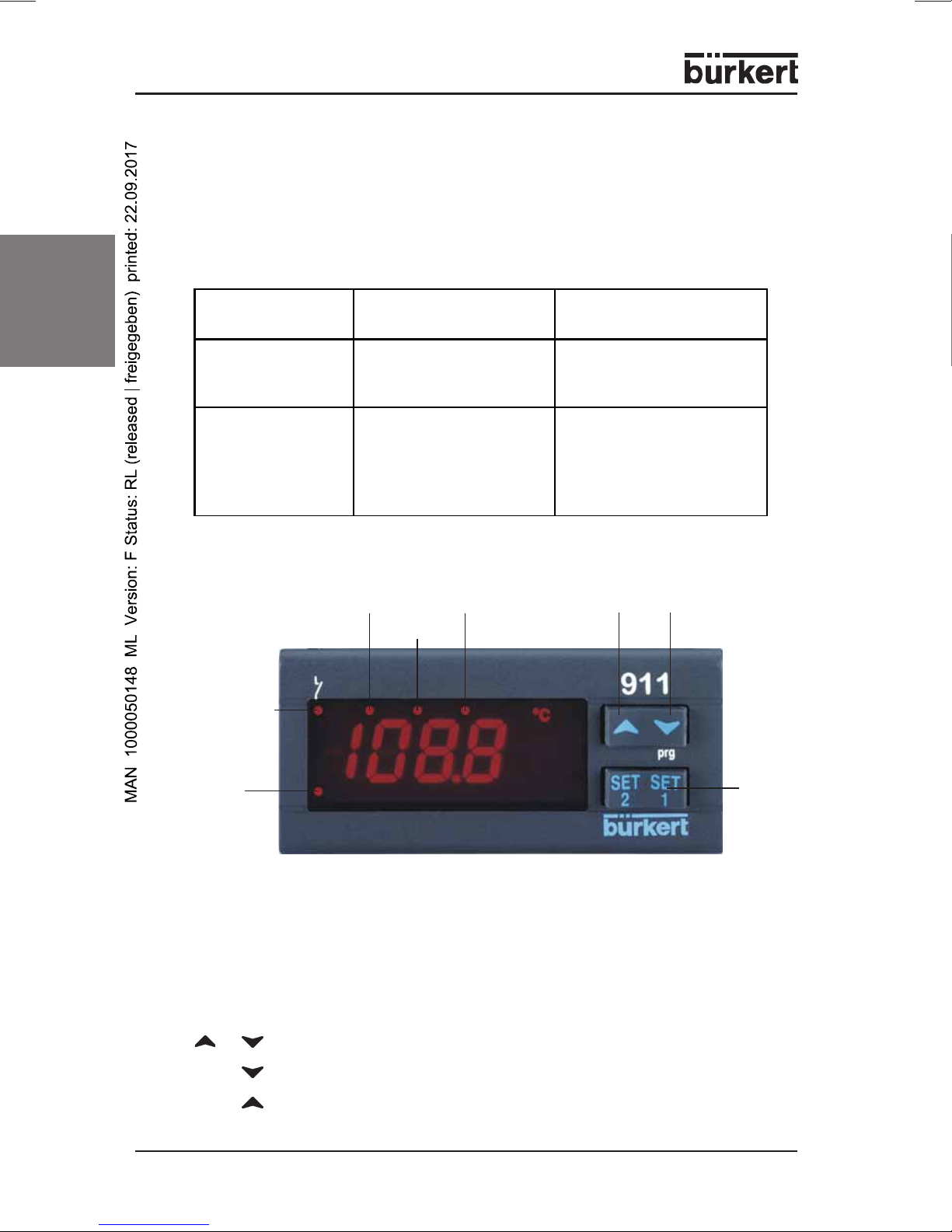
2.2 Operation
Output 1
Alarm
LED
4 ... 20 mA
0 ... 1 V
0 ... 10 V
LED1
ES LED
LED 2
0 = °C; 1 = °F
2 = % RH
3 = bar
4 = PSI
5 = without units
upwards
downwards
SET
button
BUTTONS
SET Display of the set-value,
Changing and confirming a default during the programming phase
BUTTON COMBINATIONS
+
SET+ Selecting the programming level
SET+ Return to the room temperature display
4 - 0911
Locking and unlocking the keypad
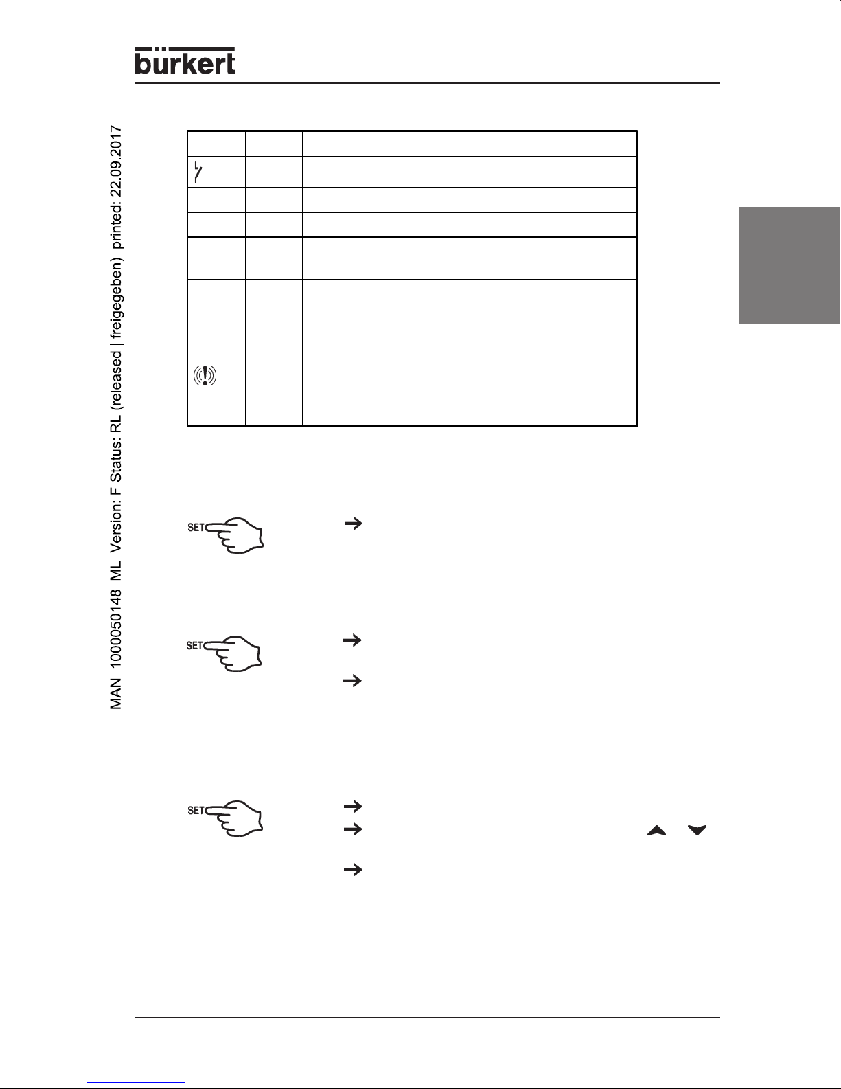
LED MESSAGES
LED Mode Meaning
on Output active
LED1 blinks Programming level (blinks together with LED2)
LED2 blinks Programming level (blinks together with LED1)
E.S. on
Alarm
LED on
SWITCH DEVICE ON/OFF
SET-VALUE DISPLAYS
Energy-saving mode (second set-value) has
been activated by the digital input
- Signals an Alarm state
- If you are in the lower programming level
"Pr2", which can only be accessed using
a password, the lighting up of the Alarm LED
signals that the displayed parameters can
also be accessed in the first level Pr1
(without password).
english
Hold the SET button down for at least 4 sec
(only for parameter OnF = yes).
Briefly press the SET button once. The set-value
display appears in the display.
Briefly press the SET button again, or wait 5
seconds in order to display the room temperature.
CHANGE THE SET VALUE
Hold the SET button down for 2 seconds.
Change the set-value within 10 s with the or
buttons.
You can save the new set-value by briefly pressing
the SET button or by waiting 10 seconds.
0911 - 5
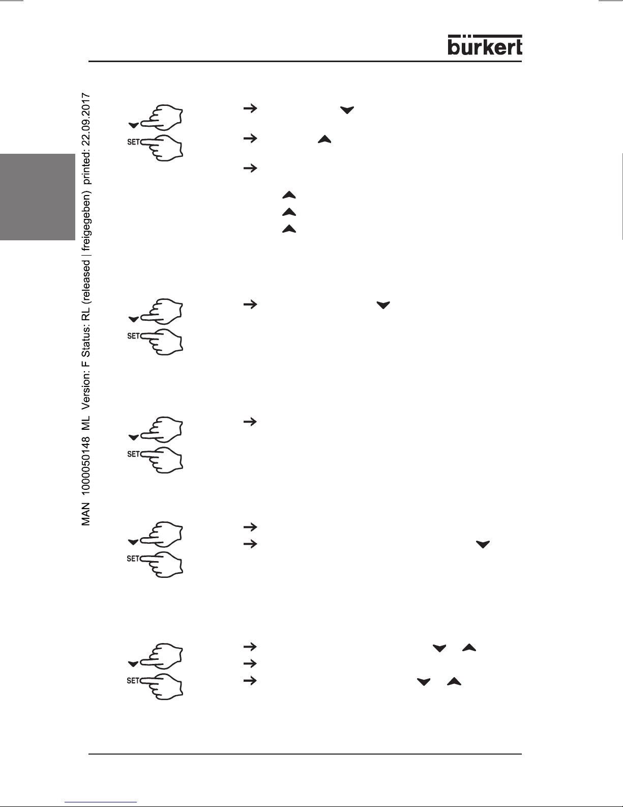
ENTER PROGRAMMING LEVEL
english
USER LEVEL PR1
Hold the SET + buttons down for at least 3
seconds
Select with Pr2 and then confirm with the SET
button.
Enter the password 321 and then confirm with the
SET button.
Enter the „3“ and then 1x SET button
Enter the „2“, and then 1x the SET button
Enter the „1“, and then 1x the SET button
You are now in the Parameter List.
Press down the SET + buttons for 3 seconds.
PR1 contains all the parameters accessible to the
user. The device shows the first parameter that is
available in the user level.
SERVICE LEVEL PR2 (PASSWORD 321)
See:
Accessing the programming level.
ADDING/REMOVING PARAMETERS IN THE USER LEVEL „PR1“
Accessing the programming level
The status can be changed with the SET +
buttons.
If a parameter is not visible in the PR1 level, this will
be indicated by an LED point.
CHANGING THE DEFAULT PARAMETERS
Enter a desired value with SET + or .
Then confirm with the SET button.
Enter a desired parameter with or .
6 - 0911
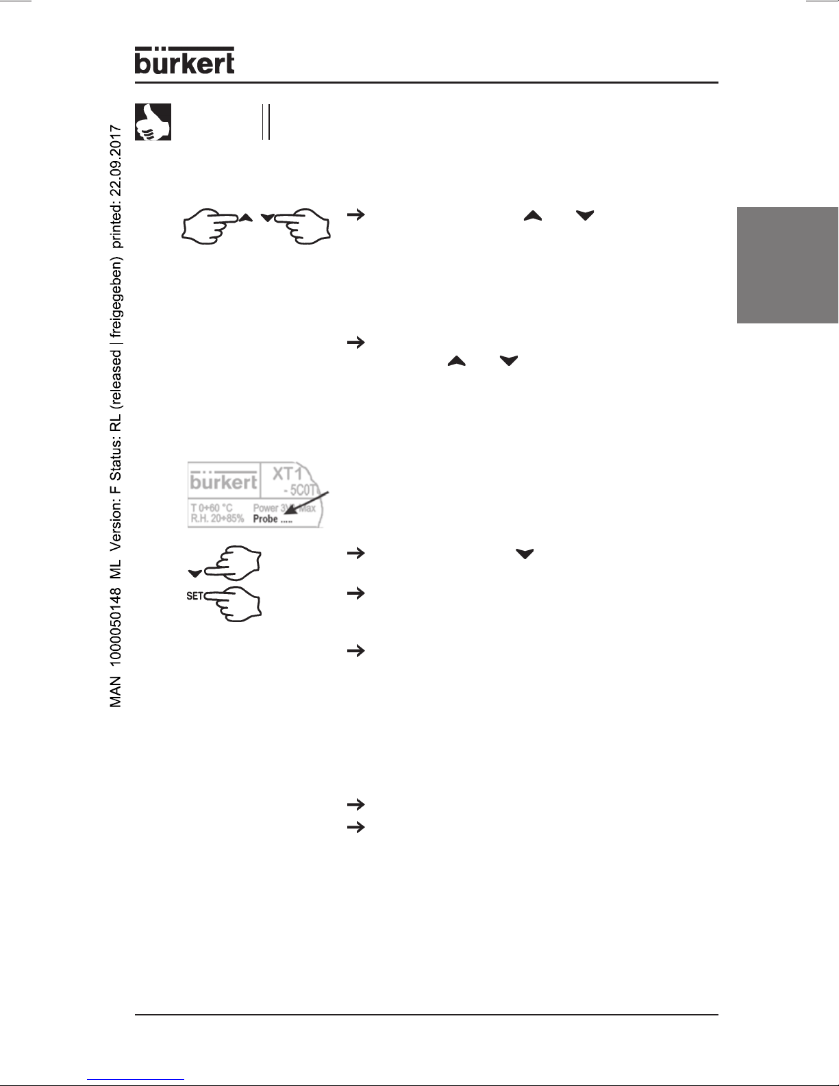
NOTE
All parameter values can be seen by repeatedly pressing the
SET buttons.
LOCKING AND UNLOCKING THE KEYPAD
2.3 Before the installation
PREDEFINE THE SENSOR TYPE
The configurable input type is noted on the controller
label. Please enter this input type if it does not
corresponds to the connected sensor type.
Hold down the buttons and for at least 3
seconds. The POF message appears on the
display.
The keyboard is locked. You can only view the
set-value and the minimum and maximum
temperature. The POF message also appears if you
hold down a button for longer than 3 s.
The keyboard will be unlocked if you hold down
the buttons and for 3 s. POn appears in the
display for a few seconds.
english
Hold down the SET + button for at least 3
seconds.
Select the parameter Pbc (sensor type) and then
confirm with the SET button to see the current
default.
Type TU (temperature controller):
J = Thermoelement J; Pt = Pt100;
C = Thermoelement K; Ptc = PTC;
S = Thermoelement S; ntc = NTC
Type AU
(control devices with voltage/current input):
cur = 4...20 mA; 0-1 = 0...1 V; 10 = 0...10 V
Confirm the default with the SET button.
Briefly switch off the power to the device.
0911 - 7
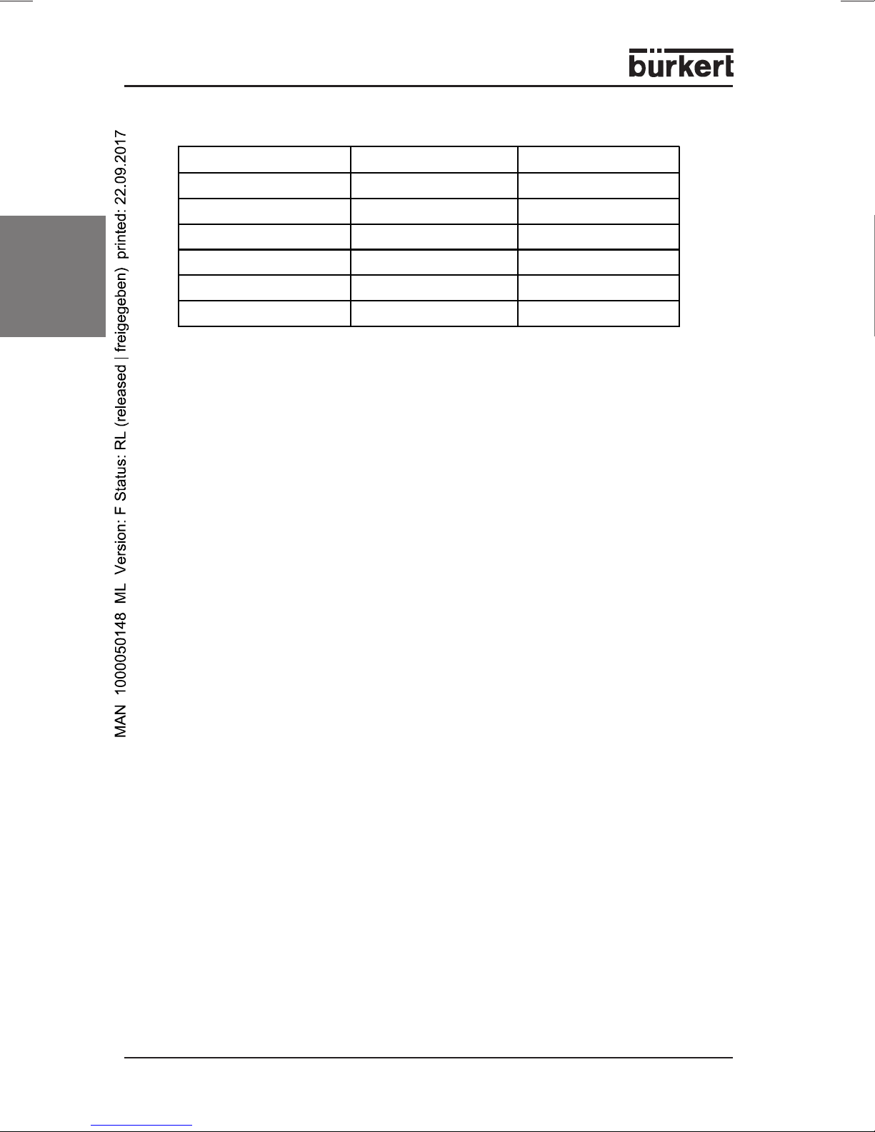
MEASUREMENT LIMITS FOR THE SENSOR TYPES
Sensor Lower limit Upper limit
NTC -40°C 110°C
PTC -50°C 150°C
Pt100 -200°C 600°C
TcK 0°C 1300°C
TcJ 0°C 600°C
english
2.4 Parameters
Control
Hy1
LS1
US1
S1C
AC
on
ono
TcS 0°C 1400°C
Hysteresis 1
Lowest set-value setting
Highest set-value setting
control effect
Minimum switch duration
Minimum switch-on period
Minimum delay
Switch hysteresis of Set-value 1 with
positive or negative values. The default
range is dependent on the input type.
The parameter may not be entered as
zero.
Set-value limits for operator
Set-value limits for operator
in = inverse (heating, humidification)
dir = direct (cooling, dehumidification)
0...250 sec relay switch-off duration
0...250 sec relay switch-on period
0...120 min; minimum delay between two
activations of the control relay.
Alarms
ALC
Configuration
Temperature alarm
ALL
ALU
ALd
Low temperature alarm
Over-temperature alarm
Alarm delay
at temperature
Overshoot/Undershoot
8 - 0911
rE = relative to the set-value (in Kelvin)
Ab = absolute values (in °C)
If SET - ALL is undershot,
a low temperature alarm will be triggered
after the delay time ALd.
If SET + ALU exceeded, a high
temperature alarm will be triggered after
delay time ALd.
0...999 min; Minimum time in which the
conditions for an alarm situation
must be present.

Alarms
ALH
Hysteresis for the
Limit value alarms
ALL and ALU
dAO
Alarm delay at
with Mains ON
S01
Status of the control relay
with sensor fault
tbA
Status of the control relay
after acknowledgement (by
(any button) in an
alarm situation
AS
Configuration of the alarm
relay at an alarm
Measured value display
LCI
Lower analog
Display value
(-1999...1999)
Automatic alarm acknowledgement:
With high alarm undershot by
ALU - ALH and with low alarm with
under shooting of ALL + ALH
(0.1 K...upper measurement range)
0...23.5 hours; suppression of
Alarms after commissioning.
oFF = opened
on = closed
oFF = Relay deactivated
on = Relay activated
cL = Terminal 4-5 closed
oP = Terminal 4-6 closed
Lower display value for current input
4 mA or with voltage input 1 V
or 10 V (only for inputs 4-20
mA, 0-1V, 0-10 V)
english
UCI
OPb
rES
UdM
PbC
P3F
Upper analog
Display value
(-1999...1999)
calibration of the sensor
Resolution
Units
Type of sensor
Temperature sensor U):
Current / voltage input
(AU)
Third terminal of a
Pt100 sensor
Upper display value for current input
20 mA or for voltage input 1 V or 10 V
(only for the 4-20 mA, 0-1V, 0-10 V
inputs)
regardless of the measurement range
in = only whole numbers
dE = also tenths
ce = hundreths
Display of the units directly in the
illuminated display. Regardless of which
controller type is being used:
see
General description
Type of inout
J = Thermoelement „J“; Pt = Pt100;
C = Thermoelement „K“; Ptc = PTC;
S = Thermoelement „S“; ntc = NTC
cur = 4...20 mA; 0-1 = 0...1 V;
10 = 0...10 V
(if present)
no = Pt100 2-wire wired
yES = Pt100 3-wire wired
0911 - 9

Digital inputs
HES
i1F
english
i1P
did
Miscellaneous
Adr
Temperature increase/
Reduction
Function of the digital
Input
Polarity of the digital
input
Alarm delay time
of the digital input
(1...120 min)
Serial address RS485
(1...247)
Set-value is increased/lowered by HES
during the energy saving phase.
EAL = external alarm; OFF = unused;
bAL = serious external alarm;
Es = Energy saving mode Start/Stop;
onF = switch the device ON/OFF
externally;
C-H = reverse the control effect
CL: active with closed contact
OP: active with opened contact
For i1F = EAL or i1F = bAL.
The corresponding alarm
display or message then takes place
Address for XJ500 recording
system. Identifies the device if it
is linked into a ModBUS-compatible
system.
OnF
Ptb
rEL
Pr2
NOTE
Set device to STAND-BY
Number of the parameter-
no = not possible via keyboard
yes = STAND-BY can be activated by
holding down the SET button of at least
4 sec. During a STAND-BY, OFF is
displayed.
only read-out value
table
Version
Display of the parameters in
only read-out value
display only
Level Pr2
You can access hidden paramaters by holding down the keys
SET + for 3 sec in the programming level HY. The message Pr2
appears.
10 - 0911
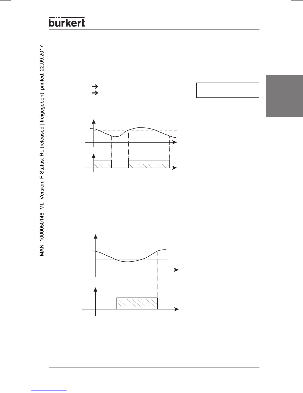
2.5 Controlling the loads
CONTROLLER OUTPUT
The control is dependent on the measured temperature (= sensor
temperature). Program the control direction (heating or cooling) with the
parameter S1C.
S1C = dir Cooling SET = Set-value
S1C = in Heating Hy = Switch hysterisis
COOLING
temperature
SET+HY
SET
t
compressor
ON
t
Parameter S1C = dir; The value HY has been preset to 2 K in the factory.
If the temperature exceeds the value SET + HY, the compressor will be
switched on and will be switched off again when the temperature is below SET.
HEATING
temperature
SET
english
SET-HY
heat
ON
Parameter S1C = in; The value HY has been preset to 2 K in the factory.
If the temperature falls below the value SET-HY, the controller output will be
switched on and will be switched off again when SET is exceeded.
t
t
0911 - 11

3 TECHNICAL DATA
• Housing ABS, self-extinguishing
• Dimensions Front 74 x 32 mm, Depth 60 mm
• Assembly Panel-mounting unit for 29 x 71 mm cutout
• Protection class IP65 from front, only with front seal RG-C
• Connections Screw terminals
• Pipe cross-section ≤ 2.5 mm
english
• Auxiliary energy depending on model
• Power consumption max. 3 VA
• Display three digits, red LED, height 12 mm
• Inputs configurable NTC / PTC or
• Relay outputs Changeover 8(3) A, 250 V AC
• Other outputs acoustic alarm (optional)
• Data memory EEPROM
• Ambient temperature 0 ... +60°C / +32 ... +140°F
• Storage temperature -30 ... +85°C / -22 ... +185°F
• Air humidity 20 ... 85% (non-condensing)
• Measurement range according to sensor
• Resolution 0.1°C or 1°F
• Accuracy at + 25 °C better than 0.5% of the measurement range
IP20
2
12...24 V AC / DC; ± 10%
230 V AC; ± 10%; 50 / 60 Hz
optional 110 V AC; ± 10%; 50 / 60 Hz
NTC / PTC / Pt100 / Thermoelement J, K, S
or 4...20 mA / 0...1 V / 0...10 V
12 - 0911
4 ASSEMBLY, INSTALLATION AND COMMISSIONING
4.1 General information regarding the installation and operation
ATTENTION!
NOTE
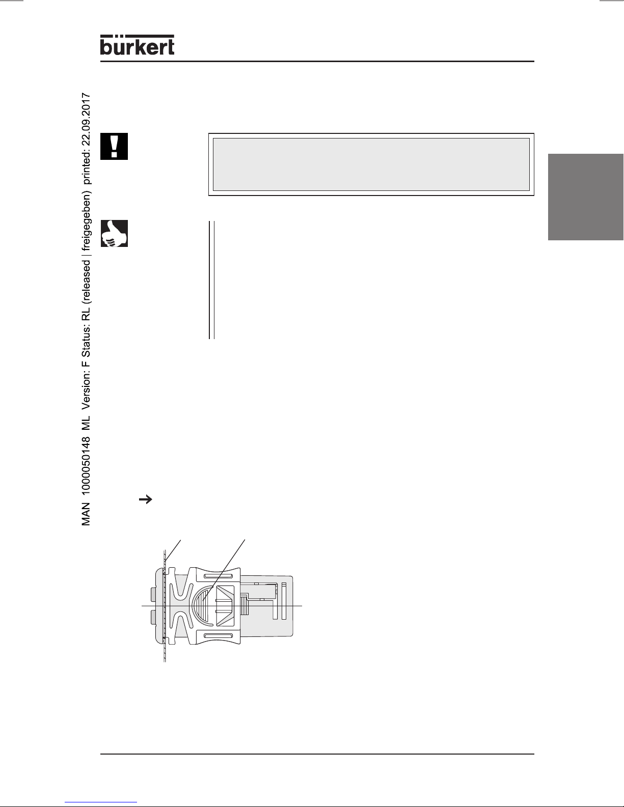
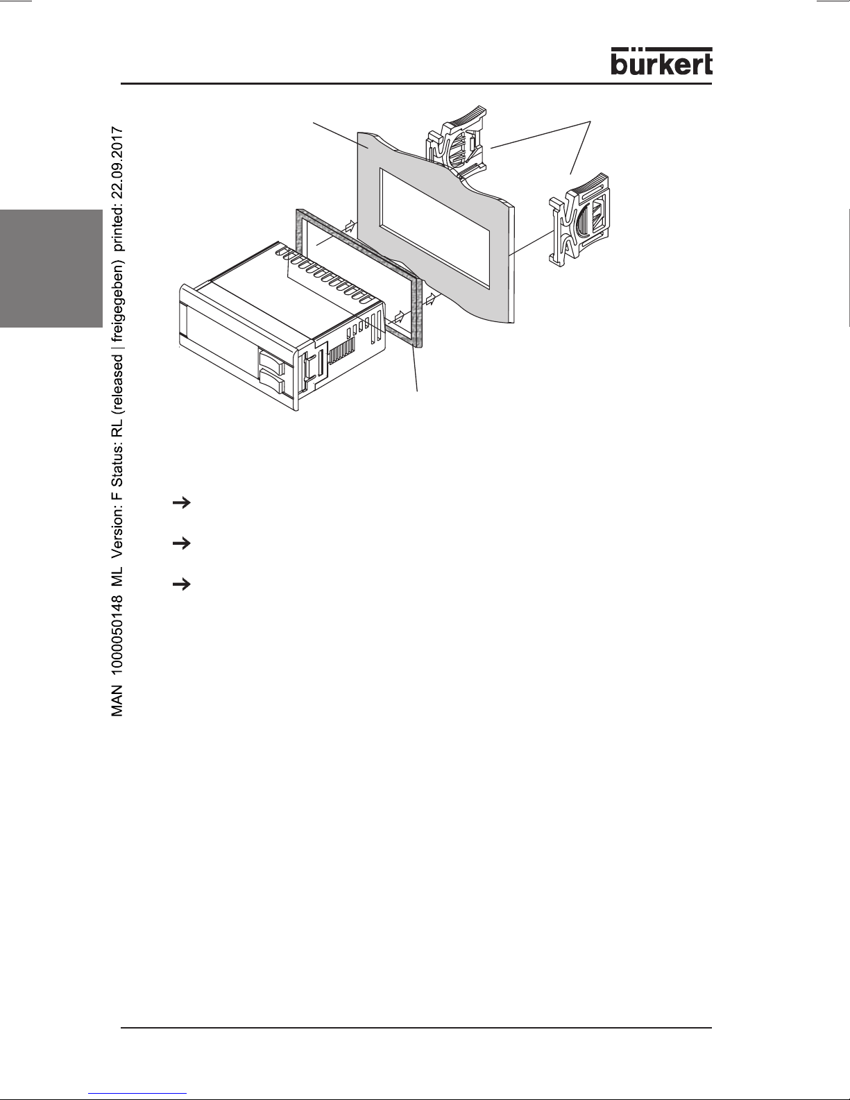
4.2 Assembly
The device is designed for panel mounting in a 71 x 29 mm cutout, and is
secured with a mounting clamp.
In order to guarantee the front protection of IP65, a rubber seal must be fitted
behind the mounting frame (optional for RG-C).
• Do not lay cables for inputs next to lines carrying voltage.
• Avoid heavy vibrations, aggressive gases, heavy soiling
and damp.
• Before connecting the device, check that the power supply
corresponds to the values shown on the rating plate.
• Observe the maximum loading of the relay contacts (see
Technical data
• Ensure that you install all sensors with sufficient separation
from lines carrying voltage, in order to avoid incorrect
temperature measurements and to protect the device from
voltage interference over the sensor inputs.
).
english
Thje ambient temperature form problem-free operation lies in the range from
0 ... +60°C.
Ensure sufficient ventilation through the cooling slots.
Panel
Mounting clamp
0911 - 13
english
4.3 Electrical connections
Use cable with a cross-section of max. 2.5 mm2. The device is provided
with the corresponding screw terminals.
Panel Mounting frame
Front seal
Check the auxiliary energy before you connect the power supply
(see
Technical data
Do not load the relay contacts higher than permitted. If necessary, use a
contactor.
).
14 - 0911
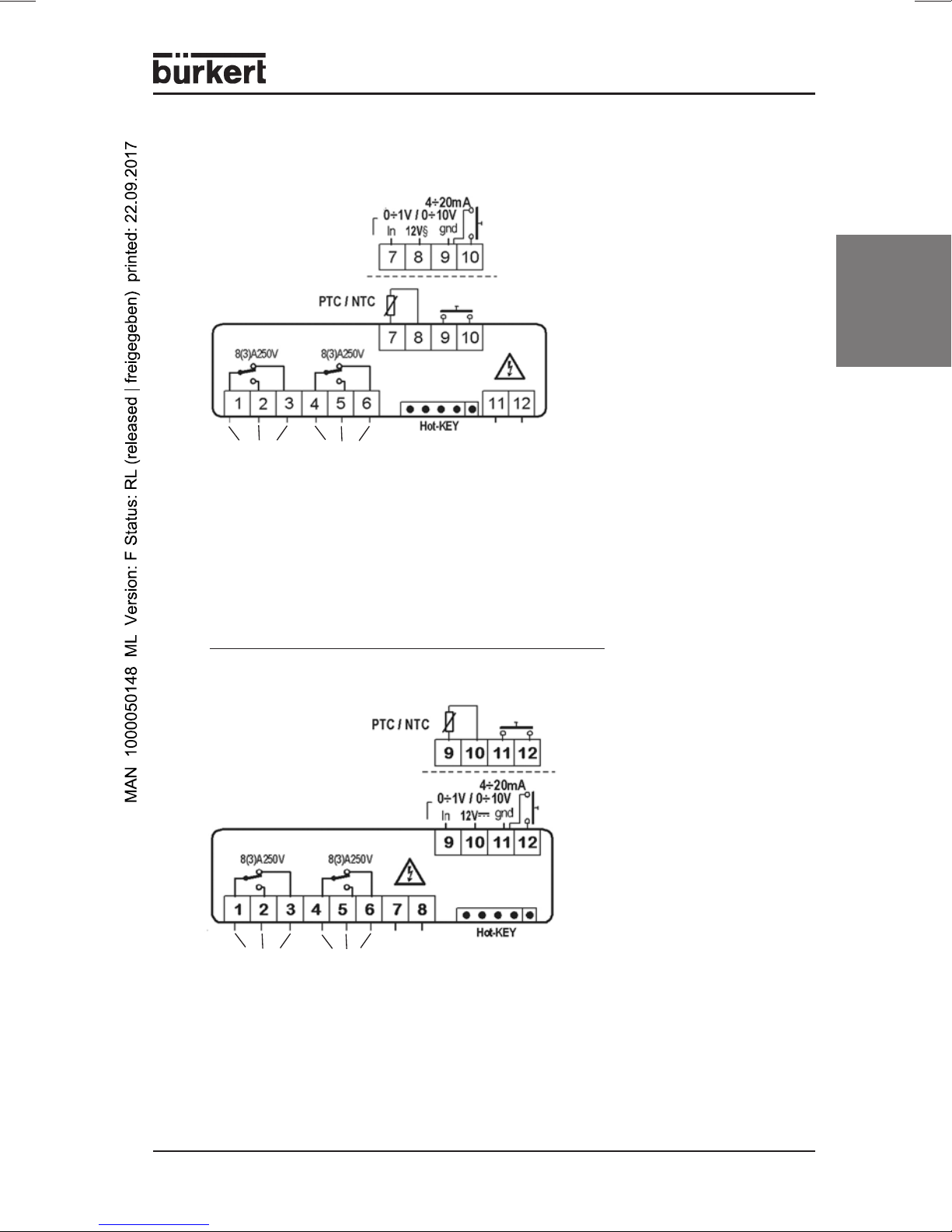
PIN ASSIGNMENT
12 V AC/DC or 24 V AC/DC
english
operating
contacts
(1, 2, 3)
alarm
contacts
(4, 5, 6)
Standard signal input: 0...1 V; 0...10 V = 7(+), 9(-)
4...20 mA = 7(+), 9(-)
Thermoelement J, K, S = 7(+) - 9(-)
sensor: Pt100 = 7 - 9(8)
voltage supply: 24 V AC/DC = 11 - 12
230 V AC
operating
contacts
(1, 2, 3)
Standard signal input: 0...1 V; 0...10 V = 9(+), 11(-)
Thermoelement J, K, S = 9(+) - 11(-)
sensor: Pt100 = 9 - 11(10)
voltage supply: 230 V AC = 7 - 8
alarm
contacts
(4, 5, 6)
4...20 mA = 9(+), 11(-)
0911 - 15
5 HOT-KEY function
DOWNLOAD (HOT-KEY CONTROL DEVICE)
Writing the stored parameter set from the HOT-KEY into the control device:
Switch off the electrical power to the controller, or set it to STAND-BY.
Insert the HOT-KEY up to the stop in the marked position on the controller.
Re-activate the controller.
english
The default parameters in the HOT-KEY will be automatically written into the
controller. During this time, the message DoL blinks in the display. The
programming procedure is finished after 10 seconds, and normal operation
starts automatically with the new parameter set.
The HOT-KEY can be removed.
The following messages are possible at the end of the data transfer:
end for a correct data transfer
err for a failed data transfer
In this case, briefly switch off the power to the device to repeat the
procedure. If you want to cancel the procedure, simply remove the HOTKEY.
UPLOAD (CONTROL DEVICE HOT-KEY)
Writing the current default parameters of the control device into the HOT-KEY:
Insert the HOT-KEY into the provided position when the controller is
switched on again.
Operate 1x with . The message uPL can be seen in the display.
Press the SET button in order to start the data transfer. uPL starts to blink.
You can remove the HOT-KEY again after about 10 seconds.
The following messages are possible at the end of ther data transfer:
end for a correct data transfer
err for a failed data transfer
In this case, press the SET button again to repeat the procedure. If you
want to cancel the procedure, remove the HOT-KEY.
16 - 0911

6 FACTORY SETTING
1
PA
Description Range Default PE
SET Set-value LS1 + US1 0 Pr1
HY1 Switch hysterisis 1
LS1 Lowest set-value 1
US1 Largest set-value 1
dependent on measurement
range
Lower measurement range +
SET1
Upper measurement range +
SET1
-1 Pr1
min Pr2
max Pr2
S1C Control effect Output 1 in = inverse; dir = direct in Pr2
Ac Delay time for the relay 0...250 sec 0 Pr2
Minimum switch-on time
on
for a relay
0...250 sec 0 Pr2
Minimum waiting time
between two consecutive
ono
activations of the same
0...120 min 0 Pr2
load
Alarm limits are absolute
ALC
values or related to the
rE = relative; Ab = absolute rE Pr2
set-value
2
english
ALL
ALU
ALH
ALd
dAO
Lower Alarm Limit
(ALC = rE; ALC = Ab)
Upper Alarm Limit
(ALC = rE; ALC = Ab)
Switch hysterisis for
temperature alarms
Alarm delay time during
the operation
Alarm delay time after
commissioning
dependent on measurement
range
dependent on measurement
range
dependent on measurement
range
0...999 min 15 Pr2
0...23.5 h 1.3 Pr2
10 Pr2
10 Pr2
2Pr2
So1 Output 1 for sensor error oFF = open; on = closed oFF Pr2
tbA
AS
LCI
1
Parameter
2
Programming level
3
Only for devices with voltage and current input
Alarm relay can be
acknowledged
Polarity of the Alarm
relay
Lower analog display
3
value
no; yES yES Pr2
CL...oP oP Pr2
depending on sensor var. Pr2
0911 - 17

PA
UCI
1
3
Description Range Default PE
Upper analog display
value
2
depending on sensor var. Pr2
english
Opb Sensor calibration
depending on measurement
range
0Pr1
rES Resolution in = NO; dE = 0.1; cE = 0.01 in Pr2
Type TU: °C = °C, °F = °F;
UdM Units
Type AU: 0 = °C, 1 = °F;
2 = RH, 3 = bar, 4 = PS,
var. Pr1
5 = without display
Pt = Pt100; J = tcJ; c = tck;
PbC Type of sensor
S = tcS; Ptc = PTC;
ntc = NTC; 0.1 = 0...1 V;
var. Pr1
10 = 0...10 V; cur = 0...20 mA
rd
P3F 3
sensor present no = no; yES = yes no Pr2
HES Energy-saving mode Down scale / Full scale 0 Pr2
i1F
i1P
did
Configuration of the
digital input
Polarity of the digital
input
Alarm delay of the digital
input
c-H / oFF / off / HES /
EAL / bAL
cL = closed;
oP = open
0...120 min 0 Pr2
EAL Pr2
cL Pr2
Adr Serial address for XJ500 RS485 address 1 Pr2
OnF
Activate Standby
function
Ptb Parameter table Read value - Pr2
rEL Software version Read value - Pr2
Pr2 Parameter access to Pr2 Read value 321 Pr1
1
Parameter
2
Programming level
3
Only for devices with voltage and current input
7 MAINTENANCE
When operated in accordance with the instruction in this handbook, the 0911
controller is maintenance-free.
no = no; oFF = active no Pr2
18 - 0911
 Loading...