

AZZA PT-6SBT, SiS5600 User Manual

PT-6SBT
PENTIUM II
AT MAINBOARD
USER’S MANUAL
DOC NUMBER UM-SBT-E1.................................................................PRINTED IN TAIWAN

SiS5600
AT
PENTIUM II MAINBOARD
USER’S MANUAL
DOC NUMBER UM-SBT-O1.................................................................PRINTED IN TAIWAN

SiS5600 Pentium II AT MAINBOARD TABLE OF CONTENTS
i
TABLE OF CONTENTS
Chapter & Section Page
1. INTRODUCTION ...........................................................................................1-1
1.1 OVERVIEW .................................................................................................1-1
1.2 MAINBOARD LAYOUT ...........................................................................1-2
1.3 SPECIFICATIONS ......................................................................................1-3
2. INSTALLATION.............................................................................................2-1
2.1 UNPACKING ...............................................................................................2-1
2.2 AMAZING WAYS TO POWER ON THE PC SYSTEM........................2-2
2.3 POWER OFF THE PC SYSTEM..............................................................2-4
3. HARDWARE SETUP ....................................................................................3-1
3.1 INSTALLING THE DRAM MODULES................................................3-1
3.2 CONNECTORS............................................................................................3-2
3.3 JUMPERS .....................................................................................................3-15
4. AWARD BIOS SETUP .................................................................................4-21
4.1 GETTING STARTED ................................................................................4-21
4.2 MAIN MENU...............................................................................................4-22
4.3 CONTROL KEYS.......................................................................................4-22
4.4 STANDARD CMOS SETUP.....................................................................4-23
4.5 BIOS FEATURES SETUP ........................................................................4-24
4.6 CHIPSET FEATURES SETUP ................................................................4-27
4.7 POWER MANAGEMENT SETUP..........................................................4-32
4.8 INTEGRATED PERIPHERALS ..............................................................4-38
4.9 PNP/PCI CONFIGURATION ...................................................................4-41
4.10 LOAD SETUP DEFAULTS ....................................................................4-44
4.11 SUPERVISOR PASSWORD / USER PASSWORD ...........................4-45
4.12 IDE HDD AUTO DETECTION.............................................................4-46
4.13 SAVE & EXIT SETUP............................................................................4-47
4.14 EXIT WITHOUT SAVING.....................................................................4-48

SiS5600 Pentium II AT MAINBOARD
ii
SOMETHING IMPORTANT !
¶ TRADEMARKS
All trademarks used in this manual are the property of their respective owners.
¶ LOAD SETUP DEFAULTS
“LOAD SETUP DEFAULTS” is the function which will have the BIOS default
settings loaded into the CMOS memory, these default settings are the best-case
values that should optimize system performance and increase system stability .This
function will be necessitated when you receive this mainboard, or when the system
CMOS data is corrupted. Please refer to the Section 4-10 for the details.
¶ DISCHARAGE CMOS DATA
Whenever you want to discharge the CMOS data or open the system chassis, Make
sure to disconnect the AC power first because there is always the 5V standby voltage
connected to this mainboard when using an ATX switching power supply. Without
disconnecting the AC power connector from the PC system, the mainboard may be
damaged by any improper action . Please refer to the Section 3-3 for details.
¶ WAKE ON LAN
In order to support the Wake On LAN feature, the system requires a ATX type SPS
(switching power supply) and it must be able to provide at least 700 mA of driving
capability on the “5V standby” voltage. Please refer to the Section 3-3 for details.
¶ WARNING !
The "Static Electricity" may cause damage to the components on the mainboard, In
order to avoid the damage to the mainboard accidentally, please discharge all static
electricity from your body before touching this mainboard.
¶ NOTICE
The information contained in this manual is subject to change without notice.
IMPORTANT
:
In case that you make a wrong BIOS setup and you can not power on
the PC system, you may press and hold the "INSERT" key and then
press the PW button to turn the system power on. When you are using
such way to power on you PC system, the system BIOS will force the
PC system running at the slower speed and then you may trigger the
BIOS setup program and select the proper parameters for the
mainboard. ( such feature is valid for both AT and ATX power )

SiS5600 Pentium II AT MAINBOARD INTRODUCTION
1-1
1. INTRODUCTION
1.1 OVERVIEW
This mainboard is the AT form-factor with A.G.P. (Accelerated Graphics Port) and PCI
Local Bus on board, designed based on the SiS5600, SiS5595 system chipset. It is a
high performance Pentium™ II personal computer mainboard with 100MHz ultra high
Front Side Bus (FSB) frequency. It is designed for the high performance Pentium™ II
or Celeron™ processor 233 MHz, 266 MHz, 300 MHz, 333MHz, 366MHz, 400MHz,
450MHz and up to 500MHz. (The clock ratio selectable can be up to 8X on the board.)
The jumper-free feature is designed on the board and you don't have to make any
jumper or switch setting when installing the CPU. For example, when you are installing
the CPU onto the mainboard, the system board will detect the CPU type and decide the
proper Voltage. As for the CPU frequency, you can choose to have the system board
detect the CPU type and decide the frequency for you, or you may use the BIOS setup
program to select the CPU clock by yourself.
Two channels “PIO” and “Ultra DMA/33 Bus Master” mode PCI IDE ports, one
Floppy Disk control port, two high speed Serial ports (UARTs) and one multi-mode
Parallel port and supports PS/2™ mouse, IR and USB ports are built on the board..
The Pentium™ II and Celeron™ Processor are the 64-bit processors with RISC
technology, which offer several key features such as built-in 128/256KB/512KB L2
cache (some Celeron does not have L2 cache), 12-stage super-pipeline architecture, out
of order execution .... etc. In order to optimize of its performances, the 32-bit Operating
System (such as Windows® NT and OS/2™) and 32-bit applications are recommended.
The Accelerated Graphics Port (A.G.P.) on the mainboard is designed for AGP 3D
video display card. Unlike PCI-based display cards, the AGP technology provides
lightning data throughput to fully facilitate the 3-Dimensional and multimedia graphics
display. The data transfer rate on AGP can be up to 133Mhz and which is much faster
than the traditional 33MHz PCI VGA card.
SiS5600 Pentium II AT MAINBOARD INTRODUCTION
1-2
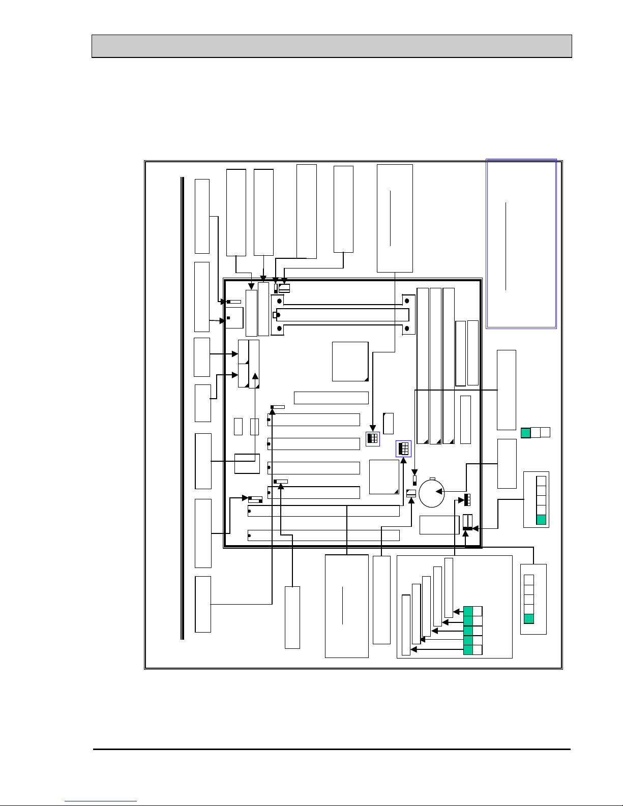
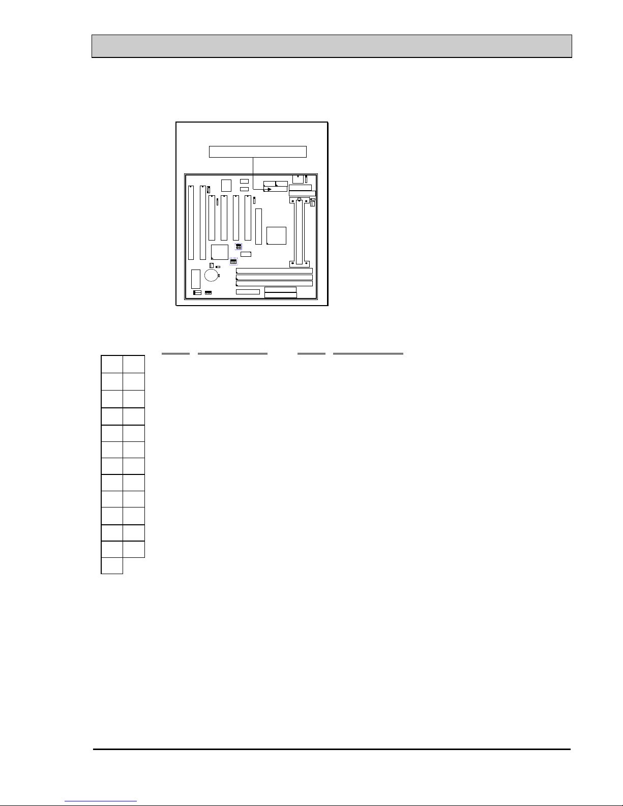
1.2 MAINBOARD LAYOUT
Mainboard Layout with Quick Installation
ISA SLOT
ISA SLOT
PCI SLOT
K/B
PCI SLOT
PCI SLOT
CN3
CN4
Battery
COM2
CN5
LPT
COM1
JP5~JP8
Select CPU clock ratio
Please refer to jumper setting
JP2, JP3,JP4
Select CPU clock
Please refer to jumper settings
CN6,CN7
USB
CN12
IR Port
CN2
PS/2 Mouse
CN13 CPU Fan
CN1
AT K/B
JP9 Clear CMOS
1
2
3
1-2: Normal Setting
2-3: Clear CMOS
CN14
AT Power
CN16
WOL
CN17 Chassis Fan
CAUTION!
Wrong type of USB cable will destroy
either the USB device or the M/B.
Please always handle the USB cable
carefully when installing USB devices.
DIMM 2
DIMM 1
DIMM 3
CN8 FDC
CN9 IDE1
CN10 IDE2
SLOT1
AGP
CN15
ATX Power
1
G G
SS
1
1 1
RS
(Reset button)
HL
(HDD LED)
TL
(Turbo LED)
PW
(Power SW)
“G” =GND,
“S” =Singal
G
1
SL
(Sleep LED)
1
2
3
4 5
KBLOCK
SPK
Connector
1 2 3 4
JP1 K/B OnNow sel.
PCI SLOT

SiS5600 Pentium II AT MAINBOARD INTRODUCTION
1-3
1.3 SPECIFICATION
¥ CPU
Intel Pentium™ II processor and Celeron™ processor.
1. When the FSB clock is 66 MHz, it supports 233 MHz up to 533 MHz CPUs.
2. When the FSB clock is 100 MHz, it supports 350 MHz up to 500 MHz CPUs.
¥ CPU VCC
Switching Voltage Regulator onboard, supports +1.30V DC ~ +3.5V DC Vcore.
Note : The CPU Core Voltage will be Detected and adjusted automatically by the
mainboard, so there is no jumper setting required to select the CPU
voltage.
¥ WORD SIZE
Data Path : 8-bit, 16-bit, 32-bit, 64-bit
Address Path : 32-bit
¥ PC SYSTEM CHIPSET
SiS5600 and SiS5595 system chipset.
¥ SUPER I/O CHIPSET
FDC37C669
¥ FRONT SIDE BUS FREQUENCY
66.6, 75, 83.3,,95, 100, 112, 124, 133MHz (Selected by system BIOS).
¥ MEMORY
DRAM : Three 168 pin DIMM sockets onboard, support 3.3V SDRAM DIMM
modules. Max. memory size : 768MB
CACHE: 256KB or 512KB L2 Cache memory built-in Pentium™ II
processor.
0KB or 128KB L2 Cache memory in Celeron™ processor.
¥ BIOS
AWARD System BIOS.
(2MB Flash ROM, supports Plug & Play, ACPI, DMI and Green functions).
¥ EXPANSION SLOTS
AGP Slots : 32-bit x 1 (Supports 1x or 2x AGP graphics cards)
PCI Slots : 32-bit x 4 ( All Master/Slave, PCI 2.1 Compliant )
ISA Slots : 16-bit x 2 (One of the slot is PCI/ISA shared)

SiS5600 Pentium II AT MAINBOARD INTRODUCTION
1-4
¥ POWER CONNECTOR
AT and ATX power connectors are both designed on the mainboard.
¥ WOL PORTS
One WOL connector supports Wake-On-LAN
¥ USB PORTS
Two Universal Serial Bus (USB) ports.
¥ IDE PORTS
Two channels of Ultra DMA/33 Bus Master IDE ports, which will support up to 4
IDE devices like IDE hard disk, ATAPI CD-ROM etc. The IDE ports can be
programmed to support PIO Mode 4, DMA mode 2 and Ultra DMA/33.
¥ SUPER I/O PORTS
1. Supports PS/2 Mouse connector, PS/2 Keyboard connector (optional) and AT
Keyboard connector.
2. Two high speed NS16C550 compatible serial ports (UARTs).
3. One SPP/EPP/ECP parallel port.
4. One Floppy Disk Control port.
¥ IR PORT
One HPSIR and ASKIR or Fast IR (optional) compatible IR port.
¥ HARDWARE MONITORING
1. Monitor the system voltages, CPU temperature, and two cooling fan speeds.
2. Supports LDCM (optional).
¥ ACPI ( This feature is valid only when ATX power supply is connected )
Advanced Configuration and Power Interface (ACPI) function is strongly
recommended by PC’98 because it will let you have many additional features and
that will make your PC system becomes very friendly and convenient. Followings
are the ACPI features designed on the board:
1. Power on the system by panel-switch
2. Power on the system by RTC alarm
3. Power on the system by modem Ring-in signal
4. Power on the system by LAN signal.( Wake On LAN )
5. Power on the system by Keyboard (Optional).
6. Resumed by Modem ring-in, RTC alarm, .... etc..
7. Supports Full-On/Doze/Standby/Suspend operating modes.
8. Power off (soft-off) by OS (active with ATX SPS only) or Panel-switch.

SiS5600 Pentium II AT MAINBOARD INTRODUCTION
1-5
¥ DIMENSION
4-layers PCB, 220mm x 240mm (Baby-AT Form-Factor)..
¥ ENVIRONMENT LIMIT
1. Operating Temperature : 10 to 40. (50 to 104)
2. Required Airflow : 50 linear feet per minute across CPU.
3. Storage Temperature : - 40 to 70. (- 40 to 158)
4. Humidity : 0 to 90% non-condensing.
5. Altitude : 0 to 10,000 feet.

SiS5600 Pentium II AT MAINBOARD INSTALLATION
2-1
2. INSTALLATION
2.1 UNPACKING
The mainboard contains the following components in the package. Please inspect the
following contents and confirm that everything is there in the package. If anything is
missing or damaged, call your supplier for instructions before proceeding.
l This mainboard.
l One USER‘S MANUAL.
l One Cable set for peripheral devices.
l One Pentium™ II Processor Retention Mechanism (CPU Holder).
l One CD diskette for device drivers and utility programs.
This mainboard contains electrostatic sensitive components and it can be easily
damaged by static electricity. So please leave it sealed in the original packing until
when installing.
A grounded anti-static mat is recommended when unpacking and installation. Please
also attached an anti static wristband to your wrist and have it grounded to the same
point as the anti-static mat.
After the opening of the mainboard carton, please observe the mainboard carefully to
make sure there is no shipping and handling damage before you can start to install the
PC system.

SiS5600 Pentium II AT MAINBOARD INSTALLATION
2-2
2.2 AMAZING WAYS TO POWER ON THE PC SYSTEM
Basically, you can connect either AT or ATX power supply to this mainboard. When
the ATX power supply is connected, there are many ways to power on the system.
Please read the following description for the details.
¨ POWER BUTTON
The power button on the front panel is not only for power-on and power-off the PC
system. It can programmed by COMS setup program and it has different features.
Please refer to Section 3-2 for the detail of function description.
¨ KEYBOARD PASSWORD (optional)
This mainboard allows you to enter your personal password and you can use it to
power on your system. When the system power is off, This mainboard has the
stand-by 5V voltage active and it will keep scanning the keyboard status waiting for
the correct password input to turn on the system power. ( you will see the Keyboard
LED lights when system power is off, it is because the standby 5V is still active.)
When the “Password” is "enabled" in the system BIOS, you will have to reboot the
PC system to activate the setting, when you see the POST (Power On Self Test) is
completed, the setting is changed and stored in the CMOS memory. Having finished
the procedure, you may turn the power off and then you can use the keyboard to
power-on the PC system afterward.
¨ RTC ALARM
PC system can be waked up by the RTC setting in the CMOS. You can set the
alarming date and time in the RTC memory, When RTC alarms, the PC system will
be triggered and wakes up automatically.
Enable the “Power Up by Alarm” selection in the BIOS setup utility, and then input
the accurate date and time in its following fields. (the “Power Up by Alarm” is in
the “POWER MANAGEMENT SETUP” section, please refer to Section 4-7),
Having stored the RTC alarm setting, the PC system will be turned on automatically
according to the date and time which is recorded in the CMOS memory.

SiS5600 Pentium II AT MAINBOARD INSTALLATION
2-3
¨ MODEM RING-IN
This mainboard can be triggered by a modem ring-in signal. When you have a
external modem installed, you can use it to power on the PC system. When there is
the incoming message from te external modem, the PC system will be triggered by
the ring-in signal and wake up automatically to receive the message for you.
In order to use the ring-in signal to wake up your PC system, you will have to use
the EXTERNAL MODEM and have it connected to one of the Serial Ports (COM1
or COM2). When the system power is off, this mainboard will continue to detect the
serial port status. When it detects the ring-in signal from the serial port, the system
power will be turned on and start to receive the incoming messages automatically.
To enable the Modem Ring-In feature, you have to run the BIOS setup utility and
enable the “Ring Power Up Control” option (it is in the “POWER MANAGEMENT
SETUP”, please refer to Section 4-7 for the settings).
Note: This function is not available when using the internal MODEM card.
¨ WAKE ON LAN ( WOL )
There is a WOL connector CN16 (see Section 3-2) on the mainboard which is
designed to connect to the signal from a LAN card which supports the Wake On
LAN feature. When such LAN card is installed, you may use it to turn on the PC
system from your remote server and monitor the PC status.
To enable this feature, you will have to use the BIOS setup utility to enable the
“Ring Power Up Control” (it is located at “POWER MANAGEMENT SETUP”,
please refer to Section 4-7 for the settings).

SiS5600 Pentium II AT MAINBOARD INSTALLATION
2-4
2.3 POWER OFF THE PC SYSTEM
1. When ATX power supply is connected.
There are two ways to power off the system.
a) Shut Down by Power Button
b) Shut Down by OS”. (such as Windows® 95 and Windows® 98, you can choose
the Shut Down from the file menu and the system will be powered off
immediately ).
2. When AT power supply is connected.
You can not use the power button (PW switch) to turn the system power off. You
can only use the power switch on the power supply to power off the PC system
IMPORTANT:
In case that you make a wrong BIOS setup and you can not power on
the PC system, you may press and hold the "INSERT" key and then
press the PW button to turn the system power on. When you are using
such way to power on you PC system, the system BIOS will force the
PC system running at the slower speed and then you may trigger the
BIOS setup program and select the proper parameters for the
mainboard. ( such feature is valid for both AT and ATX power )

SiS5600 Pentium II AT MAINBOARD AWARD BIOS SETUP
3-1
3. HARDWARE SETUP
Before you can start to install this mainboard, some hardware settings is required
to make sure it will work perfectly with the component which you are going to
install in your PC system. To configure this mainboard is a simple task, only a few
jumpers, connectors, cables and sockets need to be selected and configured.
Please refer to the following sections for the settings.
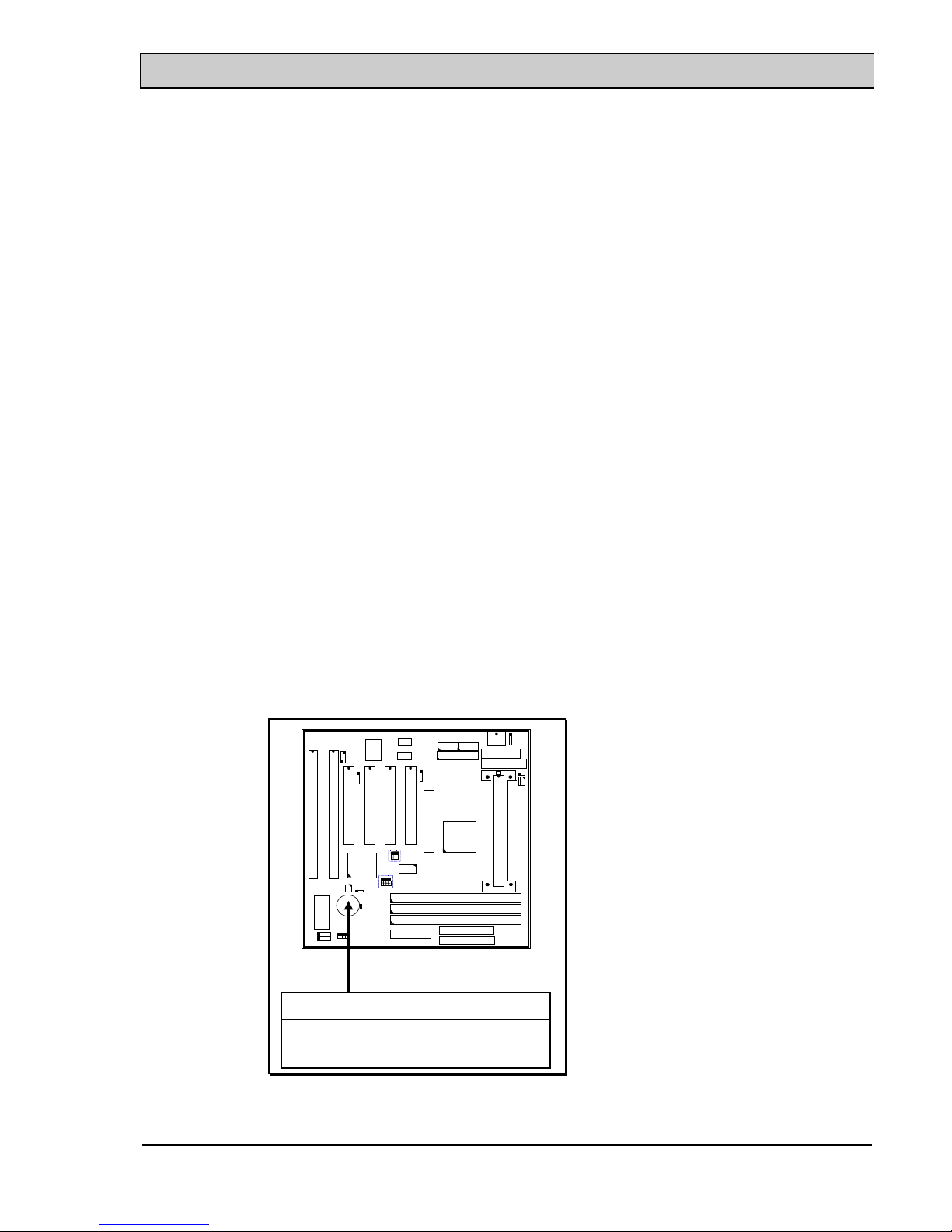
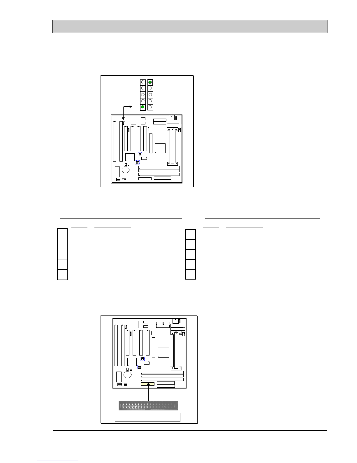
3.1 INSTALLING THE DRAM MODULES
This mainboard integrates a main memory controller that supports a 64-bit DRAM
interface. The DRAM controller supports the following features:
1. DRAM type: Synchronous (SDRAM) DRAM.
2. Memory size: 8MB to 768MB.
3. Memory modules supported: Single and double density 3.3V DIMMs.
ISA SLOT
ISA SLOT
PCI SLOT
K/B
PCI SLOT
PCI SLOT
CN3
CN4
DIMM 2
DIMM 1
DIMM 3
CN8 FDC
CN9 IDE1
CN10 IDE2
SLOT1
AGP
PCI SLOT
DRAM Subsystem Diagram
DIMM 3( BANK4+ BANK5 )
DIMM 2 ( BANK2 + BANK3 )
DIMM 1 ( BANK0 + BANK1 )
When use the SDRAM DIMM modules on the mainboard, the clock of the
memory sub-system will be synchronous with the FSB clock. So please use the
PC-100 compatible DIMM modules when you are using the 100MHz CPU on the
mainboard.
SiS5600 Pentium II AT MAINBOARD AWARD BIOS SETUP
3-2
The memory module suggested on this mainboard will be either EDO or SDRAM
3.3V modules, When you are installing memory modules on the mainboard, you
don't have to start from DIMM 1 first, you can install the memory in any of the
sock which is available. However, if you use this mainboard to upgrade your PC
system and you want to keep your old memory modules. In case that you have
more than one modules and they have different access time. In this case, please
install the slower DIMM module in DIMM1 first and then install the faster ones in
DIMM2 and DIMM3. Please also run the BIOS setup program and select the
parameters which is comply with the slowest module installed on the mainboard.
Note: In order to increase of the system performance and steability, install
memory modules starting from DIMM 1 is recommended
3.2 CONNECTORS
The connectors on mainboard will be used to connect the accessories or peripheral
devices (such as power, mouse, printer,...etc.). Followings are the connectors with
its description and pin assignment which is designed on the mainboard.
(A) BAT1: Battery Socket (Use the 3 Volts Lithium battery : CR2032)
ISA SLOT
ISA SLOT
PCI SLOT
K/B
PCI SLOT
PCI SLOT
CN3
CN4
CN8 FDC
CN9 IDE1
CN10 IDE2
SLOT1
AGP
PCI SLOT
BAT1: Battery Socket
+ Battery Positive
- Ground
SiS5600 Pentium II AT MAINBOARD AWARD BIOS SETUP
3-3
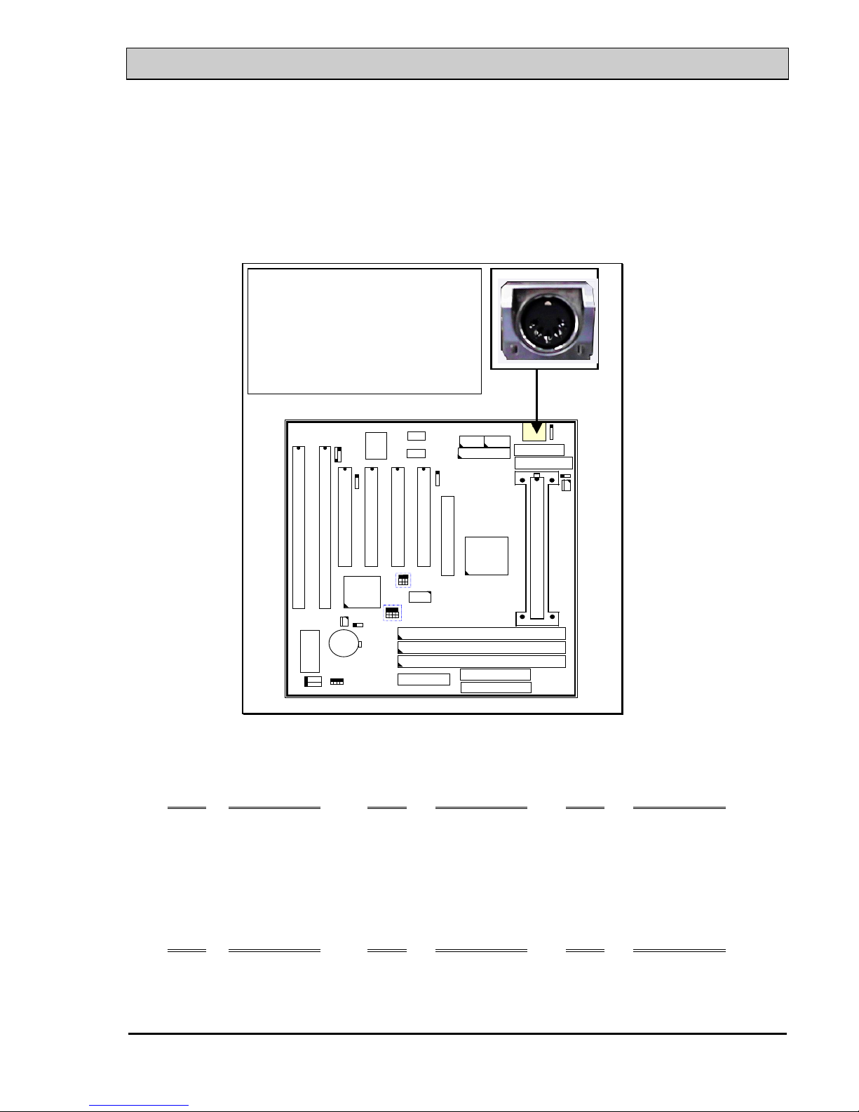
(B) CN1: Keyboard Connectors
Either the PS/2 (CN20) type or the AT (CN1) type keyboard connector can be
installed here, ( only one connector can be installed) The factory default is the AT
type connector installed on the board. When the AT type K/B installed on the
board, the PS/2 type (CN20) become invisible.
K/B CONNECTORS:
Either PS/2 or AT type K/B connector
can be installed on the mainboard.
Basically, these two connectors share
the same space, so there is only one
connector can be installed.
Default: AT type connector installed.
ISA SLOT
ISA SLOT
PCI SLOT
PCI SLOT
PCI SLOT
CN3
CN4
CN8 FDC
CN9 IDE1
CN10 IDE2
SLOT1
AGP
PCI SLOT
Pin assignment of PS/2 keyboard connector: (CN20 is under CN1)
Pin # Signal name
Pin # Signal name Pin # Signal name
1 Keyboard Data 3 Ground 5 Keyboard Clock
2 No Connection 4 + 5V DC 6 No Connection
Pin assignment of AT keyboard connector: (CN1)
Pin # Signal name
Pin # Signal name Pin # Signal name
1 Keyboard clock 3 No connection 5 Keyboard Clock
2 Keyboard data 4 Ground 6 + 5V DC
SiS5600 Pentium II AT MAINBOARD AWARD BIOS SETUP
3-4
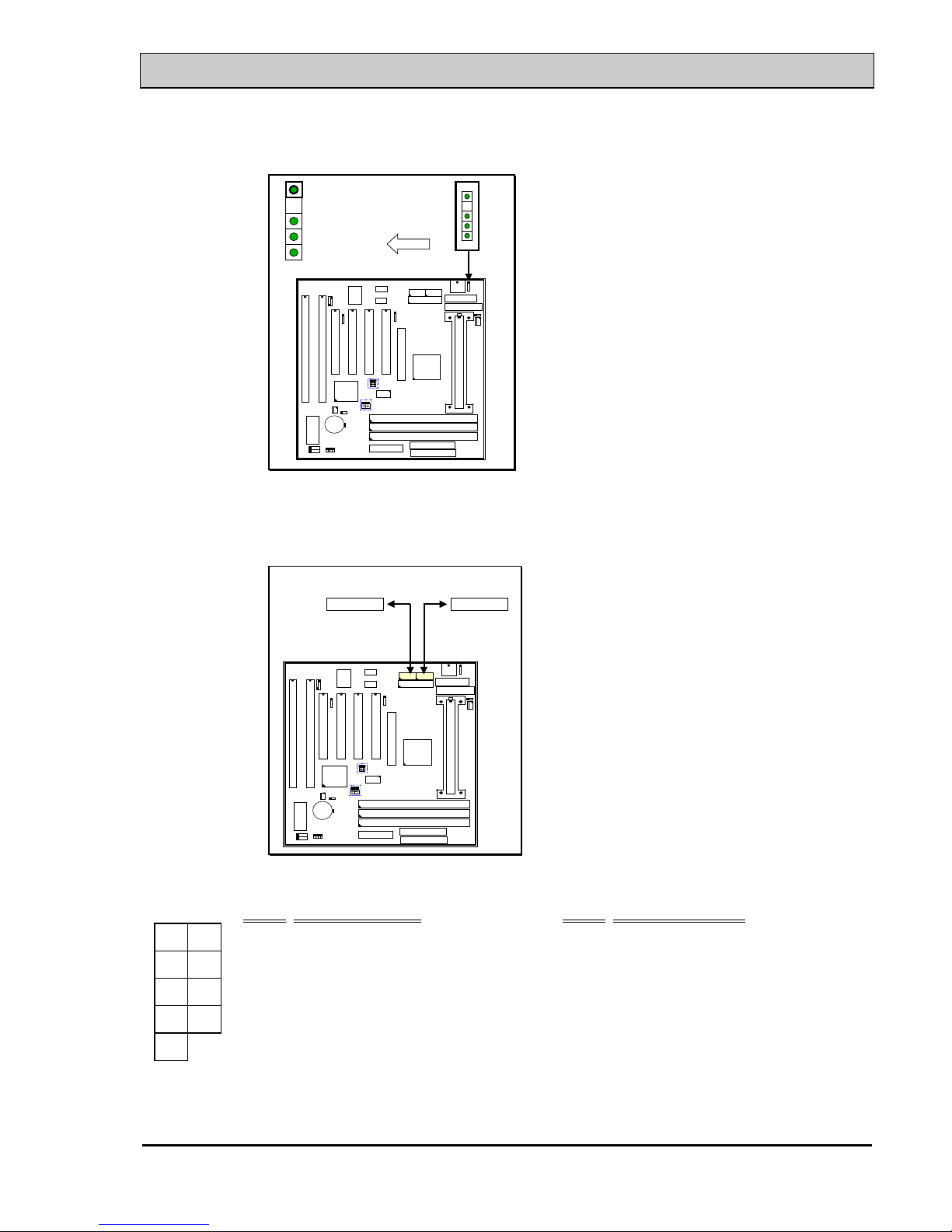
(C) CN2: PS/2 Mouse Connector
1
2
3
4
5
Mouse Data
No Connection
Ground
+5V DC
Mouse Clock
CN 2
ISA SLOT
ISA SLOT
PCI SLOT
K/B
PCI SLOT
PCI SLOT
CN3
CN4
CN8 FDC
CN9 IDE1
CN10 IDE2
SLOT1
AGP
PCI SLOT
(D) CN3: COM 1 (Serial Port 1) Connector
CN4: COM 2 (Serial Port 2) Connector
ISA SLOT
ISA SLOT
PCI SL OT
K/B
PCI SLOT
PCI SL OT
CN8 FDC
CN9 IDE1
CN10 IDE2
SLOT1
AGP
PCI SL OT
CN 3CN 4
COM 1 COM 2
Ping assignment of serial port connector:
1 6 Pin #
Signal name Pin # Signal name
1
DCD (Data Carrier Detect)
6
DSR (Data Set Ready)
2
RD (Received Data)
7
RTS (Request To Send)
3
TD (Transmit Data)
8
CTS (Clear To Send)
4
DTR (Data Terminal Ready)
9
RI (Ring Indicator)
5
Ground
5 9
I/O address 3F8H/2F8H/3E8H/2E8H, IRQ3/IRQ4, selected by CMOS setup.
SiS5600 Pentium II AT MAINBOARD AWARD BIOS SETUP
3-5
(E) CN5: Parallel Port Connector
ISA SLOT
ISA SLOT
PCI SLOT
PCI SLOT
PCI SLOT
CN8 FDC
CN9 IDE1
CN10 IDE2
SLOT1
AGP
PCI SLOT
PARALLEL PORT
CN 5
Pin assignment of parallel port:
114 Pin #
Signal name Pin # Signal name
1
STROBE
14
AUTO FEED
2 Data Bit 0 15
ERROR
3 Data Bit 1 16
INIT
4 Data Bit 2 17
SLCT IN
5 Data Bit 3 18 Ground
6 Data Bit 4 19 Ground
7 Data Bit 5 20 Ground
8 Data Bit 6 21 Ground
9 Data Bit 7 22 Ground
10
ACK
23 Ground
11 BUSY 24 Ground
12 PE 25 Ground
13 SLCT 26 N.C.
13 25
SiS5600 Pentium II AT MAINBOARD AWARD BIOS SETUP
3-6
(F) CN6: USB 1 (Universal Serial Bus) Connector
(G) CN7: USB 2 (Universal Serial Bus) Connector
1
2
3
4
5
5
4
3
2
1
CN 7
USB 2
CN 6
USB 1
ISA SLOT
ISA SLOT
PCI SLO T
PCI SLO T
PCI SLOT
CN8 FDC
CN9 IDE1
CN10 IDE2
SLOT1
AGP
PCI SLO T
Pin assignment of USB connector:
CN 7 CN 6
Pin #
Assignment Pin # Assignment
●
5 Ground (BLACK WIRE)
●
1+5V DC (RED WIRE)
●
4 Ground (BLACK WIRE)
●
2 DATA- (WHITE WIRE)
●
3 DATA+ (GREEN WIRE)
●
3 DATA+ (GREEN WIRE)
●
2 DATA- (WHITE WIRE)
●
4 Ground (BLACK WIRE)
●
1+5V DC (RED WIRE)
●
5 Ground (BLACK WIRE)
(H) CN8: Floppy Disk Control Port Connector ( using IRQ6, DMA 2):
CN8 FDC Connector
ISA SLOT
ISA SLOT
PCI SLOT
PCI SLOT
PCI SLOT
CN9 IDE1
CN10 IDE2
SLOT1
AGP
PCI SLOT
 Loading...