

AZZA P4X2-AV, P4XA-AV, P4XA-BV User Manual

The AZZA P4X Mainboard Series
Cover Click Here
Table Of Contents Click Here
Introduction Click Here
Hardware Installation Click Here
BIOS Management Click Here
R

P4X Mainboard Series
P4X Mainboard Series
P4X Mainboard SeriesP4X Mainboard Series
SOCKET 478 DDR ATX Mainboard
P4X2
P4X2----AV
P4X2P4X2
P4XA
P4XA----AV
P4XAP4XA
P4XA
P4XA----BV
P4XAP4XA
AV
AVAV
AV
AVAV
BV
BVBV
Version 1.x
UM-P4X-2AABV-E1
Rev 1.0V
Creation Date: 22 November 2001
The AZZA P4X MAINBOARD SERIES
Page 1

User’s Notice
Copyright
This publication c ontains information that is protec ted by co pyright. No part of it
may be reproduced in any form or by any means or used to make any transformation adaptation without prior written permission from the copyright holders. This
publication is provided for informational purpos es only. The manufacturer makes
no representations or warranties with respect to the contents or us e of this manual and specifically disclaims any e xpress or implied war ranties of m erchantability
or fitness for any particular p urpose. The user w ill assume the entire risk of th e
use or the results of the use of this document. The manufacturer reserves the
right to revise this publication and make changes to its conte nts at any time, without prior notice.
2001. All Rights Reserved.
Trademarks
Trademarks
Trademarks
Microsoft®, MS-DOS®, Windows
tered trademarks of Microsoft Corporation. Intel® Pentium
trademark of Intel Corpor ation. Award is the r egistered tra demark of Award S oftware, Inc. Other trad emarks and register ed trademarks of products appearing in
this publication are the properties of their respective holders.
This package contai ns t he fol l owi n g i t ems:
•
Mainboard
•
Users manual
•
One IDE cable
•
One 34-pin floppy disk drive cable
•
One Driver Utility CD
If any of these item s are d amage d or mis sing, pl ease co ntac t your dealer or sales
representative for assistance.
If you require additional inf ormation or assistance durin g installation please contact your dealer. Your dealer
TM
, Windows® 95 and Windows® 98 are regis-
Package Checklist
Package Checklist
Package Checklist
Technical Support
Technical Support
Technical Support
will be able to provide the latest information.
TM
4 is a registered
Page 2
The AZZA P4X MAINBOARD SERIES

Table of Contents
Chapter 1:- Introduction
1.1. Mainboard Layout ..................................................................................... 5
1.2. Mainboard Overview ................................................................................. 6
1.2.1. Mainboard Series ...................................................................................6
1.2.2. Mainboard Dimensions ...........................................................................6
1.2.3. Environmental Limitations .......................................................................6
1.3. Features and Specifications ...................................................................... 7
1.4. System Health Monitor Functions ............................................................. 9
1.5. System Intelligence .................................................................................. 10
Chapter 2:- Hardware Installation
2.1. Installation Checklist ................................................................................ 11
2.2. Installation Steps ...................................................................................... 12
2.3. Expansion Cards, Connectors and Jumpers ............................................... 13
2.4. CPU, Memory and Expansion Slots ............................................................ 14
2.4.1. Installation of the CPU ............................................................................14
2.4.2. Memory Modules ....................................................................................14
2.4.3. PCI Slots ...............................................................................................15
2.4.4. AGP (Accelerated Graphics Port) Slot .......................................................15
2.4.5. CNR (Communications Network Riser) Slot ..............................................16
2.5. Internal Connectors .................................................................................. 16
2.5.1. Floppy Disk Drive (FDC) .........................................................................16
2.5.2. Primary and Secondary IDE Connectors ...................................................16
2.5.3. Standard Infrared Connector ..................................................................17
2.5.4. CPU and Chassis Fa n Connectors ............................................................17
2.5.5. ATX Power Supply Connectors ................................................................17
2.5.6. WOL (Wake-On-LAN) and WOM (Wake-On-Modem) Connectors ...............18
2.5.7. CD Audio In Connector ...........................................................................19
2.5.8. USB 3, USB 4, USB 5 and USB 6 Connectors ............................................19
2.5.9. SMB Connector ........................................................................................20
2.6. System Panel Buttons and LED Connectors .............................................. 20
2.6.1. PW: Power On/Off and External Suspend Switch Connector .......................20
2.6.2 Standby LED Connector ...........................................................................21
2.6.3. IDE HDD LED Connector ........................................................................21
2.6.4. Reset Button Connector ...........................................................................21
Page 5
Page 11
The AZZA P4X MAINBOARD SERIES
Page 3

Table of Contents
2.7. Speaker and Power LED Connector ........................................................... 21
2.7.1. Speaker Connector ..................................................................................21
2.7.2. Front Panel Power LED Connector ............................................................ 21
2.8. External Connectors .................................................................................. 22
2.8.1. PS/2 Keyboard Connector .......................................................................22
2.8.2. PS/2 Mouse Connector ...........................................................................22
2.8.3. COM 1 and COM 2 Connectors ................................................................22
2.8.4. Parallel Port Connector ........................................................................... 22
2.8.5. USB 1 and USB 2 Connectors ..................................................................23
2.8.6. Audio Game Port Connector .................................................................... 23
2.9. Jumper Settings ........................................................................................ 23
2.9.1. JP1: Keyboard Power .............................................................................23
2.9.2. JP2: USB1 and USB2 Power ....................................................................24
2.9.3. JP4 and JP5: CPU FSB Selection ..............................................................24
2.9.4. JP13: Clear CMOS Memory .....................................................................24
Chapter 3:- Managing The PC BIOS
3.1. AWARD BIOS CMOS Setup Utility ........................................................... 25
3.2. Main Menu .............................................................................................. 25
3.3. Standard CMOS Setup ............................................................................ 26
3.4. Advanced BIOS Features ........................................................................ 28
3.5. Advanced Chipset Features .................................................................... 31
3.6. Integrated Peripherals ........................................................................... 34
3.7. Power Management Setup ..................................................................... 38
3.8. PNP/PCI Configuration .......................................................................... 41
3.9. PC Health Status .................................................................................... 42
3.10. Frequency/Voltage Control .................................................................... 43
3.11. Load Fail-Safe Defaults .......................................................................... 44
3.12. Load Optimized Defaults ........................................................................ 45
3.13. Set Supervisor Password ........................................................................ 45
3.14. Set User Password .................................................................................. 46
3.15. SAVE & EXIT SETUP/EXIT WITHOUT SAVING ........................................ 47
Page 25
Page 4
The AZZA P4X MAINBOARD SERIES
Introduction
Chapter 1
Chapter 1
Chapter 1
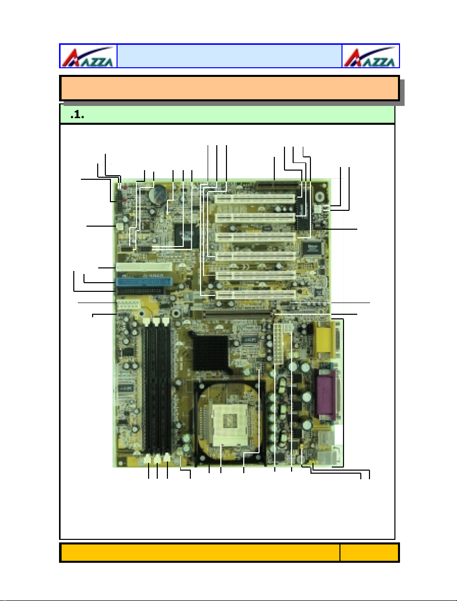
1.1. Mainboard and PC99 ATX External Connector Layout
LED Connectors
CN 8: FDD
CN 15-C: ATX 12V Power Su pply
Speaker
Power LED
System Panel and
CN 17:
Chassis Fan
CN 10: IDE 2
CN 9: IDE 1
CN 42: SMB
CN 38: USB 6
CN 31: USB 4
JP13: Clear
CMOS
CN 32: USB 5
-
Introduction
-
Introduction
-
Introduction
CN 30: USB 3
PCI 3
PCI 2
PCI 1
PCI 5
PCI 6
CNR Slot
PCI 4
CN 16: WOL
CN 24: WOM
CN 12: IR
CN 21: CD-IN
AGP Slot
PC 99 ATX Connec tor
JP4/JP5: CPU FSB
Fan
Heat Sink Brac ket
CN 13: CPU
DIMM 1
DIMM 2
DIMM 3
Selection
CPU 478 Socket
CN15-B: ATX 12V
Power Supply
CN 15-A: ATX 12V
Power Supply
The AZZA P4X MAINBOARD SERIES
JP2: USB 1, 2
Power
JP1: K/B Power
Page 5
Introduction
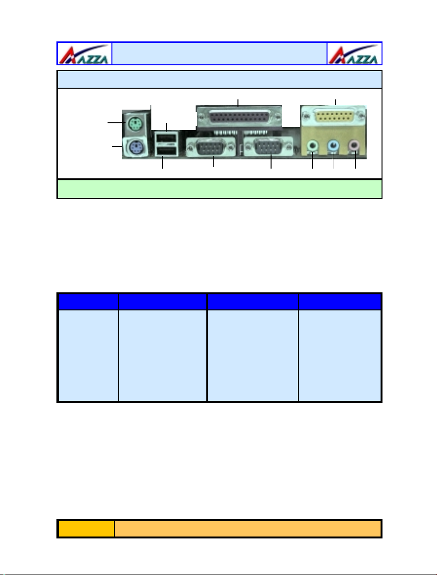
PC 99 ATX External Connector
CN 5: LPT CN18: Game/MIDI Port
CN 2: PS/2 MS
CN 1: PS/2 KB
CN 7: USB 2
CN 6: USB 1 CN 3: COM 1 CN 4: COM 2
SPK-OUT LINE-IN MIC-IN
1.2. Mainboard Overview
1.2.1. Mainboard Serie s
The mainboards in this manual are all Pentium 4 platforms that use a VIA chipset.
This manual describes three different models. They are:
i) P4X2-AV
ii) P4XA-AV
iii) P4XA-BV
The differences between these models are shown in the table below.
Model P4X2-AV P4XA-AV P4XA-BV
Northbridge P4X266 P4X266A P4X266A
Southbridge VT8233 VT8233 VT8233A
USB (1.1) 6 6 4
CNR Slot Yes Yes No
IDE ATA 100 100 133
JP4 & JP5 No Yes Yes
1.2.2. Mainboard Dimensions
Width & Length: 305 mm x 230 mm
1.2.3. Environmental Limitations
Operati ng Temper ature: 10°C to 40°C . (50°F to 104°F)
Required Airflow: 50 linear feet per minute across CPU.
Storage Temperature: - 40°C to 70°C. (- 40°F to 158°F)
Humidity: 0 to 90% non-condensing.
Altitude: 0 to 10,000 feet
Page 6
The AZZA P4X MAINBOARD SERIES

Introduction
1.3. Features and Specifications
Processor
Supports Intel® Socket 478 Pentium 4.
Chipset
P4X2-AV
P4XA-AV
P4XA-BV
I/O Chipset
For hardware monitoring: Winbond W83697HF
: VIA P4X266 + VT8233
: VIA P4X2 66A + VT8233
: VIA P4X266A + VT8233A
CPU Switching Voltage Regulator
Equipped with a switching voltage regulator that automatically detec ts +1.10V to
+1.85V DC power supply.
System Memory
• 3.0GB DRAMs for registered DDR SDRAM modules.
• 1.5GB DRAMs for unbuffered DDR SDRAM modules.
• Three 184-pin DIMM sockets.
• Supports PC1600 a n d PC2100 DDR SDRAM
Expansion Slots
These mainboards are equipped with six dedicated PCI slots, one CNR slot (not
available on the
P4XA-BV
) and one 4x AGP slot.
Onboard Audio Features
Supports Microso ft Di rectSound/ Direct Sound 3D and AC97 Fu l l Dupl ex.
Word Size
• Data Path: 8-bit, 16-bit, 32-bit, 64-bit
• Address Path: 32-bit
BIOS
• 2Mb Flash ROM
• Award BIOS, Windows 95/98 Plug and Play (PnP) compatible.
• Supports SCSI sequential boot-up.
• Flash EPROM for easy BIOS upgrades.
• Supports DMI 2.0 function
The AZZA P4X MAINBOARD SERIES
Page 7

Introduction
Desktop Management Interface (DMI)
The mainboard comes with DMI 2.0 built into the BIOS. The DMI utility in the
BIOS will automatically record differ ent information about your system configuration and store this information in the DMI poo l, which is a part of the system
board's Plug and Play BIOS. DMI, along with the appropriately networked software, is designed for easy inventory, maintenance and the simplified troubleshooting of computer syst ems.
WOL (Wake-On-LAN) Port
One WOL connector supports Wake-On-LA N f unc tionality.
WOM (Wake-On-Modem) Port (optional)
One WOM connector supports Wake-On-Modem functionality.
USB Ports
USB allows data exchange between your computer and a wide range of
simultaneously accessible external Plug and Play peripherals. The
P4XA-AV
P4XA-BV
and USB 2 are external connectors. They can be found on the PC 99 ATX
connector. The other USB co nnectors are inter nal connectors and can be used to
connect other USB devices. (Cables for the internal connectors are sold
separately).
Please note that the internal USB connectors are non-standard. When
you purchase the cabl e please ensure that the connector on on e side of
the cable is compat ib l e with t he in t ernal USB co nnecto r a nd th e conn ector on the other side of the cable is a standard USB connector.
models are equipped with
model is equipped with
(version 1.1) USB connectors. The
six
(version 1.1) USB connectors. USB 1
four
P4X2-AV
and
Connectors
•
Two IDE connectors.
•
One floppy drive interface supports up to two 2.88MB floppy drives.
•
One 20-pin ATX 12V po wer supply connector.
•
One 2x2 ATX 12V po we r supply connector.
•
One 1x6 ATX 12V po we r supply connector.
•
CPU and chassis fan connectors.
•
One CD audio-in connector.
•
One system management bus (SMB) connector.
Page 8
The AZZA P4X MAINBOARD SERIES
Introduction
ATX Double Deck Ports (PC 99 color-coded connectors))
•
Two USB ports.
•
Two external DB-9 serial port connectors:
•
One SPP/ECP/EPP DB-25 parallel port.
•
One mini-DIN-6 PS/2 mouse port.
•
One mini-DIN-6 PS/2 keybo ard port.
•
One game/MIDI port.
•
Three audio jacks: speak-out, line-in and mic-in.
PCI Bus Master IDE Controll er
•
Two PCI IDE interfaces support up to four ID E devic es.
•
The
P4X2-AV
ATA/100 hard drives.
•
The
P4XA-BV
hard drives.
•
PIO Mode 3 and Mode 4 Enhanced IDE (data transfer rate up to
16.6MB/sec.).
•
Bus mastering reduces CPU utilization during disk transf er .
•
Supports ATAPI CD-ROM, LS-120 and ZIP.
IrDA Interface
The mainboard is equipped with an IrDA connector for wireless connectivity between your compute r and peripheral devi ces. It supports peripheral devices that
meet the HPSIR or ASKIR standard.
and
P4XA-AV
model support ATA/33, ATA/66, ATA/100 and ATA/133
(
Optional
)
models support ATA/33, ATA/66 and
COM 1
and
COM 2
(UART).
1.4. System Health Monitor Functions
The mainboard is capable of monitoring the fo llowing health conditions of your
system:
1. Processor temperature. It has an overheat alarm.
2. VCORE/3.3V/5V/12V/-12V voltages and failure alarm.
3. Processor and chassis fan speeds. It has a failure alarm for these fans.
4. Read back capability that displays temperature, voltage and fan speed.
Only use this utility in Windows ® 95 or Windows ® 98 operating systems.
The Hardware Monitoring System Utility
These mainboards comes with the Hardware Monitoring System utility contained
on the CD. It is capable of monitoring the system’s hardware conditions such as
the temperature of the processor, voltage, and the speed of both the CPU and
chassis fans. You are allowed to manually set a range to the items being
monitored. If the values are over or under the se t range a war ning mess age will
automatically pop up. We recommend that you use the Default Settings, which
are the ideal settings that will maintain the system in a good working cond ition.
The AZZA P4X MAINBOARD SERIES
Page 9

Introduction
1.5. System Intelligence
Dual Function Power Button
Depending on the setting in the Soft-Off By Power-Button field of the Power
Management Setup, this switch allows the system to enter the Soft-Off or
Suspend mode.
External Modem Ring-on (opti onal)
The Modem Ring-on feature allows the system that is in the Suspend mode or
Soft Power Off mode to wake-up/power-on to respond to incoming calls. This
feature s u pports the ext ernal modem on l y.
RTC Timer to Power-on the System
The RTC installed on the system board allows your system to automatically
power-on at a set date and time.
Wake-On-LAN Ready
The Wake-On-LAN function allows the network to remotely wake up a Soft Power
Down (Soft-Off) PC. Your LAN card must support the remote wakeup function.
The 5V SB power source of your power supply must be at least 720mA.
ACPI Ready
The mainboard is designed to meet the ACPI (Advanced Configuratio n and Power
Interface) specification. ACPI has energy saving features that support OS Direct
Power Management (OSPM) for round the clo ck PC operation.
Page 10
The AZZA P4X MAINBOARD SERIES
Hardware Installation
Chapter 2
Chapter 2
Chapter 2
2.1. Installation Checklist
The following is a checklist of all the expansion slots, jumpers and connectors
that should be configured on your mainboard before you can run your pc.
CPU Slot
DIMM Slots
PCI Slots
CNR Slot
AGP Slot
CN8
CN9
CN10
CN12
CN13
CN15-A
CN15-B
CN15-C
CN16
CN17
CN21
CN24
CN30
CN31
CN32
CN38
CN42
Socket 478 CPU Slot which supports Pentium 4
Three 184 pin slots that supports 3 GB DDR SDRAM.
Six 32 bit PCI Slots.
One Communications Network Riser Slot (Not available for P4XA-BV)
One Accelerated Graphics Port Slot
Floppy Disk Drive FDC
Primary IDE IDE1
Secondary IDE IDE2
Infrared IR (optional)
CPU Fan CPU Fan
ATX 12VPower Supply ATX
ATX 12V Power Supply ATX12V
ATX 12V Power Supply AUX3.3V
Wake On Lan WOL
Chassis Fan Chassis Fan
CD-In without housing CD-In
Wake On Modem WOM (optional)
Universal Serial Bus 3 USB3
Universal Serial Bus 4 USB4
Universal Serial Bus 5 USB5 (only for P4X2-AV and P4XA-AV)
Universal Serial Bus 6 USB6 (only for P4X2-AV and P4XA-AV)
System Management Bus SMB (optional)
-
Hardware Installation
-
Hardware Installation
-
Hardware Installation
Installation Checklist
Expansion Slots and Sockets
Internal Connectors
External Connectors
CN1
CN2
CN3
CN4
CN5
CN6
CN7
CN18
PS/2 Keyboard Connector PS/2 KB
PS/2 Mouse Connector PS/2 MS
Serial Port 1 COM1
Serial Port 2 COM2
Parallel Port LPT
Universal Serial Bus 1 USB1
Universal Serial Bus 2 USB2
Game/Audio Port Audio/Game
The AZZA P4X MAINBOARD SERIES
Page 11
Hardware Installation
Installation Checklist (Continued)
PW
S5L
HL
RS
PWR-LED
SPK
JP1
JP2
JP4/JP5
JP13
System Panel Buttons and LED Connectors
Power On/Off and Suspend Switch Connector.
Standby LED Connector
HDD LED Connector
Reset Button Connector
Speaker and Power LED Connector
Power LED
Speaker Connector
Keyboard Power
USB 1 and 2 Power
CPU FSB Selection
Clear CMOS
Jumpers
A Diagram of the Expansion Slots, Jumpers and
Connectors can be seen on the following page
2.2. Installation Steps
•
You need to complete the following installation steps before you
can use your PC.
•
Check and Set the Mainboard Settings.
•
Install the Central Processing Unit (CPU).
•
Install the Memory Modules.
•
Install the Expansion Car ds.
•
Connect the Ribbon Cables, Panel Wires and the Power Supply.
•
Setup the system BIOS
efore you start
B
use a grounded anti-static mat. We further recommend that you attach an antistatic wristband, which is grounded at the same location as the mat, to your
wrist.
installing your mainboard we strongly recommend that you
Only use an ATX 12V Power Supply.
Page 12
The AZZA P4X MAINBOARD SERIES
Hardware Installation
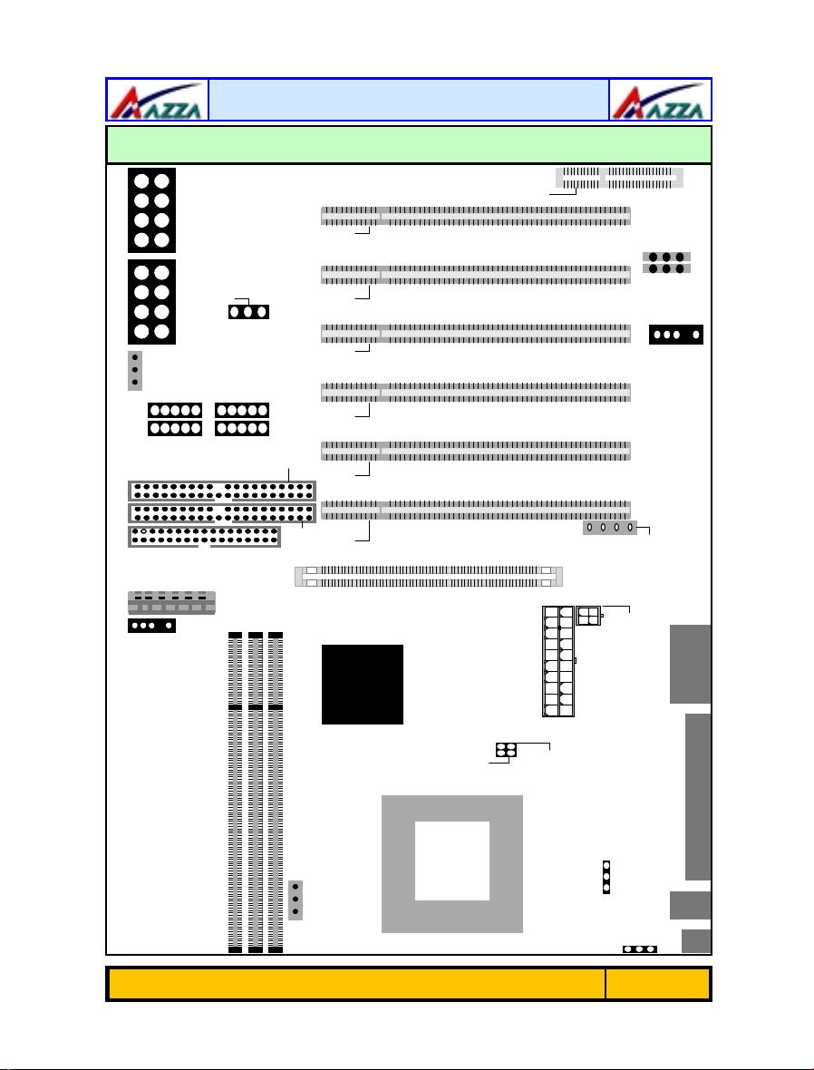
2.3. Expansion Cards, Connectors and Jumpers
1 PWRLED
1 PWRLED
CN17: Chassis Fan1PW S5LHLRS
CN17: Chassis Fan1PW S5LHLRS
1 1 1
1 1 1
CN42: SMB
CN42: SMB
1 SPKR
1 SPKR
1111
1111
CN38:
USB6
CN38:
USB6
CN38:
USB6
1
1
CN32:
USB5
CN32:
USB511
CN32:
USB5
1
1
CNR
CNR
JP13: Clear CMOS
JP13: Clear CMOS
1 DIMM 1
1 DIMM 1
CN31:
USB4
CN31:
USB4
CN31:
USB4
1
1
1
1
FDD
FDD
CN15-C: 1x6 AT X 12V Pow er Sup ply
CN15-C: 1x6 AT X 12V Pow er Sup ply
CN 8:
CN 8:
CN30:
USB3
CN30:
USB311
CN30:
USB3
DIMM 2
DIMM 3
DIMM 2
DIMM 3
1
CN 10:
IDE 2
1
CN 10:
IDE 2
PCI 1PCI 2PCI 3PCI 4PCI 5PCI 6
PCI 1PCI 2PCI 3PCI 4PCI 5PCI 6
CN 9:
IDE 1
CN 9:
IDE 1
12V Power Supply
12V Power Supply
CN 15-A: ATX
CN 15-A: ATX
AGP Slot
AGP Slot
CN24:
WOM
CN24:
WOM
11
11
CN16:
WOL
CN16:
WOL
1CN12:IR
1CN12:IR
CN21: CD-IN
CN21: CD-IN
1
1
CN 15-B: ATX
12V Power Supply
CN 15-B: ATX
12V Power Supply
JP4: CPU FSB
Se le ct io n
JP4: CPU FSB
Se le ct io n
CN13: CPU Fan
CN13: CPU Fan
1
1
1
1
JP5: CPU FSB
Se le ct io n
JP5: CPU FSB
Se le ct io n
The AZZA P4X MAINBOARD SERIES
JP2: K/B PWR
JP2: K/B PWR
1
1
JP1: USB PWR
JP1: USB PWR
Page 13
1
1
Hardware Installation
2.4. CPU, Memory and Expansion Slots
2.4.1. Installation of the CPU
To install your processor, please complete the following set of instructions
1. Locate a small dot marked on the top of the CPU. This mark indicates
Pin 1 of the CPU.
2. Locate Pin 1 for the Socket on the mainboard.
3. There is a lever on the side of the socket. First push this leve r sideways
and then lift it to a 90-degree angle.
4. Insert the CPU into the Socket. Please make sure that Pin 1 for the CPU
is inserted into Pin 1 of the Socket.
5. When the CPU is installed correctly push the lever back into place .
6.
Install a proper heat sink with cooling fan
tion. Failing to install a heat sink with cooling fan may cause overheating which will burnout your CPU and damage your mainb oard. The heat
sink with cooling fan should be installed on the retention mechanism
that is provided. This retention mechanism is designed to hold the bigger Heat Sink that is required for the Pentium 4 CPU.
for proper heat dissipa-
Heat Sink and Retention Mechanism
You must use an Intel approv ed Heat Sink. This CPU op erates at a very
high frequency and therefore heats up very quickly. (A normal heat sink
will not be adequate to cool the CPU and the CPU will burn-out.) These
heat sinks are very heavy. A retention mechanism for the Heat Sink has
been provided with the mainboard.
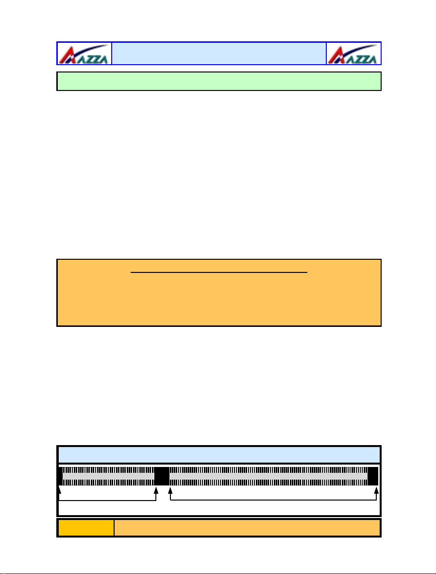
2.4.2. Memory Modules
These mainboards all have three 184-pin DDR SDRAM slots. If registered DDR
SDRAM modules are used then they can support a maximum of 3 GB DRAM. If
unbuffered DDR SDRAM modules are used they c an support a maximum of 1.5
GB DRAM
The DDR SDRAM slots are located o n the right hand side of the b oard. To install
the DIMM’s into these slots, make sure the white lever at each side of the slot
has been pulled down to an angle of approximately 45°. Make sure that the
DIMM is in the correct or ientation. Place the DIMM on the slot and push down
firmly.The white levers will come back up and lock the module in plac e .
Page 14
Top View of a 184-pin DIMM Slot
52 pins 40 pins
The AZZA P4X MAINBOARD SERIES
 Loading...