

AZZA P4X4-ALH User Manual
The P4X4-ALH Mainboard
Page 1
P4X4-ALH
Mainboard Manual
Socket 478 DDR333 ATX Mainboard
Version 1.x
UM-P4X4-ALH-E1
Rev 1.0V
Creation Date: 02 August 2002

The P4X4-ALH Mainboard
Page 2
Copyright
This publication contains information that is protected by copyright.
No part of it may be reproduced in any form or by any means or used
to make any transformation adaptation without prior written permission from the copyright holders. This publication is provided for informational purposes only. The manufacturer makes no representations
or warranties with respect to the contents or use of this manual and
specifically disclaims any express or implied warranties of merchantability or fitness for any particular purpose. The user will assume the
entire risk of the use or the results of the use of this document. The
manufacturer reserves the right to revise this publication and make
changes to its contents at any time, without prior notice.
2002. All Rights Reserved.
Trademarks
Microsoft
®
, MS-DOS®, WindowsTM, Windows®95 and Windows®98 are
registered trademarks of Microsoft Corporation. Intel
®
PentiumTM4 is a
registered trademark of Intel Corporation. Award is the registered
trademark of Award Software, Inc. Other trademarks and registered
trademarks of products appearing in this publication are the properties of their respective holders.
Package Checklist
This package contains the following items:
• Mainboard
• User’s manual
• One IDE cable
• One 34-pin floppy disk drive cable
• One 4 CH out cable
• One Driver Utility CD
If any of these items are damaged or missing, please contact your
dealer or sales representative for assistance.
Technical Support
If you require additional information or assistance during installation
please contact your dealer. Your dealer will be able to provide the latest information.
User’s Notice

The P4X4-ALH Mainboard
Page 3
Chapter 1:- Introduction
Page 5
1.1. Mainboard and PC 99 ATX External Connector Layout ...............................5
1.2. Overview .......................................................................................................6
1.2.1. The P4X4-ALH Mainboard ...................................................................6
1.2.2. Mainboard Dimensions ..........................................................................6
1.2.3. Environmental Limitations ......................................................................6
1.3. Features and Specifications .........................................................................6
1.4. System Health Monitor Functions ................................................................9
1.5. System Intelligence ......................................................................................9
Chapter 2:- Hardware Installation
Page 10
2.1. Installation Checklist ...................................................................................10
2.2. Installation Steps ......................................................................................... 11
2.3. Expansion Slots, Jumpers and Internal Connectors ...................................12
2.4. CPU, Memory and Expansion Slots ..............................................................13
2.4.1. Installation of the CPU ..........................................................................13
2.4.2. Memory Modules ..................................................................................13
2.4.3. PCI Slots ..............................................................................................14
2.4.4. AGP (Accelerated Graphics Port) Slot ......................................................14
2.5. Internal Connectors .....................................................................................15
2.5.1. Floppy Disk Drive Connector ..................................................................15
2.5.2. Primary and Secondary IDE Connectors ..................................................15
2.5.3. Infrared Connector (Optional) ................................................................15
2.5.4. CPU Fan and Chassis Fan Connectors .....................................................16
2.5.5. ATX Power Supply Connectors ...............................................................16
2.5.6. CD-IN/AUX-IN Connector .......................................................................17
2.5.7. WOL (Wake-On-LAN) Connector ............................................................17
2.5.8. S/PDIF Connector (Optional) .................................................................17
2.5.9. USB3, USB4, USB5, USB6 Connectors ....................................................18
2.5.10. Front Audio Connector ..........................................................................18
2.5.11. 4 CH OUT ............................................................................................19
2.6. System Panel Buttons and LED Connectors ................................................20
2.6.1. PW: Power On / Off and External Suspend Switch Connector ....................20
2.6.2. SL: Sleep LED Connector .......................................................................20
2.6.3. HL: IDE HDD LED Connector .................................................................20
2.6.4. RS: Reset Button Connector ...................................................................20
2.7. Speaker and Power LED Connectors ...........................................................21
2.7.1. Speaker Connector ................................................................................21
2.7.2. Front Panel Power LED ..........................................................................21
Table Of Contents

The P4X4-ALH Mainboard
Page 4
2.8. External Connectors .....................................................................................21
2.8.1. PS/2 Keyboard Connector ......................................................................21
2.8.2. PS/2 Mouse Connector ..........................................................................21
2.8.3. Serial Port Connectors ...........................................................................21
2.8.4. Parallel Port Connector ..........................................................................22
2.8.5. Universal Serial Bus (USB) Ports .............................................................22
2.8.6. Audio/Game Connector .........................................................................22
2.8.7. RJ-45 (LAN Port) Connector ...................................................................22
2.9. Jumper Settings ...........................................................................................23
2.9.1. JP1: Keyboard Power ............................................................................23
2.9.2. JP3: USB 1, 2 Power ............................................................................23
2.9.3. JP5: CPU Clock .....................................................................................23
2.9.4. JP8: Check 1.5V AGP ............................................................................24
2.9.5. JP9: Clears CMOS .................................................................................24
Chapter 3:- Managing The PC BIOS
Page 24
3.1. Award BIOS CMOS Setup Utility ...............................................................25
3.2. Main Menu .................................................................................................25
3.3. Standard CMOS Setup ...............................................................................26
3.4. Advanced BIOS Features ...........................................................................28
3.5. Advanced Chipset Features .......................................................................31
3.6. Integrated Peripherals ..............................................................................34
3.7. Power Management Setup ........................................................................38
3.8. PNP/PCI Configuration .............................................................................41
3.9. PC Health Status ........................................................................................42
3.10. Frequency/Voltage Control .......................................................................43
3.11. Load Fail-Safe Defaults / Load Optimized Defaults .................................44
3.11.1. Load Fail-Safe Defaults .......................................................................44
3.11.2. Load Optimized Defaults .....................................................................44
3.12. Set Supervisor Password and User Password ..........................................45
3.12.1. Set Supervisor Password .....................................................................45
3.12.2. Set User Password .............................................................................45
3.13. Save & Exit Setup/Exit Without Saving ...................................................46
3.13.1. Save & Exit Setup ..............................................................................46
3.13.2. Exit Without Saving ............................................................................46
Table Of Contents

The P4X4-ALH Mainboard
Page 5
Introduction
Chapter 1
Chapter 1
Chapter 1
-
-
-
Introduction
Introduction
Introduction
1.1. Mainboard and PC 99 ATX External Connector Layout
SPK
PWRLED
PC 99 ATX External Connector
CPU
Socket
PCI 6
PCI 5
PCI 4
PCI 3
PCI 2
PCI 1
DIMM1
DIMM2
DIMM3
CN15-A: ATX
CN15-D: AUX12V
CN15-B: ATX12V
AGP Slot
CN12: IR
(Optional)
CN21: CD-IN
CN45: AUX-IN
CN36:
S/PDIF
(Optional)
CN13:
CPU Fan
CN39: Front Audio
CN16:
WOL
CN17:
Chassis
Fan
CN30: USB3
CN31: USB4
CN32: USB5
CN38: USB6
CN10: IDE2
System Panel and
Power LED Connectors
CN8: FDC
CN9: IDE1
CN46: 4 CH OUT

The P4X4-ALH Mainboard
Page 6
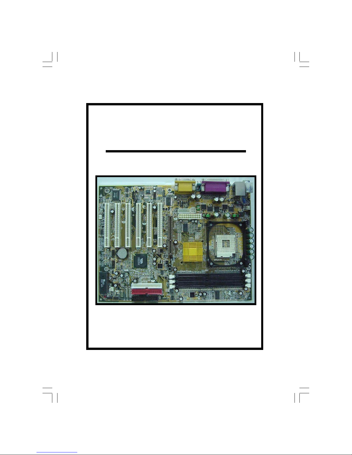
1.2.1. The P4X4-ALH Mainboard
The P4X4-ALH mainboard is a Pentium™ 4 DDR platform. Onboard it provides three DDR DIMM slots (support up to DDR333), six USB2.0 ports, six PCI
slots and one 1.5V 4X/8X AGP slot. There are also two fan connectors (for additional thermal protection) and three power supply connectors. Additionally, it
comes with Onboard Audio (AC’97 6-channel), Onboard LAN [VIA VT6103
(PHY)] and WOL (Wake-On-LAN) connector that enables it to be “woken up”
from a soft-off power state when it receives a signal from the LAN. Other onboard connectors include CD-IN, AUX-IN and Front Audio connectors etc.
1.2.2. Mainboard Dimensions
Width 305 mm
Length 230 mm
1.2.3. Environmental Limitations
Operating Temperature: 10°C to 40°C (50°F to 104°F)
Required Airflow: 50 linear feet per minute across the CPU
Storage Temperature: -40°C to 70°C (-40°F to 158°F)
Humidity: 0 to 90% non-condensing
Altitude: 0 to 10 000 feet
Introduction
1.2. Overview
1.3. Features and Specifications
Processor
The P4X4-ALH mainboard supports Intel
®
Pentium™ 4 Socket 478 CPUs.
Chipsets
Northbridge Southbridge I/O Chipset
VIA P4X400 VIA VT8235 (CD) Winbond W83697HF
PC 99 ATX External Connector
CN1: K/B
CN2: M/S
CN6: USB1
CN7: USB2
CN3: COM1
CN4: COM2
CN5: LPT
CN18: GAME
SPK-OUT / FRONT SPK-OUT
LINE-IN
MIC-IN
CN35: LAN

The P4X4-ALH Mainboard
Page 7
CPU Switching Voltage Regulator
The mainboard is equipped with a switching voltage regulator that automatically detects a DC power supply from +1.10V to +1.85V.
System Memory
The mainboard uses Double Data Rate Dual Inline Memory Modules (DDR
DIMM). Each mainboard has three 184-pin DIMM sockets which support 2.5V
(power level) single-sided or double sided PC1600 (DDR200), PC2100
(DDR266) or PC2700 (DDR333) DDR DIMM modules. The maximum memory
supported by the mainboard is 3 GB.
Expansion Slots
The mainboard is equipped with six dedicated PCI slots and one 1.5V 4X/8X
AGP slot.
Onboard Audio Features
The mainboard supports Microsoft DirectSound/DirectSound 3D and AC97 Full
Duplex.
Onboard LAN Features
The mainboard comes with Onboard LAN [VIA VT6103 (PHY)].
WOL (Wake-On-LAN) Port
The mainboard supports Wake-On-LAN functionality.
Word Size
Data Path: 8-bit, 16-bit, 32-bit, 64-bit
Address Path: 32-bit
Front Side Bus Frequency (FSB)
The Front Side Bus Frequency (FSB) clock is 400/533 MHz.
BIOS
• Award BIOS, Windows 95/98 Plug and Play (PnP) compatible
• Supports SCSI sequential boot-up
• 2 Mb flash ROM for easy BIOS upgrades
• Supports DMI2.0 function
Desktop Management Interface (DMI)
The mainboard comes with DMI 2.0 built into the BIOS. The DMI utility in the
BIOS will automatically record different information about your system
configuration and store this information in the DMI pool, which is a part of the
system board's Plug and Play BIOS. DMI, along with the appropriately
networked software, is designed for easy inventory, maintenance and the
simplified troubleshooting of computer systems.
Introduction

The P4X4-ALH Mainboard
Page 8
USB2.0 Ports
USB allows data exchange between your computer and a wide range of
simultaneously accessible external Plug and Play peripherals. The mainboard is
equipped with six USB (version 2.0) connectors. USB1 and USB2 are external
connectors. They can be found on the PC 99 ATX connector. The other USB
connectors are internal connectors and can be used to connect other USB
devices. (Cables for the internal connectors are sold separately).
Introduction
Connectors
• Two IDE connectors (support ATA 33/66/100/133)
• One Floppy Drive connector supports up to two 2.88 MB floppy drives
• One 20-pin ATX power supply connector
• One 2x2 ATX 12V power supply connector
• One 1x4 AUX12V power supply connector
• Two fan connectors
• One CD-IN connector
• One AUX-IN connector
• One WOL (Wake-On-LAN) connector
• One Front Audio connector
• One 4-Channel out connector
• One S/PDIF connector (optional)
• One IR connector (optional)
ATX Double Deck Ports (PC 99 color-coded connectors)
• Two USB2.0 ports
• Two external DB-9 serial port connectors: COM 1, COM 2 (UART)
• One SPP/ECP/EPP DB-25 parallel port
• One mini-DIN-6 PS/2 mouse port
• One mini-DIN-6 PS/2 keyboard port
• One GAME port
• One LAN port (RJ-45) connector
• Three audio jacks: SPK-OUT/FRONT SPK-OUT, LINE-IN and MIC-IN
PCI Bus Master IDE Controller
• Two PCI IDE interfaces support up to four IDE devices.
• This mainboard supports ATA 33/66/100/133 hard drives.
• PIO Mode 3 and Mode 4 Enhanced IDE (data transfer rate up to
16.6MB/sec.).
• Bus mastering reduces CPU utilization during disk transfer.
• Supports ATAPI CD-ROM, LS-120 and ZIP.
Please note that the PIN assignment of the internal USB 2.0 connectors (CN30,
CN31, CN32 and CN38) are follow the specifications of Intel standard.

The P4X4-ALH Mainboard
Page 9
Introduction
The mainboard is capable of monitoring the following health conditions of your
system:
1. Processor temperature. It has an overheat alarm.
2. VCORE/3.3V/5V/12V/-12V voltages and failure alarm.
3. Processor and chassis fan speeds. It has a failure alarm for these fans.
4. Read back capability that displays temperature, voltage and fan speed.
Hardware Monitoring System Utility
The mainboard comes with the Hardware Monitoring System utility contained
on the CD. It is capable of monitoring the system’s hardware conditions such
as the temperature of the processor, voltage, and the speed of both the CPU
and chassis fans. You are allowed to manually set a range to the items being
monitored. If the values are over or under the set range a warning message
will automatically pop up. We recommend that you use the Default Settings,
which are the ideal settings that will maintain the system in a good working
condition. To install this utility, please insert the CD into the CD-ROM drive.
The auto run screen (Driver Utility) will automatically appear. Click the Hardware Monitoring button, choose the chipset, model number and the OS that is
installed. Please refer to the CD “Readme” file for further installation instructions.
Note: Only use this utility in Windows operating systems.
1.4. System Health Monitor Functions
Dual Function Power Button
Depending on the setting in the Soft-Off By Power-Button field of the Power
Management Setup, this switch allows the system to enter the Soft-Off or
Suspend mode.
RTC Timer to Power-on the System
The RTC installed on the system board allows your system to automatically
power-on at a set date and time.
Wake-On-LAN Ready
The Wake-On-LAN function allows the network to remotely wake up a Soft
Power Down (Soft-Off) PC. Your LAN card must support the remote wakeup
function. The 5V SB power source of your power supply must be at least
720mA.
ACPI Ready
The mainboard is designed to meet the ACPI (Advanced Configuration and
Power Interface) specification. ACPI has energy saving features that support
OS Direct Power Management (OSPM) for round the clock PC operation.
1.5. System Intelligence

The P4X4-ALH Mainboard
Page 10
The following is a checklist of all the expansion slots, jumpers and connectors
that should be configured on your mainboard before you can run your PC.
Chapter 2
Chapter 2
Chapter 2
-
-
-
Hardware Installation
Hardware Installation
Hardware Installation
2.1. Installation Checklist
Installation Checklist
Expansion Slots and Sockets
CPU Socket
DIMM Slots
PCI Slots
AGP Slot
Intel® Pentium™ 4 Socket 478 CPU
Three 184-pin Slots
Six 32-bit PCI Slots
One 1.5V 4X/8X Accelerated Graphics Port Slot
Internal Connectors
CN8
CN9
CN10
CN12
CN13
CN15-A
CN15-B
CN15-D
CN16
CN17
CN21
CN30/31
CN32/38
CN36
CN39
CN45
CN46
Floppy Drive Connector
Primary IDE
Secondary IDE
Infrared
CPU Fan
ATX Power Supply
ATX 12V Power Supply
Auxiliary ATX 12V Power Supply
Wake-On-LAN Connector
Chassis Fan
CD Audio In
Universal Serial Bus 3/4
Universal Serial Bus 5/6
Sony Phillips Digital Interface
Front Audio Connector
Auxiliary In Connector
4 CH OUT
FDC
IDE1
IDE2
IR (optional)
CPU Fan
ATX
ATX12V
AUX12V
WOL
FAN2
CD-IN
USB3/4
USB5/6
S/PDIF (optional)
Front Audio
AUX-IN
4-Channel Audio Out
CN1
CN2
CN3
CN4
PS/2 Keyboard Connector
PS/2 Mouse Connector
Serial Port 1
Serial Port 2
K/B
M/S
COM1
COM2
External Connectors
“Optional”: These are manufacturing options.
Hardware Installation
The P4X4-ALH Mainboard
Page 11
You need to complete the following installation steps before you can use your
PC.
• Check and set the mainboard settings;
• Install the Central Processing Unit (CPU);
• Install the memory modules;
• Install the expansion cards;
• Connect the ribbon cables, panel wires and power supply;
• Setup the system BIOS.
2.2. Installation Steps
Hardware Installation
Installation Checklist (Continued)
CN5
CN6
CN7
CN18
CN35
Parallel Port
Universal Serial Port 1
Universal Serial Port 2
Audio/GAME Port
RJ-45 (LAN) Connector
LPT
USB1
USB2
AUDIO/GAME
LAN
Speaker and Power LED Connectors
PW
SL
HL
RS
Power On/Off and Suspend Switch Connector
Standby LED Connector
HDD LED Connector
Reset Button Connector
Speaker and Power LED Connectors
PWRLED
SPK
Power LED
Speaker Connector
JP1
JP3
JP5
JP8
JP9
K/B Power
USB1,2 Power
CPU Clock
Check 1.5V AGP (optional)
Clear CMOS
Jumpers and Switches
Before you start installing your mainboard we strongly recommend
that you use a grounded anti-static mat. We further recommend
that you attach an anti-static wristband, which is grounded at the
same location as the mat, to your wrist.
The P4X4-ALH Mainboard
Page 12
Hardware Installation
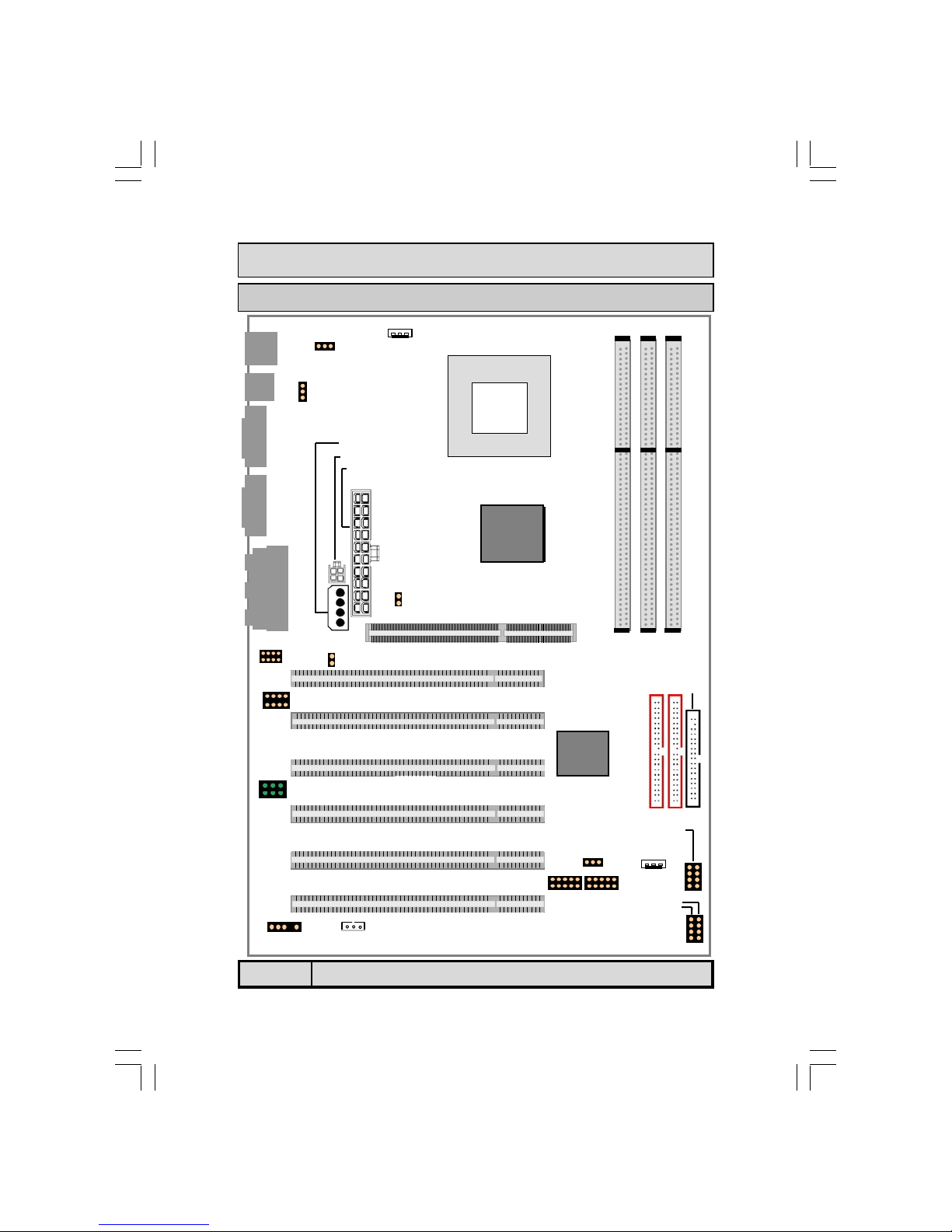
2.3. Expansion Slots, Jumpers and Internal Connectors
CPU
CN13: FAN1
DIMM1 DIMM2 DIMM3
VIA
P4X400
VIA
VT8235
JP1
JP3
CN15-D: AUX12V
CN15-B: ATX12V
CN15-A: ATX
JP5
AGP 4X/8X Slot
CN39: Front Audio
JP8
PCI 1
PCI 2
PCI 4
PCI 3
PCI 5
PCI 6
AUX-IN
CD-IN
IR
CN27: FAN2
CN16 WOL
CN38:USB6
CN32:USB5
CN31:USB4
CN30:USB3
JP9
System Panel Buttons
and LED Connectors
PWR LED
Speaker
CN10: IDE2
CN9: IDE1
CN8: FDC
1
1
1
1 1
1
1
1
1
1
1
1
1
1
6
CN46:
4 CH OUT
The P4X4-ALH Mainboard
Page 13
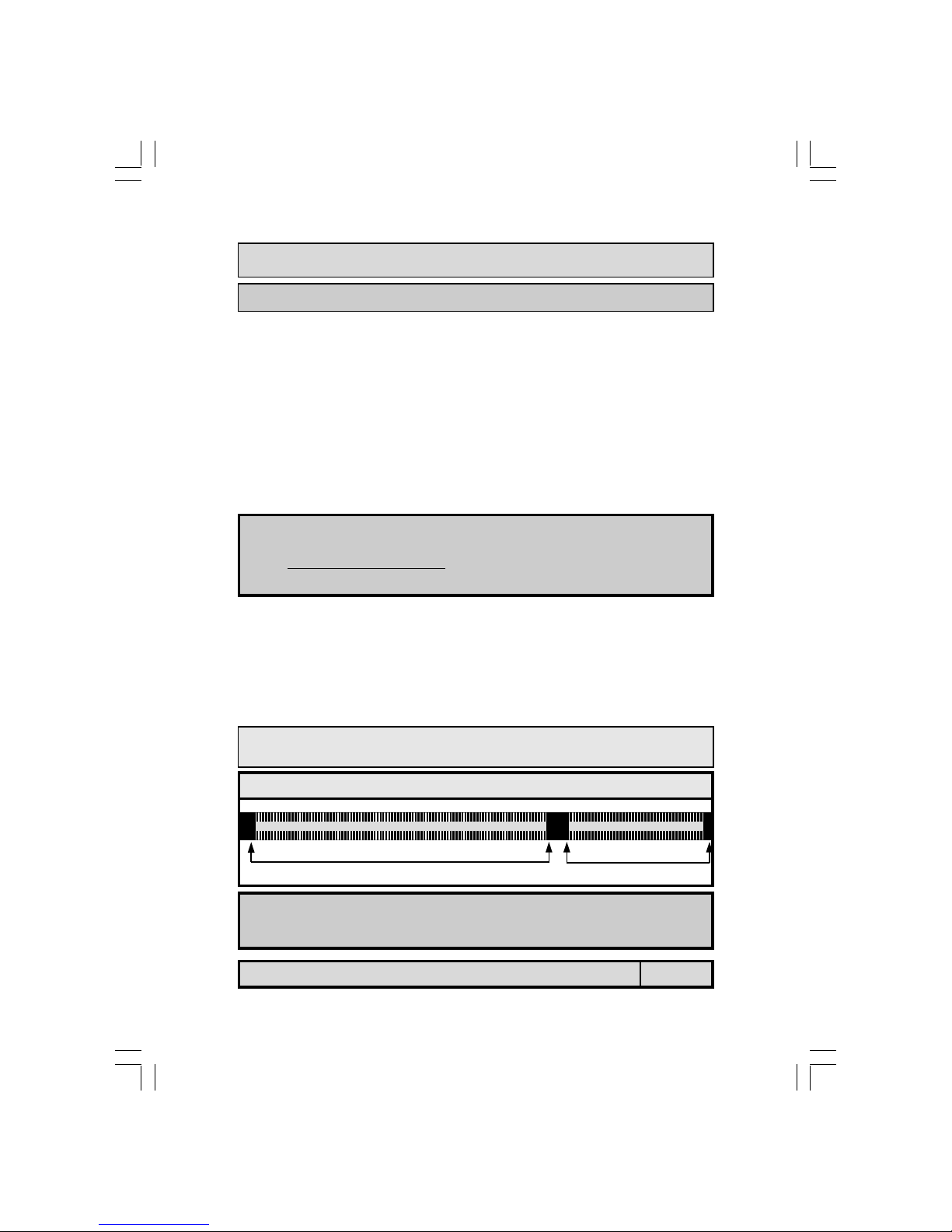
2.4.2. Memory Modules
The mainboard has three 184-pin DDR DIMM slots which are located on the
right-hand side of the board. To install the DIMM’s into these slots, make
sure the white lever at each side of the slot has been pulled down to an angle
of approximately 45°. Make sure that the DIMM is in the correct orientation.
Place the DIMM on the slot and push down firmly.The white levers will come
back up and lock the module in place.
Hardware Installation
2.4.1. Installation of the CPU
To install your processor, please complete the following set of instructions:
1. Locate a small dot marked on the top of the CPU. This mark indicates Pin
of the CPU.
2. Locate Pin 1 for the Socket on the mainboard.
3. There is a lever on the side of the socket. First push this lever sideways
and then lift it to a 90-degree angle.
4. Insert the CPU into the Socket. Please make sure that Pin 1 for the CPU is
inserted into Pin 1 of the Socket.
5. When the CPU is installed correctly push the lever back into place.
6. Install a proper heat sink with cooling fan for proper heat dissipation.
Failing to install a heat sink with cooling fan may cause overheating which
will burnout your CPU and damage your mainboard.
2.4. CPU, Memory and Expansion Slots
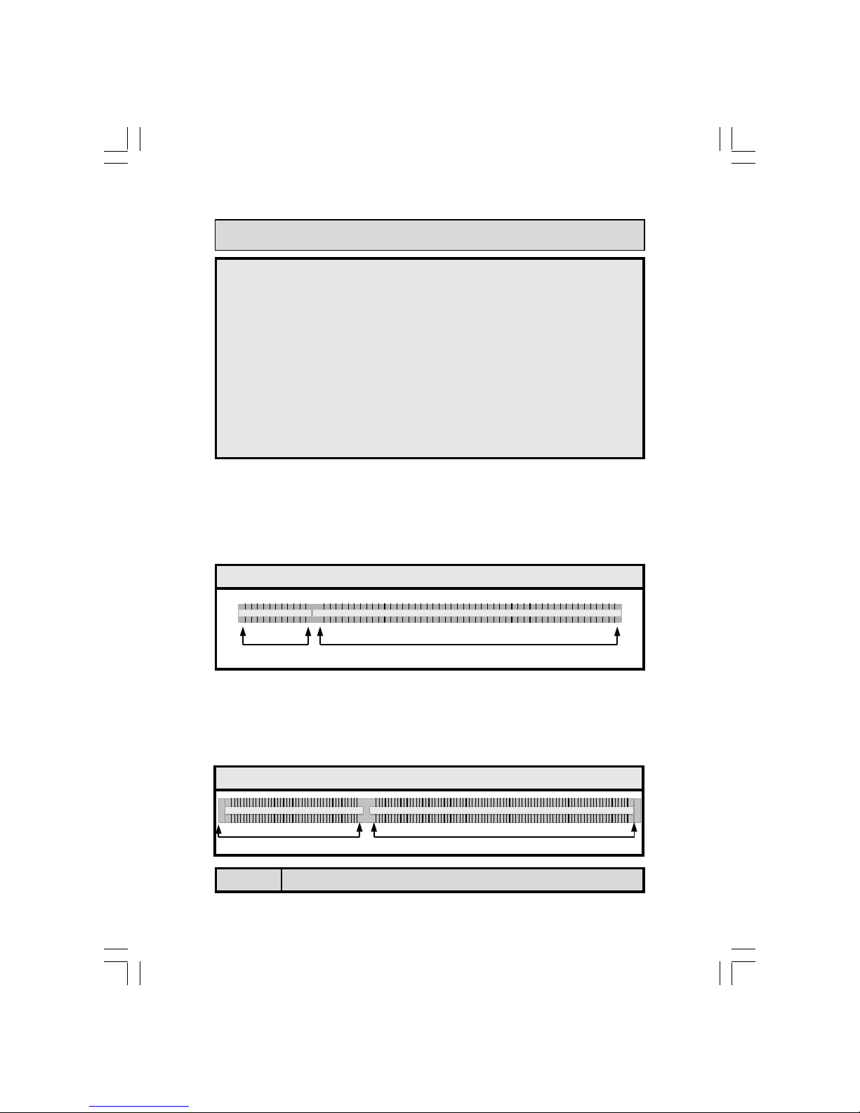
Supports 128 MB, 256 MB, 512 MB and 1 GB technologies for x8 and x16 devices.
52 pins 40 pins
Top View of a 184-pin DIMM Slot
IMPORTANT: CPU COOLING FAN
Please ensure that you have an approved heat sink with cooling fan. Without a
proper heat sink with cooling fan
you will damage both the mainboard and the
CPU.
Important: The DIMM’s can only be fitted into the slots in one orientation.
Make sure that the DIMM’s are in the correct orientation and the pins are correctly aligned before you insert them.
The P4X4-ALH Mainboard
Page 14
2.4.3. PCI Slots
The mainboard comes with six PCI slots. They are located on the left-hand
side of the board. Both PCI and PCI expansion cards may require IRQ’s. This
mainboard complies with Plug and Play (PnP) specifications. Whenever a PnP
compliant card is added the system will automatically be configured and the
IRQ’s will be assigned automatically.
Hardware Installation
NOTE: “Out Of Memory” Error Message
If you have installed more than 512 MB of RAM and are running Microsoft Windows Millennium Edition, Windows 98 Second Edition, Windows 98 or Windows 95 you may experience memory problems. Two symptoms of these problems are being unable to run
an MS-DOS session while you are running Windows or the computer may stop responding while Windows is starting.
There are three possible solutions to this problem:
1) Reduce the amount of memory Vcache uses to 512 MB or less by altering the Max-
FileCache setting in the System.ini file.
2) Use the System Configuration Utility to reduce the amount of memory Windows
uses to 512 MB or less.
3) Reduce the memory installed on your computer to 512 MB or less.
This problem can also occur if an Advanced Graphic Port (AGP) video adapter is used.
11 pins 49 pins
Top View of a 32-bit PCI Slot
2.4.4. AGP (Accelerated Graphics Port) Slot
AGP is a dedicated bus slot. It operates at 66 MHz and transfers data at a rate
up to 533 MB(8x). This allows 3D applications to run more smoothly. The
mainboard comes with a 1.5V AGP slot which is able to support 4x/8X AGP
cards.
Top View of an AGP Slot
21 pins 41 pins
 Loading...