

AZZA P4M2-BV, P4M2-BL User Manual

The AZZA P4M Mainboard Series
Cover Click Here
Table Of Contents Click Here
Introduction Click Here
Hardware Installation Click Here
BIOS Management Click Here
R
P4M Mainboard
P4M Mainboard
P4M Mainboard P4M Mainboard
Series Manual
Series Manual
Series ManualSeries Manual
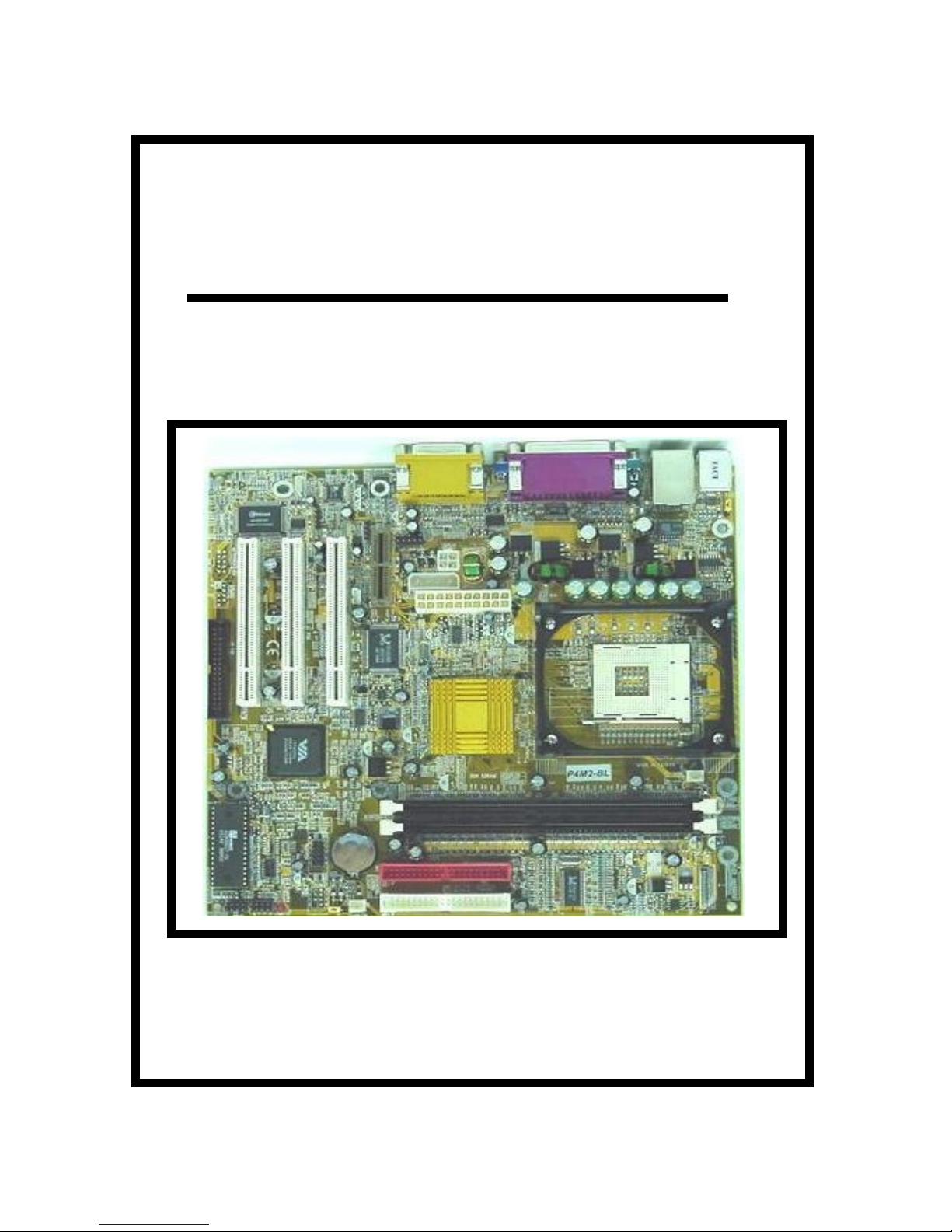
SOCKET 478 DDR M-ATX Mainboard
P4M2
P4M2----BV
P4M2P4M2
P4M2
P4M2----BL
P4M2P4M2
BV
BVBV
BL
BLBL
The AZZA P4M Mainboard Series
Version 1.x
UM-P4M2-ABVL-E1
Rev 1.0V
Creation Date: 25 January 2002
Page 1

User Notice
Copyright
This publication contains inf ormation that is protected by copyrig ht. No part of
it may be reproduced in any form or by any means or used to make any transformation adaptation witho ut prior writte n permiss ion from the copyright ho lders. This publication is provided for informational p urposes only. The manufacturer makes no r epresentations or warranties with r espect to the contents or
use of this manual and specif ically dis claims any express or implied warr anties
of merchantability or fitness for any particular purpose. The user will assume
the entire risk of the us e or the r e s ults of the use of this document. The manufacturer reserves the right to rev ise this publication and make changes to its
contents at any time, without prior notice .
2001. All Righ ts Reserved.
Trademarks
Microsoft®, MS-DOS®, Windows
istered trademarks of Microsoft Corporation. Intel® Pentium
tered trademark of Intel Corporation. Award is the registered trademark of
Award Software, Inc. Other trademarks and registered trademarks of products
appearing in this publicatio n are the properties of their respective hold er s .
TM
, Windows® 95 and Windows® 98 are reg-
TM
4 is a regis-
Package Checklist
This package contains the follo wing items:
! Mainboard
! Users manual
! One IDE cable
! One 34-pin floppy disk drive cable
! One Driver Utility CD
If any of these items are damaged or missing, please contact your dealer or
sales representative fo r assi st an ce.
Technical Support
If you require additional information or assistance during installation please
contact your dealer. Your deale r will be able to provide the latest information.
Page 2
The AZZA P4M Mainboard Series

Table of Contents
Chapter 1:- Introduction
1.1. Mainboard and PC99 External Connector Layout ...................................... 5
1.2. Overview ................................................................................................... 6
1.2.1. The P4M Mainboard Series ......................................................................6
1.2.2. The P4M Mainboard Models ....................................................................6
1.2.3. Mainboard Dimensions ............................................................................6
1.2.4. Environmental Limitations .......................................................................6
1.3. Features and Specifications ....................................................................... 6
1.4. System Health Monitor Functions .............................................................. 9
1.4.1. Hardware Monitoring System Utility .........................................................9
1.4.2. Installation .............................................................................................10
1.5. System Intelligence ................................................................................... 10
Chapter 2:- Hardware Installation
2.1. Installation Checklist ................................................................................. 11
2.2. Installation Steps ...................................................................................... 12
2.3. Expansion Slots, Jumpers and Internal Connectors .................................. 13
2.4. CPU, Memory and Expansion Slots ............................................................ 14
2.4.1. Installation of the CPU ............................................................................14
2.4.2. Memory Modules ....................................................................................14
2.4.3. PCI Slots ................................................................................................15
2.4.4. AMR (Audio Modem Riser) Slot ................................................................16
2.5. Internal Connectors ................................................................................... 16
2.5.1. Floppy Disk Drive (FDD) .........................................................................16
2.5.2. Primary and Secondary IDE Connectors ...................................................16
2.5.3. CPU and Chassis Fan Connectors .............................................................17
2.5.4. ATX Power Supply Connectors ................................................................17
2.5.5. CD Audio In and Auxiliary-In Connectors ................................................18
2.5.6. USB 3 and USB 4 Connectors ..................................................................18
2.5.7. Front Audio Connector ............................................................................19
2.6. System Panel Buttons and LED Connectors ............................................... 19
2.6.1. PW: Power On / Off and External Suspend Switch Connector ....................20
2.6.2. SL LED Connector ..................................................................................20
2.6.3. IDE HDD LED Connector .........................................................................20
2.6.4. Reset Button Connector ..........................................................................21
2.7. Speaker and Power LED Connector ........................................................... 21
2.7.1. Speaker Connector .................................................................................21
2.7.2. Front Panel Power LED ...........................................................................21
Page 5
Page 11
The AZZA P4M Mainboard Series
Page 3

Table of Contents
2.8. External Connectors .................................................................................. 21
2.8.1. PS/2 Keyboard Connector .......................................................................21
2.8.2. PS/2 Mouse Connector ............................................................................21
2.8.3. Serial Port 1 (COM 1) Connector .............................................................22
2.8.4. Parallel Port Connector ...........................................................................22
2.8.5. USB 1 and USB 2 Port Connectors ...........................................................22
2.8.6. VGA Port Connector ................................................................................22
2.8.7. Audio/Game Port Connector ....................................................................23
2.8.8. RJ-45 (LAN Port) Connector ....................................................................23
2.9. Jumper Settings ........................................................................................23
2.9.1. JP1: Keyboard Power ..............................................................................24
2.9.2. JP2: USB 1 and USB 2 Power .................................................................24
2.9.4. JP4: Clears CMOS Memory ......................................................................24
Chapter 3:- Managing The PC BIOS
3.1. Award BIOS CMOS Setup Utility ............................................................. 25
3.2. Main Menu .............................................................................................. 25
3.3. Standard CMOS Setup ............................................................................ 26
3.4. Advanced BIOS Features ........................................................................ 28
3.5. Advanced Chipset Features .................................................................... 31
3.6. Integrated Peripherals ........................................................................... 34
3.7. Power Management Setup .....................................................................38
3.8. PNP/PCI Configuration ........................................................................... 41
3.9. PC Health Status ..................................................................................... 42
3.10. Frequency/Voltage Control .................................................................... 43
3.11. Load Fail-Safe Defaults / Load Optimized Defaults ................................ 44
3.11.1. Load Fail-Safe Defaults ........................................................................44
3.11.2. Load Optimized Defaults ......................................................................44
3.12. Set Supervisor Password and User Password ......................................... 45
3.12.1. Set Supervisor Password .....................................................................45
3.12.2. Set User Password ..............................................................................45
3.13. Save & Exit Setup/Exit Without Saving .................................................. 46
3.13.1. Save & Exit Setup ................................................................................46
3.13.2. Exit Without Saving .............................................................................46
Page 25
Appendix A:- Optional Items
A.1. Standard Infrared Connector ................................................................. 47
A.2. Wake On LAN Connector ......................................................................... 47
A.3. S/PDIF Connector ................................................................................... 48
Page 4
The AZZA P4M Mainboard Series
Page 47
Introduction
Chapter 1
Chapter 1
Chapter 1
-
Introduction
-
Introduction
-
Introduction
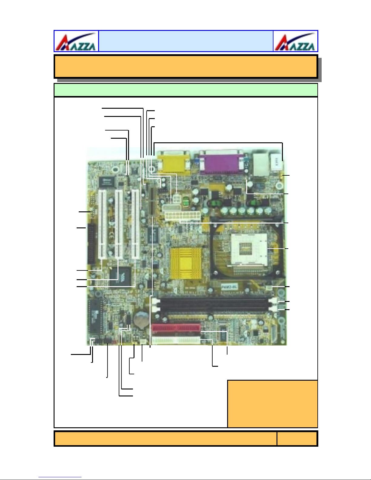
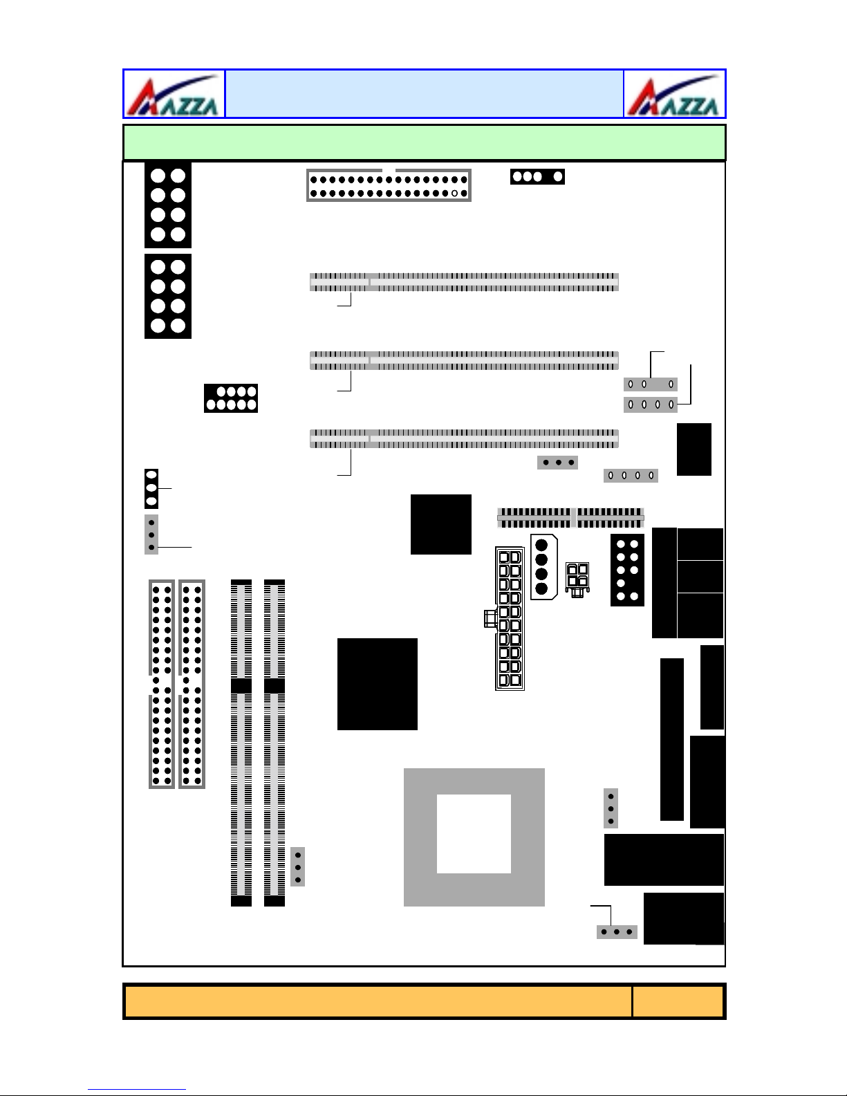
1.1. Mainboard And PC99 ATX External Connector Layout
CN21: CD-IN
CN16: WOL
CN45: AUX-IN
CN36: S/PDIF
CN12:
*
IR
CN8:
FDC
*
*
CN39: Front Audio
CN15-B: ATX12V
CN15-D: AUX12V
PC99 ATX Exte r na l Co n ne c tor
JP1:
K/B
Power
JP2:
USB
Power
PCI 3
PCI 2
PCI 1
SPK
PWR-LED
System Panel
and Power LED
Connectors
AMR Slot
CN17: CHASSIS FAN
JP4: Clear CMOS
CN31: USB4
CN30: USB3
CPU
Socket
CN13:
CPU
FAN
DIMM1
DIMM2
CN9 : IDE1
CN10: IDE2
*
The IR, WOL and S/PDIF
connectors are both
manufacturing options.
See appendix A for details
The AZZA P4M Mainboard Series
Page 5

Introduction
PC 99 ATX External Connector
CN2: PS/2 MS
CN1: PS/2 KB
1.2. Overview
1.2.1. The P4M Mainboard Series
The mainboards in the P4M2 series are Pentium™ 4 DDR platforms. They
come with two onboard DDR DIMM slots that are able to support a maximum
memory of 1GB. They also come with 3 PCI slots and 1 AMR (Audio Modem
Riser) slot. They all come with Onboard Audio (AC’97 2 channel) and they all
have Onboard VGA (Onchip PRO Savage DDR). Each P4M mainboard has and
2 fan connectors as well as CD-I N and AUX-I N connectors.
1.2.2. The P4M Mainboard Models
There are two models in this series: The P4M2-BV and the P4M2-BL. The
P4M2-BL comes with Onboard LAN (RealtekRTL8100B).
1.2.3. Mainboard Dimensions
These boards are Micro— AT X form factors. Their dimen si ons are:
Width 244 mm
Length 230 mm
1.2.4. Environmental Limitations
Operating Temperature: 10°C to 40°C (50°F to 104°F)
Required Airflow: 50 linear feet per minute across the CPU
Storage Temperature: -40°C to 70°C (-40°F to 158°F)
Humidity: 0 to 90% non-condensing
Altitude: 0 to 10 000 feet
CN35: LAN
CN7: USB2
CN6: USB1
CN5: LPT
CN3: COM
CN19: VGA
CN18: MIDI/GAME
LINE-IN
SPK-OUT
MIC-IN
1.3. Features and Specifications
Processor
The P4M mainboards support Socket 478 In te l® Pentium™ 4 CPUs.
Page 6
The AZZA P4M Mainboard Series
Introduction
Chipsets
VIA P4M266 VIA VT8233A Winbond W83697HF
CPU Switching Voltage regulator
This mainboard is equipped with a switching voltage regulator that automatically detects a DC power supply from +1.10V to +1.85V.
System Memory
The P4M mainboard s us e Doub le Data Rate Dual Inline Memory Module s (DDR
DIMM). Each mainboard has two 184-pin DIMM sockets. These sockets support
2.5V (power level) sing le-sided or double sided PC1600 (DDR200 ) or PC2100
(DDR266) DDR DIMM modules The maximum memory supported by these
mainboards is 1GB.
Expansion Slots
These mainboards are equipped with three dedicated PCI slots and one AMR
slot.
Onboard Audio Featur es
Supports Microsoft Direct Sou nd/ DirectSound 3D and AC97 Full Duplex.
Onboard LAN Features (Optional for P4M2-BV)
The P4M2-BL models come with onboard LAN which support RealtekRTL8100B.
Word Size
Northbridge Southbridge I/O Chipset
! Data Path: 8-bit, 16-bit, 32-bit, 64-bit
! Address Path: 32-bit
Front Side Bus Frequency (FSB)
The Front Side Bus Fr equency (FSB) for both models is 400MHz.
BIOS
! Award BIOS, Windows 95/98 Plug and Play (PnP) compatible.
! Supports SCSI sequential boot-up.
! Flash EPROM for easy BIOS upgrades.
! Supports DMI 2.0 function
The AZZA P4M Mainboard Series
Page 7

Introduction
Desktop Management Interface (DMI)
The mainboard comes with DMI 2.0 built into the BIOS. The DMI utility in the
BIOS will automatically record different information about your system
configuration and store this information in the DMI pool, which is a part of the
system board's Plug and Play BIOS. DMI, along with the appropriately
networked software, is designed for easy inventory, maintenance and the
simplified troubleshooting of computer systems.
WOL (Wake-On-LAN) Port (optional see Appendix A)
One WOL connector supports Wake-On-LAN functionality.
USB Ports
USB allows data exchange between your computer and a wide range of
simultaneously accessible external Plug and Play peripherals. These models
are equipped with four (version 1.1) USB connectors. USB 1 and USB 2 are
external connector s. They can be found on the PC 99 ATX connector. The other
USB connectors are internal connectors and can be used to connect other USB
devices. (Cables for the internal connectors are sold separately).
Connectors
! Two IDE connectors.
! One floppy drive interface supports up to two 2.88MB floppy drives.
! One 20-pin ATX power supply connector.
! One 2x2 ATX 12 V power supply connector.
! One 1x4 AUX12 V power supply co nnector.
! Two fan connect ors.
! One CD audio-IN connector.
! One Aux-IN connector
! One WOL (Wake-On-Lan Connector) (optional)
! One S/PDIF connector (optional)
! One IR connector (optional)
ATX Double Deck Ports (PC 99 color-coded connectors)
! Two USB ports.
! One external DB-9 serial port connector: COM 1(UART).
! One VGA Port
! One SPP/ECP/EPP DB-25 parallel port.
! One mini-DIN-6 PS/2 mouse port.
! One mini-DIN-6 PS/2 ke yb oard port.
! One game/MIDI port.
! On LAN Port (RJ-45) conne c tor (o nly for the P4M2-BL)
! Three audio jacks: speak-out, line-in and mic-in.
Page 8
The AZZA P4M Mainboard Series
Introduction
PCI Bus Master IDE Controller
! Two PCI IDE interfaces support up to four IDE devices.
! P4M2 mainboards support ATA/33, ATA/66, ATA/100 and ATA/133
hard drives.
! PIO Mode 3 and Mode 4 Enhanced IDE (data transfer rate up to
16.6MB/sec.).
! Bus mastering reduces CPU utilization during disk transfer.
! Supports ATAPI CD-ROM, LS-120 and ZIP.
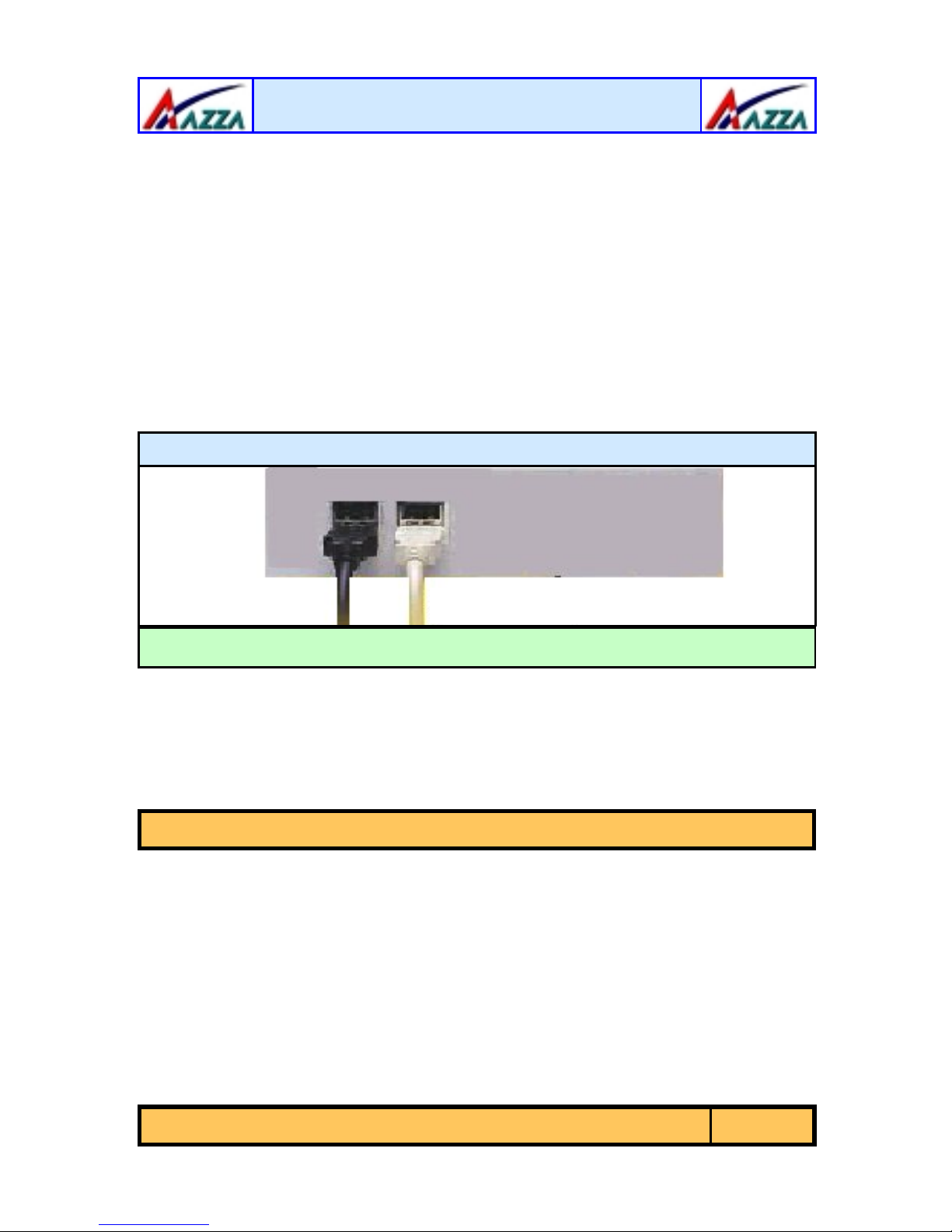
Utility Panel: Front USB
The Front Utility Panel is a unique desig n concept that brings USB ports to the
front of your system. The inter nal U SB co nne c tors can be connected to these
ports. The Front Utility Pane l is show n be low .
Front Utility Panel
Front USB Ports
1.4. System Health Monitor Functions
The mainboard is capable of monitoring the following health conditions of your
system:
1. Processor temperature. It has an overheat alarm.
2. VCORE/3.3V/5V/12V/-12V voltages and failure alarm.
3. Processor and chassis fan speeds. It has a failure alarm for these fans.
4. Read back capability that display s te mperature, voltage and fan speed.
Note:
1.4.1. Hardware Monitoring System Utility
The mainboards both come with the Hardware Monitoring System utility
contained on the CD. It is capable of monitoring the system’s hardware
conditions such as the temperature of the proc essor , voltage, and the spe ed of
both the CPU and chassis fans. You are allowed to manually set a range to the
items being monitored. If the values are over or under the set range a warning
message will automatically pop up. We recommend that you use the Default
Settings, which are the ideal settings that will maintain the system in a good
working condition.
Only use this utility in Windows ® 95 or Windows ® 98 operating systems.
The AZZA P4M Mainboard Series
Page 9
Introduction
1.4.2. Installation
To install this utility, pleas e insert the CD into the CD-ROM drive. The auto run
screen (Driver Utility) w ill automatically appear. Click the Hard w are Mo nito ring
button, choose the chipset, mod e l number and the OS that is installe d . Ple a s e
refer to the CD “Readme” f ile for fur ther installation instructions.
1.5. System Intelligence
Dual Function Power Button
Depending on the setting in the Soft-Off By Power-Button field of the Power
Management Setup, this switch allows the system to enter the Soft-Off or
Suspend mode.
External Modem Ring-on (Optional)
The Modem Ring-on feature allows the system that is in the Suspen d mode or Soft Power
Off mode to wake-up/power-on to respond to incoming calls. This feature supports the
external modem only.
RTC Timer to Power-on the System
The RTC installed on the system board allows your system to automatically
power-on at a set date and time.
Wake-On-LAN Ready
The Wake-On-LAN function allows the network to remotely wake up a Soft
Power Down (Soft-Off) PC. Your LAN card must support the remote wakeup
function. The 5V SB power source of your power supply must be at least
720mA.
ACPI Ready
The mainboard is designed to meet the ACPI (Advanced Configuration and
Power Interface) specification. ACPI has energy saving features that support
OS Direct Power Management (OSPM) for ro und the clo ck PC oper ation.
Page 10
The AZZA P4M Mainboard Series
Hardware Installation
Chapter 2
Chapter 2
Chapter 2
2.1. Installation Checklist
The following is a checklist of all the exp ansion slots, jumpers and connectors
that should be configured on your mainbo ard before you can run your pc.
Expansion Slots and Sockets
CPU Socket
DIMM Slots
PCI Slots
CN8
CN9
CN10
CN12
CN13
CN15-A
CN15-B
CN15-D
CN16
CN17
CN21
CN30
CN31
CN38
CN39
CN45
Socket 478 Intel® Pentium™ 4 CPUs.
Two 184 pin slots that supports up to 1GB of DDR SDRAM .
Three 32 bit PCI Slots.
Floppy Disk Drive
Primary IDE
Secondary IDE
Infrared
CPU Fan
ATX Power Supply
ATX 12V Power Supply
Auxiliary ATX 12V Power Sup ply
Wake On Lan
Chassis Fan
CD Audio In
Universal Serial Bus 3
Universal Serial Bus 4
Sony Phillips Digital I nte rface
Front Audio
Auxiliary In
-
Hardware Installation
-
Hardware Installation
-
Hardware Installation
Installation Checklist
Internal Connectors
FDC
IDE1
IDE2
IR (optional
CPU Fan
ATX
ATX12V
AUX12V
WOL (optional
FAN2
CD-In
USB3
USB4
S/PDIF (optional
Front Audio Connector
Aux-IN
*
*
*
)
)
)
CN1
CN2
CN3
(optional*): These are manufacturing options. Please see Appedix A for
more details.
PS/2 Keyboard Conne c tor
PS/2 Mouse Connector
Serial Port 1
The AZZA P4M Mainboard Series
External Connector s
PS/2 KB
PS/2 MS
COM1
Page 11

Hardware Installation
Insta llation Checklist (Continued)
CN5
CN6
CN7
CN18
CN19
CN35
PW
SL
HL
RS
PWR-LED
SPK
JP1
JP2
JP4
Parallel Port
Universal Serial Port 1
Universal Serial Port 2
Game/Audio Port
VGA Port
RJ-45 (LAN) Connec tor
LPT
USB1
USB2
Audio/Game
VGA
LAN (only for P4M2-BL)
Speaker and Power LED Connector
Power On/Off and Su spend Switch Connector.
Standby LED Connector
HDD LED Connector
Reset Button Connec tor
Speaker and Power LED Connector
Power LED
Speaker Connector
Jumpers and Switches
K/B Power
USB Power
Clear CMOS
2.2. Installation Steps
You need to complete the following ins tallatio n steps before you can use your
PC.
! Check and Set the Mainboard Settings.
! Install the Central Processing Unit (CPU).
! Install the Memory Modules.
! Install the Expansion Cards.
! Connect the Ribbon Cables, Panel Wires and the Power Supply.
! Setup the syste m BI OS
Before you start
installing your mainboard we strongly recommend
that you use a grounded anti-static mat. We further recommend
that you attach an anti-static wrist band, which is grounded at the
same location as the mat, to your wrist.
Page 12
The AZZA P4M Mainboard Series
Hardware Installation
2.3. Expansion Slots, Jumpers and Internal Connectors
1 PWRLED
1 PWRLED
PW SL HL RS
PW SL HL RS
1
1
1
1
1 SPKR
1 SPKR
1111
1111
10
10
JP4: Clear CMOS
JP4: Clear CMOS
CN17: Ch assis Fan
CN17: Ch assis Fan
CN30: USB 3
CN30: USB 3
CN31: USB4
CN31: USB4
DIMM 2
DIMM 2
CN8: FDC
CN8: FDC
1
DIMM 1
DIMM 1
1
PCI 1PCI 2PCI 3
PCI 1PCI 2PCI 3
Chip
Chip
LAN
LAN
1
1
CN12: IR
CN12: IR
1
1
CN16:
WOL
CN16:
WOL
AMR Slot 1
AMR Slot 1
1
11
1
1
1
1
1
1
CN45: AUX-IN
CN45: AUX-IN
1CN36: S/PD IF 1
1CN36: S/PD IF 1
AC’97
AC’97AC’97
CN21: CD-IN
CN21: CD-IN
Mic Line SPK
-IN -IN -O UT
Mic Line SPK
-IN -IN -O UT
CN18: GAME
CN18: GAME
1
1
1
1
1
1
CN 10: IDE2
CN 10: IDE2
CN 10: IDE2
CN 9: IDE1
CN 9: IDE1
CN 9: IDE1
CN 9:
IDE 1
CN 9:
IDE 1
CN 9:
1
1
CN13: CPU Fan
CN13: CPU Fan
IDE 1
P4M266
P4M266
P4M266
CN15-A: ATX
CN15-A: ATX
CPU
CPU
1
1
CN15-D: AUX12V
CN15-D: AUX12V
CN15-B: ATX12V
1
CN15-B: ATX12V
1
CN39: Front Au dio
CN39: Front Au dio
CN19: VG A CN3: COM1 CN1:
CN19: VG A CN3: COM1 CN1:
CN5: LP T
CN5: LP T
JP2: USB Power
JP2: USB Power
1
1
CN35
CN35
USB2
JP1: KB P ower
JP1: KB P ower
USB2
LAN
LAN
MS
MS
1
1
CN6:
CN7:
CN6:
CN7:
USB1
USB1
CN2:
CN2:
KB
KB
The AZZA P4M Mainboard Series
Page 13
Hardware Installation
2.4. CPU, Memory and Expansion Slots
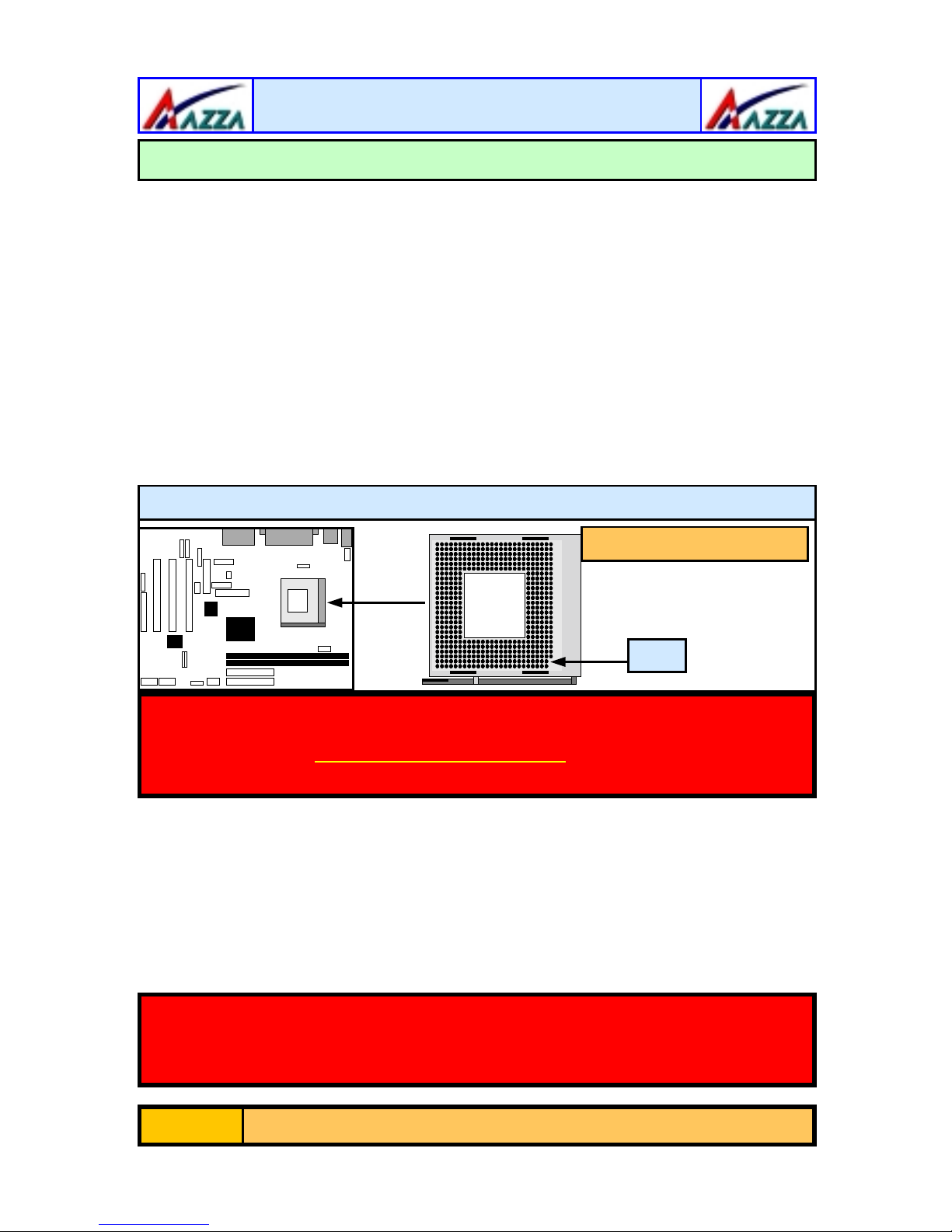
2.4.1. Installation of the CPU
To install your processor, please complete the following set of instructions
1. Locate a small dot marked on the to p of the CPU. This mark indicate s
Pin 1 of the CPU.
2. Locate Pin 1 for the Socket on the mainboard.
3. There is a lever on the side of the socket. First push this lever sideways and then lift it to a 90-degree angle.
4. Insert the CPU into the Socket. Please make sure that Pin 1 for the
CPU is inserted into Pin 1 of the Socke t.
5. When the CPU is installed correctly push the lev er bac k into place .
6. Install a proper heat sink with cooling fan for prope r heat dissi-
pation. Failing to ins tall a heat sink with coo ling fan may cause overheating which will burnout your CPU and damage your mainboard.
CPU Socket 478
Supports PentiumTM 4
mPGA478BmPGA478BmPGA478B
Pin 1
IMPORTANT: CPU COOLING FAN
Please ensure that you have an approved heat sink with cooling fan.
Without a p rop er heat s ink with cooling fan
mainboard and the CPU.
2.4.2. Memory Modules
The P4M mainboards have two 184-pin DDR DIMM slots and are able to
support a maximum of 1GB of DDR200/266 memory. The DDR DIMM slots
are located on the right hand side of the board. To install the DIMM’s into
these slots, make sure the white lever at each side of the slot has been pulled
down to an angle of approximately 45°. Make sure that the DIMM is in the
correct orientatio n. Plac e the DI MM o n the s lo t and push down firmly.The white
levers will come back up and lock the module in place.
Important: The DIMM’s can only be fitted into the slots in one orientation. Make sure that the DIMM’s are in the correct orientation and
the pins are correctly ali gned before you insert them.
you will damage both the
Page 14
The AZZA P4M Mainboard Series
 Loading...