

AZZA KT133TX, KT3ABX, KT133BX, KT133BL, KT3ABL User Manual
...
V
V
V
I
I
I
A
A
A
K
K
K
T
T
T
1
1
1
3
3
3
3
3
3
a
a
a
n
n
n
d
d
d
K
K
K
T
T
T
1
1
1
3
3
3
3
3
3
A
A
A AA
A
T
T
T
X
X
X
C
C
C
h
h
h
i
i
i
p
p
p
s
s
s
e
e
e
t
t
t
s
s
s
F
F
F
o
o
o
r
r
r
A
A
A
M
M
M
D
D
D
D
D
D
u
u
u
r
r
r
o
o
o
n
n
n
T M
a
a
a
n
n
n
d
d
d
A
A
A
t
t
t
h
h
h
l
l
l
o
o
o
n
n
n
T M
p
p
p
r
r
r
o
o
o
c
c
c
e
e
e
s
s
s
s
s
s
o
o
o
r
r
r
S
S
S
u
u
u
p
p
p
p
p
p
o
o
o
r
r
r
t
t
t
i
i
i
n
n
n
g
g
g
M
M
M
o
o
o
d
d
d
e
e
e
l
l
l
K
K
K
T
T
T
1
1
1
3
3
3
3
3
3
T
T
TXX
X
K
K
K
T
T
T
1
1
1
3
3
3
3
3
3
B
B
B
X
X
X
K
K
K
T
T
T
1
1
1
3
3
3
3
3
3
B
B
B
L
L
L
K
K
K
T
T
T
3
3
3
A
A
A
B
B
B
X
X
X
K
K
K
T
T
T
3
3
3
A
A
A
B
B
B
L
L
L
K
K
K
T
T
T
3
3
3
E
E
E
B
B
B
X
X
X
Doc number: UM-KT133TX-E2…………………………………………………………………..PRINTED IN TAIWAN

U
U
U
s
s
s
e
e
e
r
r
r
’
’
’
s
s
s
N
N
N
o
o
o
t
t
t
i
i
i
c
c
c
e
e
e
C
C
C
o
o
o
p
p
p
y
y
y
r
r
r
i
i
i
g
g
g
h
h
h
t
t
t
This publication contains information that is protected by copyright. No part of it may be
reproduced in any form or by any means or used to make any transformation adaptation
without prior written permission from the copyright holders. This publication is provided
for informational purposes only. The manufacturer makes no representations or warranties
with respect to the contents or use of this manual and specifically disclaims any express or
implied warranties of merchantability or fitness for any particular purpose. The user will
assume the entire risk of the use or the results of the use of this document. The
manufacturer reserves the right to revise this publication and make changes to its
contents at any time, without prior notice.
2000. All Rights Reserved.
T
T
T
r
r
r
a
a
a
d
d
d
e
e
e
m
m
m
a
a
a
r
r
r
k
k
k
s
s
s
Microsoft ® MS-DOS ®, Windows TM, Windows ® 95 and Windows ® 98 are registered
trademarks of Microsoft Corporation. AMD Duron TM and AMD Athlon TM are registered
trademarks of AMD Corporation. Award is a registered trademark of Award Software, Inc.
Other trademarks and registered trademarks of products appearing in this publication are
the properties of their respective holders.
P
P
P
a
a
a
c
c
c
k
k
k
a
a
a
g
g
g
e
e
e
C
C
C
h
h
h
e
e
e
c
c
c
k
k
k
l
l
l
i
i
i
s
s
s
t
t
t
This package contains the following items:
n Mainboard
n Users manual
n One IDE cable for ATA/33, ATA/66 or ATA100IDE drives
n One 34-pin floppy disk drive cable
n One Driver Utility CD
If any of these items are missing or damaged, please contact your dealer or sales
representative for assistance.
T
T
T
e
e
e
c
c
c
h
h
h
n
n
n
i
i
i
c
c
c
a
a
a
l
l
l
S
S
S
u
u
u
p
p
p
p
p
p
o
o
o
r
r
r
t
t
t
If you require additional information, assistance during installation, please contact your
dealer. Your dealer will be able to provide the latest information. If you need additional
help, please visit our web site for technical support.

I
I
I
TTaabbllee ooff CCoonntteenntts
s
CChhaapptteerr 11 –– IInnttrroodduuccttiioon
n
Section Sub-section Page
1.1 Mainboard Layout……………………………………………………. 1-1
1.1.1 Mainboard Dimension………………………………………….…… 1-1
1.1.2 Environment Limitation……………………………………..……… 1-2
1.2 ATX Form Factor……………………………………………………… 1-2
1.3 Features and Specifications………………………………………. 1-2
1.4 System Health Monitoring Function…………………………… 1-2
1.4.1 Hardware Monitoring System Utility…………………………… 1-4
1.4.2 Installation of HMSU………………………………………………… 1-5
1.5 Intelligence…………………………………………………………….. 1-5
Chapter 2 - Hardware Installation
Section Sub-section Page
2.1 Mainboard Setting………………………………………………. 2-1
2.2 Installation of Processor………………………………………. 2-2
2.3 Installation of DIMM Memory……………………………….. 2-3
2.4 Internal Connectors…………………………………………….. 2-3
2.4.1 PCI Slot/ISA Slot…………………………………………………. 2-3
2.4.2 AMR Slot……………………………………………………………. 2-4
2.4.3 Floppy Disk Drive Connectors………………………………. 2-4
2.4.4 Primary and Secondary IDE Connectors………………… 2-4
2.4.5 Standard Infrared (SIR) Connector……………………….. 2-5
2.4.6 Cooling and Chassis Fan Power Connectors……………… 2-5
2.4.7 ATX Power Connector…………………………………………. 2-6
2.4.8 WOL (Wake on LAN) Connector……………………………. 2-6
2.4.9 CD Audio-in Connector………………………………………… 2-7
2.4.10 USB (Universal Serial Bus)………………………………….. 2-7
2.4.11 System Panel Buttons and LED Connectors……………. 2-8
2.4.12 Speaker and Power LED………………………………………. 2-9
2.5 External Connector…………………………………………….. 2-9
2.5.1 PS/2 Mouse and Keyboard Connectors…………………. 2-10
2.5.2 Serial Port Com 1 and 2 Connectors…………………….. 2-10
2.5.3 Parallel Port Connector……………………………………….. 2-10
2.5.4 USB (Universal Serial Bus) Port 1 and 2………………… 2-10
2.5.5 Audio/Game Port Connectors……………………………….. 2-11

III
I
T
T
T
a
a
a
b
b
b
l
l
l
e
e
e
o
o
o
f
f
f
C
C
C
o
o
o
n
n
n
t
t
t
e
e
e
n
n
n
t
t
t
s
s
s
CChhaapptteerr 33 –– MMaannaaggiinngg YYoouurr PPCC BBIIOOS
S
Section Sub-section Page
3.1 AWARD BIOC CMOS Setup Utility…………………………. 4-1
3.2 Main Menu…………………………………………………………. 4-1
3.3 Standard CMOS Setup…………………………………………. 4-3
3.4 Advanced BIOS Features……………………………………… 4-5
3.5 Advanced Chipset Features………………………………….. 4-9
3.6 Integrated Peripherals…………………………………………. 4-13
3.7 Power Management…………………………………………….. 4-16
3.8 PnP/PCI Configuration…………………………………………. 4-20
3.9 PC Health Status…………………………………………………. 4-22
3.10 Frequency/Voltage Control………………………………….. 4-23
3.11 Load Optimized Default……………………………………….. 4-24
3.12 Set Supervisor Password……………………………………… 4-25
3.13 Set User Password……………………………………………… 4-26
3.14 Save and Exit Setup…………………………………………… 4-27

IIIII
I
I
I
I
n
n
n
t
t
t
r
r
r
o
o
o
d
d
d
u
u
u
c
c
c
t
t
t
i
i
i
o
o
o
n
n
n
CChhaapptteerr 11 –– IInnttrroodduuccttiioon
n
11..11
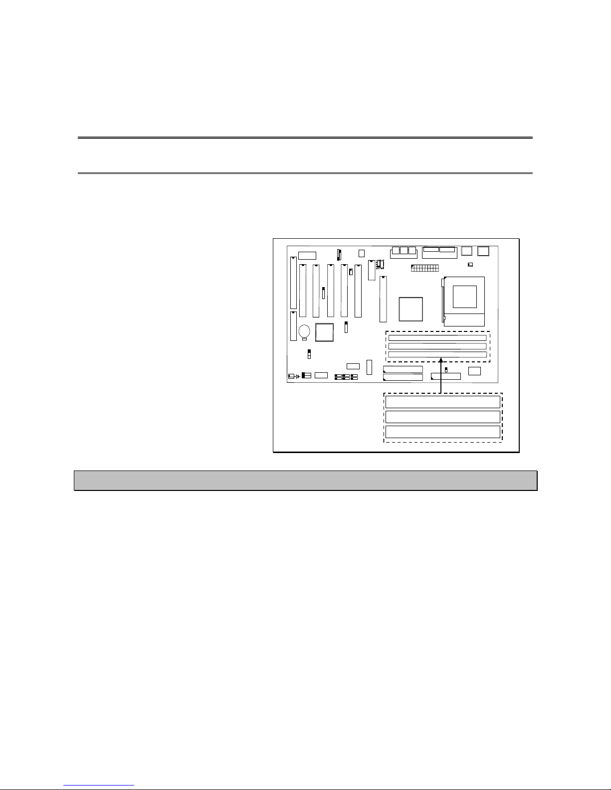
MMAAIINNBBOOAARRDD LLAAYYOOUUT
T
U
S
B
D
I
M
M
3
A
G
P
S
L
O
T
CPU
C
N
9
I
D
E
1
C
N
1
0
I
D
E
2
D
I
M
M
2
D
I
M
M
1
BAT1
123
C
N
8
F
D
C
4
B
A
C
JP1
P
C
I
S
L
O
T
CN17
CN12
IR
CD-IN
Panel
Button
Chassis
Fan
A
M
R
CPU
Fan
ATX-Po wer
Connector
A= COM1
B=COM2
C=LPT
CN16
WOL
1= SPK-OUT
2=LINE-IN
3=MIC-IN
4=MIDI/GAME
USB3
USB4
SPK
PWR-LED
JP8
Mou se
K/B
USB1
USB2
Sleep
LED
P
C
I
S
L
O
T
P
C
I
S
L
O
T
P
C
I
S
L
O
T
P
C
I
S
L
O
T
CN34
Note! Audio port (CN18) and AMR slot are only available in KT133TX, KT133BX
KT3EBX and KT3ABX models only.
11..11..11 MMaaiinnbbooaarrdd DDiimmeennssiioon
n
n Width & Length: 305 mm x 210 mm.
n Height: 1 1/2 inches
n PCB Thickness: 4 layers, 0.05 inches.
n Weight: 18 ounces.
11..11..22 EEnnvviirroonnmmeenntt LLiimmiittaattiioon
n
n Operating Temperature: 10 to 40 . (50 to 104)
n Required Airflow: 50 linear feet per minute across CPU.
n Storage Temperature: - 40 to 70. (- 40 to 158)
n Humidity: 0 to 90% non-condensing.
n Altitude: 0 to 10,000 feet
11--1
1
I
I
I
n
n
n
t
t
t
r
r
r
o
o
o
d
d
d
u
u
u
c
c
c
t
t
t
i
i
i
o
o
o
n
n
n
11..22
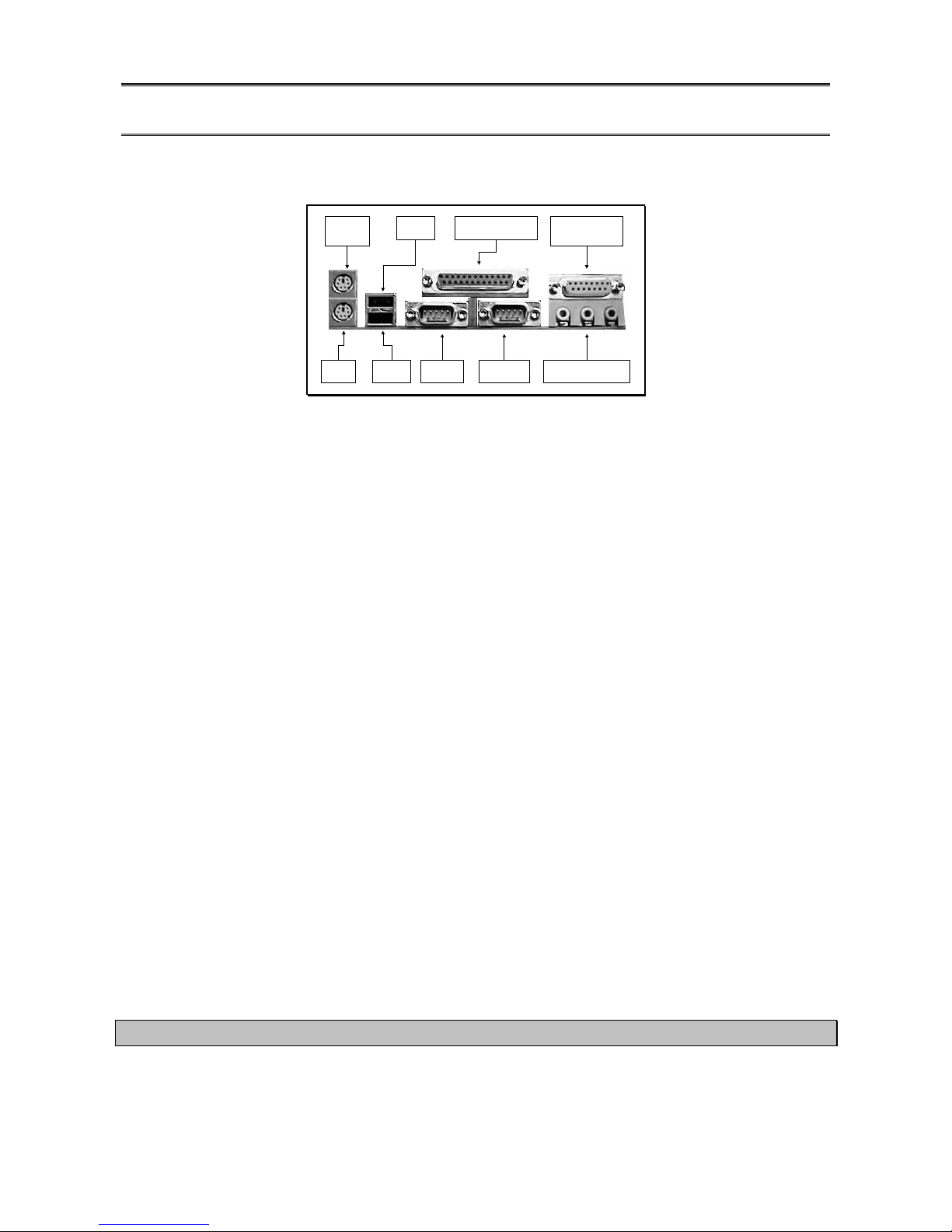
AATTXX FFoorrmm FFaaccttoorr CCoonnnneeccttoor
r
PS/2
Mouse
USB2
USB1
COM1 Audio Port
Parallel Port
K/B
Game/MIDI
Port
COM 2
11..33
FFeeaattuurreess aanndd SSppeecciiffiiccaattiioonns
s
PPrroocceessssoor
r
n Support AMD DuronTM and AthlonTM Socket A processors.
CChhiippsseet
t
n VIA ® VT8363/VT82C686A enhanced AGPset (PC-133) for KT133TX.
n VIA ® VT8363/VT82C686B enhanced AGPset (PC-133) for KT133BX and KT133BL.
n VIA® VT8363E/VT82C686B enhanced AGPset (PC-133) for KT3EBX.
n VIA ® VT8363A/VT82C686B enhanced AGPset (PC-133) for KT3ATX and KT3ABL.
CCPPUU SSwwiittcchhiinngg VVoollttaaggee RReegguullaattoor
r
n Equipped with a switching voltage regulator that automatically detects +1.10V to1.8V
DC power supply.
SSyysstteemm MMeemmoorry
y
n 32MB to1.5GB memory using VCM (Virtual Channel Memor y) SDRAM.
n Three 168-pin DIMM sockets.
n Uses x64 PC SDRAM, 3.3V.
n Support PC-100 SDRAM DIMM and PC-133 SDRAM DIMM.
EExxppaannssiioonn SSllootts
s
n The mainboard is equipped with 1 dedicated AGP slot (support 1x, 2x and 4x AGP
graphic card), 4 dedicated PCI slots, 1-sharedPCI/ISA slot and 1 AMR (Audio/Modem
Riser) slot. AMR is an interface designed for installing audio riser card, modem riser
card or audio/modem riser card that is compliant to the AMR specification.
Note: For KT133BL and KT3ABL, the mianboard have no AMR slot onboard.

11--2
2
I
I
I
n
n
n
t
t
t
r
r
r
o
o
o
d
d
d
u
u
u
c
c
c
t
t
t
i
i
i
o
o
o
n
n
n
OOnnbbooaarrdd AAuuddiioo FFeeaattuurrees
s
n Supports Microsoft ® DirectSound/DirectSound 3D.
n AC97 supported full duplex, independent sample rate converter for audio recording
and playback.
Note: KT133BL and KT3ABL do not have the 3D audio interface onboard
WWoorrdd SSiizze
e
n Data Path: 8-bit, 16-bit, 32-bit, 64-bit.
n Address Path: 32-bit.
FFRROONNTT SSIIDDEE BBUUSS FFRREEQQUUEENNCCY
Y
n KT133TX, KT133BX, KT133BL and KT3EBX support 200MHz. [100MHz DDR (Double
Data Rate)] FSB.
n KT3ABX and KT3ABL support 200 and 266MHz. [133MHz DDR (Double Data Rate)]
FSB.
BBIIOOS
S
n Award BIOS, Windows ® 95/98 Plug and Play compatible.
n Supports SCSI sequential boot-up.
n Flash EPROM for easy BIOS upgrades (2Mbit).
n Supports DMI 2.0 function.
DDeesskkttoopp MMaannaaggeemmeenntt IInntteerrffaaccee ((DDMMII)
)
n The mainboard comes with a DMI 2.0 built into the BIOS. The DMI utility in the BIOS
will automatically records various information about your system configuration and
store these information in the DMI pool, which is a part of the system board's Plug
and Play BIOS. DMI, along with the appropriately networked software, is designed for
easy inventory, maintenance and simplify troubleshooting of computer systems.
WWOOLL ((WWaakkee--OOnn--LLaann)) PPoorrt
t
n One WOL connector supports Wake-On-LAN functionality.
UUSSBB PPoorrtts
s
n The mainboard is equipped with 4 USB ports. USB allows data exchange between
your computer and a wide range of simultaneously accessible external Plug and Play
peripherals. (Optional cable for two connectors is sold separately).
CCoonnnneeccttoorrs
s
n One connector for IrDA interface.
n Two IDE connectors.
n One floppy drive interface supports up to two 2.88MB floppy drives.
n One 20-pin ATX power supply connector.
n CPU, chassis and AGP fan connectors.
n Three CD audio-in connectors.
n One TAD connector for telephony audio devices.

11--3
3
I
I
I
n
n
n
t
t
t
r
r
r
o
o
o
d
d
d
u
u
u
c
c
c
t
t
t
i
i
i
o
o
o
n
n
n
AATTXX DDoouubbllee DDeecckk PPoorrttss ((PPCC 9999 ccoolloorr--ccooddeedd ccoonnnneeccttoorrss)
)
n Two USB ports.
n Two NS16C550A-compatible DB-9 serial ports (URATs).
n One SPP/ECP/EPP DB-25 parallel port.
n One mini-DIN-6 PS/2 mouse port.
n One mini-DIN-6 PS/2 keyboard port.
n One game/MIDI port.
n Three audio jacks: line-out, line-in and mic-in.
PPCCII BBuuss MMaasstteerr IIDDEE CCoonnttrroolllleer
r
n Two PCI IDE interfaces support up to four IDE devices.
n Supports ATA/33 and ATA/66 hard drives for KT133TX.
n Support ATA/33, ATA/66 and ATA100 hard drives for KT133BX, KT133BL, KT3EBX,
KT3ABX and KT3ABL.
n PIO Mode 3 and Mode 4 Enhanced IDE (data transfer rate up to 16.6MB/sec.).
n Bus mastering reduces CPU utilization during disk transfer.
n Supports ATAPI CD-ROM, LS-120 and ZIP
IIrrDDAA IInntteerrffaacce
e
n The mainboard is equipped with an IrDA connector for wireless connectivity between
your computer and peripheral devices. It supports peripheral devices that meet the
HPSIR or ASKIR standard.
11..44
SSyysstteemm HHeeaalltthh MMoonniittoorr FFuunnccttiioonns
s
n The mainboard is capable of monitoring the following system health conditions: -
1. Monitors processor/system temperature and overheat alarm.
2. Monitors VCORE/3.3V/5V/12V/2.5V voltages and failure alarm.
3. Monitors processor/chassis fan speed and failure alarm.
4. Automatic fan on/off control.
5. Read back capability that displays temperature, voltage and fan speed.
11..44..11HHaarrddwwaarree MMoonniittoorriinngg SSyysstteemm UUttiilliitty
y
n The mainboard comes with the Hardware Monitoring System utility contained in the
provided CD (CD Driver). It is capable of monitoring the system’s hardware conditions
such as the temperature of the processor and system, voltage, and speed of the CPU
and chassis fans. You are allowed to manually set a range to the items being
monitored. If the values are over or under the set range, a warning message wills
pop-up. The utility can also be configured to allow a beeping alarm to sound
whenever an error occurs. We recommend that you use the Default Setting, which is
the ideal setting that would maintain the system in good working condition.

Note: Use this utility only in Windows ® 95 or Windows ® 98 operating system.
11--4
4
I
I
I
n
n
n
t
t
t
r
r
r
o
o
o
d
d
d
u
u
u
c
c
c
t
t
t
i
i
i
o
o
o
n
n
n
11..44..22IInnssttaallllaattiioon
n
To install the utility, please insert the CD Driver into the CD-ROM drive. The auto run
screen (Driver Utility) will automatically appear. Click the Hardware Monitoring button,
chose the chipset, model number and OS to install. Please refer to the Driver CD
“Readme” file for further installation instructions.
11..55
IInntteelllliiggeenncce
e
AAuuttoommaattiicc CCPPUU//CChhaassssiiss FFaann OOfff
f: -
n The CPU and chassis fans will automatically turn off once the system enters the
Suspend mode.
DDuuaall FFuunnccttiioonn PPoowweerr BBuuttttoonn:: -
-
n Depending on the setting in the Soft-Off By Power-Button field of the Power
Management Setup, this switch allow the system to enter the Soft-Off or Suspend
mode.
EExxtteerrnnaall MMooddeemm RRiinngg--oon
n
n The Modem Ring-on feature allows the system that is in the Suspend mode or Soft
Power Off mode to wake-up/power-on to respond to incoming calls. This feature only
supports external modem only.
RRTTCC TTiimmeerr ttoo PPoowweerr--oonn tthhee SSyysstteem
m
n The RTC installed on the system board allows your system to automatically power-on
on the set date and time.
WWaakkee--OOnn--LLAANN RReeaaddy
y
n The Wake-On-LAN function allows the network to remotely wake up a Soft Power
Down (Soft-Off) PC. Your LAN card must support the remote wakeup function. The
5VSB power source of your power supply must be at least 720mA.
AACC PPoowweerr FFaaiilluurree RReeccoovveerry
y
n When power supply returns after an AC power failure, you may choose to power-on
the system manually or automatically. Refer to Selecting the Power Lost Resume
State in chapter 3 for more information.
AACCPPII RReeaaddy
y
The mainboard is designed to meet the ACPI (Advanced Configuration and Power
Interface) specification. ACPI has energy saving features supporting OS Direct Power
Management (OSPM) for round the clock PC operation.
11--5
5
H
H
H
a
a
a
r
r
r
d
d
d
w
w
w
a
a
a
r
r
r
e
e
e
I
I
I
n
n
n
s
s
s
t
t
t
a
a
a
l
l
l
l
l
l
a
a
a
t
t
t
i
i
i
o
o
o
n
n
n
CChhaapptteerr 22 -- HHaarrddwwaarree IInnssttaallllaattiioon
n
Before you start installation, a grounded anti-static mat is recommended. Attached an anti
static wristband to your wrist and have it grounded to the same point as the anti-static
mat.
The following steps must be completed before your can use your PC: -
n Check and Setup Mainboard Settings.
n Install Central Processing Unit (CPU).
n Install Memory Modules.
n Install Expansion Cards.
n Connect Ribbon Cables, Panel Wires and Power Supply.
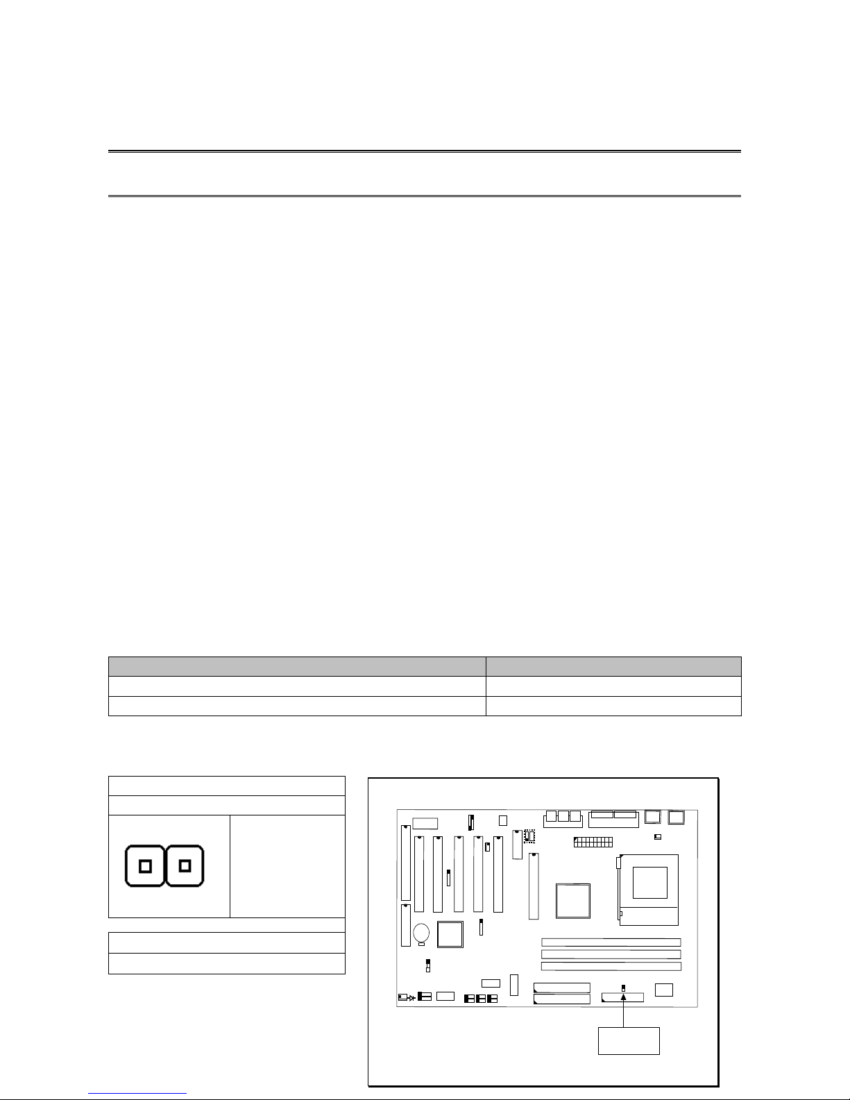
22..11 MMaaiinnbbooaarrdd SSeettttiinng
g
CCPPUU FFRROONNTT SSIIDDEE BBUUSS SSPPEEEEDD SSEETTTTIINNG
G
AMD K7 processor uses DDR transfer technology for its data and address busses that
generate 200MHz or 266MHz front side system bus speed. Our mainboard comes with
various models that support 200Mhz or 266Mhz FSB speed as follows:
MMooddeells
s
FFSSBB SSppeeeed
d
KKTT113333TTXX//KKTT113333BBXX//KKTT113333BBLL//KKTT33EEBBX
X
220000MMhhz
z
KKTT33AABBXX //KKTT33AABBL
L
226666MMhhz
z
To set the FSB speed, you need to enable or disable the JP8 (jumper 8) as follows:
220000MMhhz
z
JJPP 88 –– OOppeen
n
WWiitthhoouut
t
JJuummppeerr ccaap
p
iinnsseerrt
t
226666MMhhz
z
JJPP 88 SShhoorrt
t
JP8
123
4
A
B
C
JP8
WWiitthh JJuummppeer
r
ccaapp iinnsseerrt
t
22--1
1
H
H
H
a
a
a
r
r
r
d
d
d
w
w
w
a
a
a
r
r
r
e
e
e
I
I
I
n
n
n
s
s
s
t
t
t
a
a
a
l
l
l
l
l
l
a
a
a
t
t
t
i
i
i
o
o
o
n
n
n
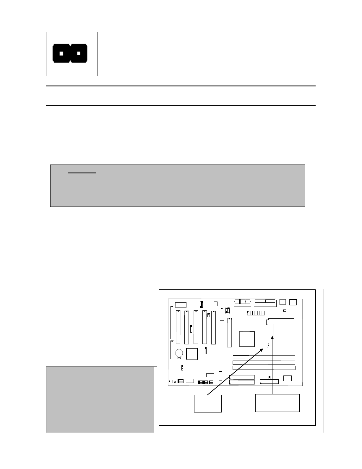
22..22 IInnssttaallllaattiioonn ooff PPrroocceessssoorr ((CCPPUU)
)
BBeeffoorree yyoouu iinnssttaallll tthhee AAMMDD pprroocceessssoorr,, mmaakkee ssuurree tthhaatt yyoouu hhaavvee aann aapppprroovveedd HHeeaatt SSiinnk
k
wwiitthh CCoooolliinngg FFaann.. WWiitthhoouutt pprrooppeerr hheeaatt ssiinnkk wwiitthh ccoooolliinngg ffaann wwiillll ddaammaaggee tthhee pprroocceessssoorr aannd
d
mmaaiinnbbooaarrdd.
.
CCaauuttiioonn!!
According to the documentation from AMD, Duron™ and
Athlon™ processors require larger heat sink. The rotation speed of the
cooling fan is 6,600 RPM or above. Thermal grease must be applied
between the heat sink and the CPU to improve heat dissipation. Also,
ensure that the heat sink is fastened securely on the CPU.
To install your AMD processor, please do the following:
1. Locate a small dot marked on top of the CPU. The marking indicate Pin 1 of the CPU.
2. Locate the Socket Pin 1 marking on the mainboard.
3. Push the lever sideway and lift it upwards to 90-degree angle. Insert the CPU into the
Socket. Please make sure that the CPU Pin 1 is insert to the socket Pin 1 location.
4. Install an approved heat sink
with cooling fan for proper
heat dissipation. Falling to
install a heat sink with cooling
fan may cause overheating and
burnout your CPU
5. Snap back the lever into place
Caution! Be careful not to
scrape the mainboard
when mounting a clamp-
style processor fan to
prevent damage to the
mainboard.
U
S
B
D
I
M
M
3
A
G
P
S
L
O
T
CPU
C
N
9
I
D
E
1
C
N
1
0
I
D
E
2
D
I
M
M
2
D
I
M
M
1
123
C
N
8
F
D
C
4
A
B
C
P
C
I
S
L
O
T
A
M
R
JP8
P
C
I
S
L
O
T
P
C
I
S
L
O
T
P
C
I
S
L
O
T
P
C
I
S
L
O
T
SOCKET A
Pin 1
22--2
2
H
H
H
a
a
a
r
r
r
d
d
d
w
w
w
a
a
a
r
r
r
e
e
e
I
I
I
n
n
n
s
s
s
t
t
t
a
a
a
l
l
l
l
l
l
a
a
a
t
t
t
i
i
i
o
o
o
n
n
n
22..33 IInnssttaalllliinngg ooff DDIIMMMM MMeemmoorry
y
This mainboard uses only Dual
Inline Memory Module. Sockets
are available for 3.3-volt
(power level) un-buffered
Synchronous Dynamic Random
Access (SDRAM) memory system
of 16, 32, 64, 128 or 256MB.
It’s support single-side or
double-side SDRAM DIMM
module and the maximum
memory size supported is
1536MB.
DIMM 1
DIMM 2
DIMM 3
D
I
M
M
3
D
I
M
M
2
D
I
M
M
1
123
4
A
B
C
JP8
NNoottee!! DDIIMMMM11 oorr DDIIMMMM22 mmuusstt bbee iinnssttaalllleedd ffiirrsst
t
22..44 IInntteerrnnaall CCoonnnneeccttoor
r
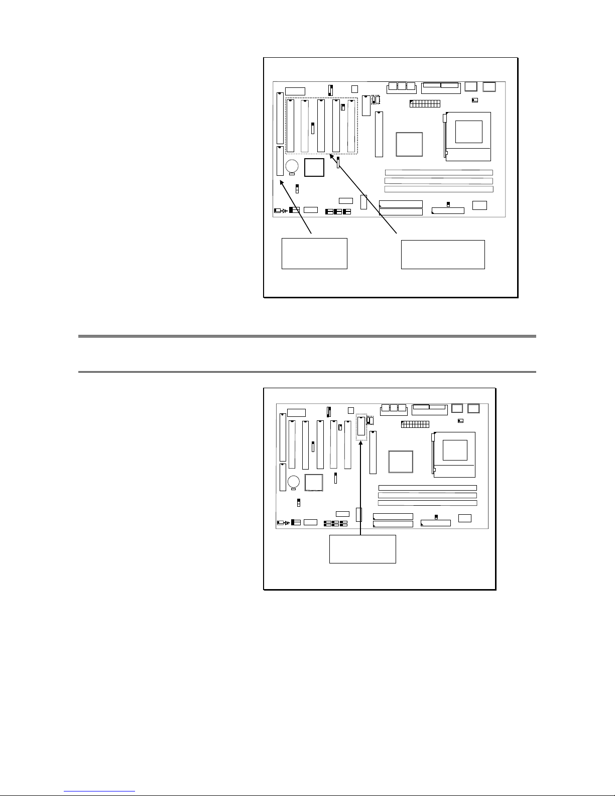
22..44..11PPCCII SSlloott aanndd IISSAA SSlloot
t
Both PCI and PCI expansion
cards may require IRQs, this
mainboard complies with Plug
and Play (PnP) specification that
allow automatic system
configuration whenever a PnP
compliant card is added. For PnP
card, IRQs are assigned
automatically for those available.
If older legacy cards that are not
support by the BIOS, please
contact your vendor for an ISA
Configuration Utility.
PCI slots
D
I
M
M
3
D
I
M
M
2
D
I
M
M
1
123
4
A B
C
JP8
ISA slots
22--3
3
H
H
H
a
a
a
r
r
r
d
d
d
w
w
w
a
a
a
r
r
r
e
e
e
I
I
I
n
n
n
s
s
s
t
t
t
a
a
a
l
l
l
l
l
l
a
a
a
t
t
t
i
i
i
o
o
o
n
n
n
22..44..22 AAMMRR SSlloot
t
This connector support a
specially designed audio and/or
modem card called Audio Modem
Riser.
Since main processing is done
through software and the
mainboard I/O controller, it’s
provide a low cost solution for
upgradeable Audio and/or
modem card.
AMR Slot
D
I
M
M
3
D
I
M
M
2
D
I
M
M
1
123
4
A B
C
JP8
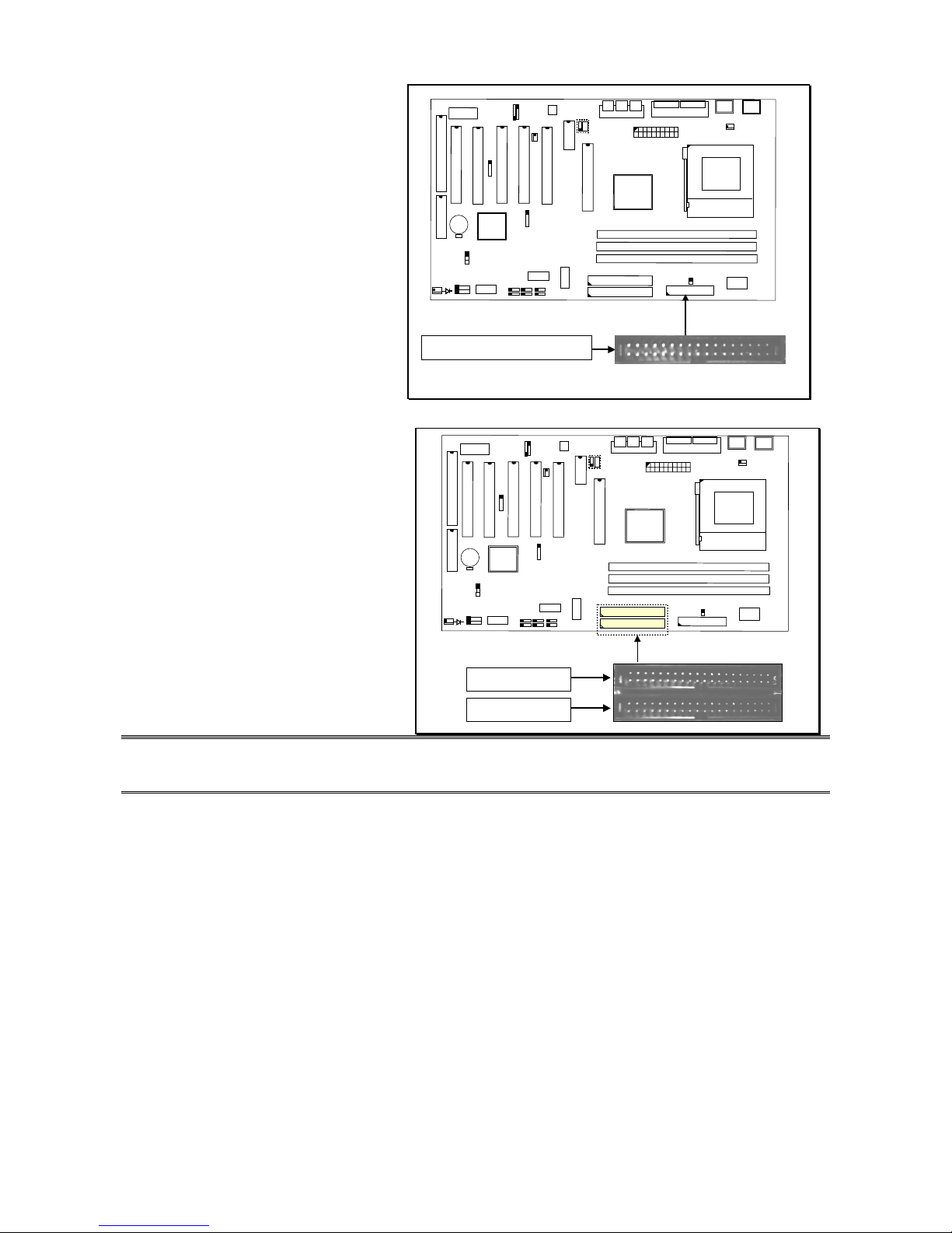
22..44..33 FFllooppppyy DDiisskk DDrriivve
e
CCoonnnneeccttoor
r
This connector support two
Floppy drives. Uses the ribbon
cable provided and make sure
that the red strip is connect to
PIN 1 of the connector.
CN8: FDC Connector
D
I
M
M
3
D
I
M
M
2
D
I
M
M
1
123
4
A
B
C
JP8
22..44..44 PPrriimmaarryy aanndd SSeeccoonnddaarry
y
IIDDEE CCoonnnneeccttoorrs
s
Each IDE connector supports two
IDE drives. If you install two hard
drives, you need to configure the
second drive to Slave mode.
Please refer to the hard drive
manual for appropriate jumper
setting.
CN10: IDE 2
CN9: IDE 1
D
I
M
M
3
D
I
M
M
2
D
I
M
M
1
123
4
A
B
C
JP8
22--4
4
H
H
H
a
a
a
r
r
r
d
d
d
w
w
w
a
a
a
r
r
r
e
e
e
I
I
I
n
n
n
s
s
s
t
t
t
a
a
a
l
l
l
l
l
l
a
a
a
t
t
t
i
i
i
o
o
o
n
n
n
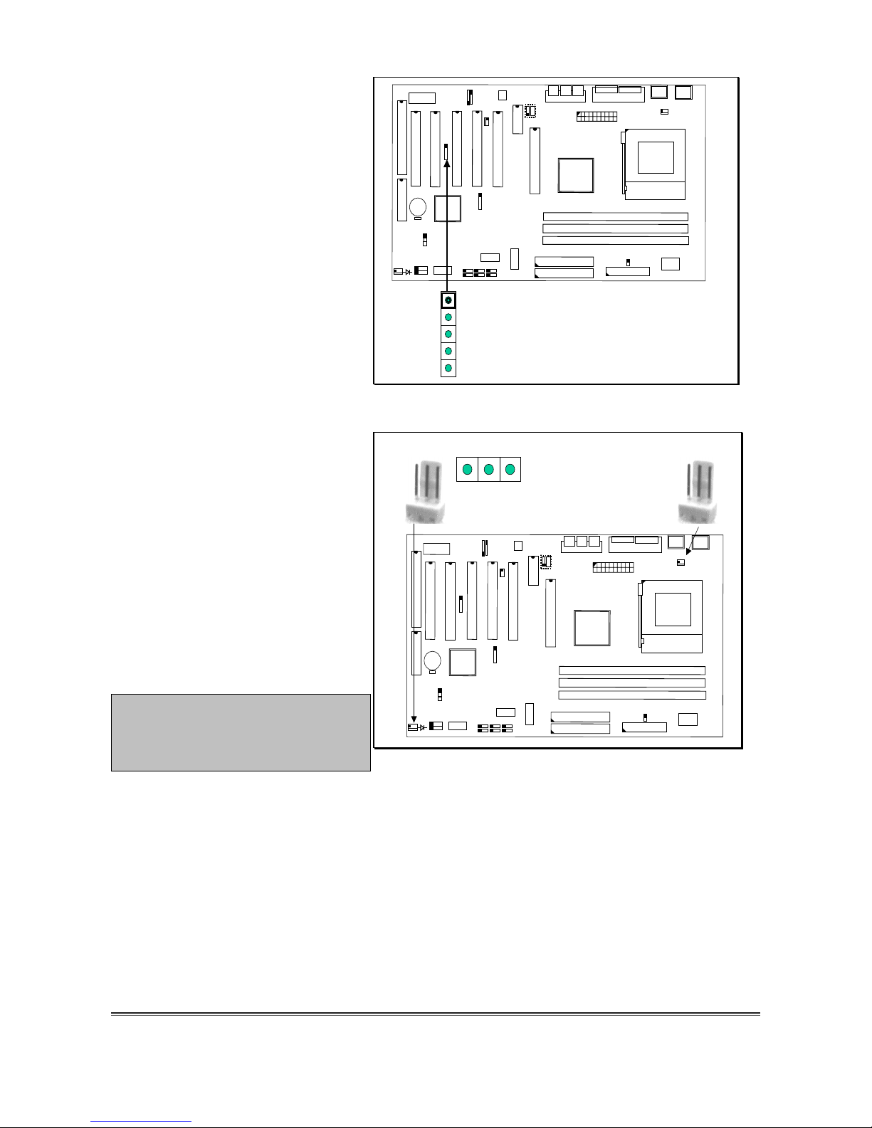
22..44..55 SSttaannddaarrdd IInnffrraarreedd ((SSIIRR)
)
CCoonnnneeccttoor
r
This IR connector (SIR) supports
optional wireless transmitting and
receiving infrared module.
You must configure the setting
through URAT2 to select whether
URAT2 is directed for use with COM
2 or IrDra.
123
4
A
B
C
JP8
1
2
3
4
5
( +5VDC )
(
NO CONNECTI ON )
(
IR RECEIVE )
(
GROUND )
(
IR TRANSMIT )
CN 12: IR (SIR) CONNECTOR
22..44..66 CCoooolliinngg aanndd CChhaassssiiss FFaan
n
PPoowweerr CCoonnnneeccttoor
r
Please install your cooling fan
power connector on CN13. If the
hardware-monitoring feature is
installed, you could monitor the
rotating speed of the CPU cooling
fan in your Windows operation
system.
Chassis Fan is to be installed on
CN17.
Warning! These are not
jumpers; do not place caps
over these pins.
123
4
A
B
C
JP8
CN13
1.Ground
2. +12V DC
3.Fan Sense Signal
1 2 3
CN17
22--5
5
 Loading...