

AZZA 810T User Manual

The AZZA 810T Mainboard Series
Cover Click Here
Table Of Contents Click Here
Introduction Click Here
Hardware Installation Click Here
BIOS Management Click Here
R
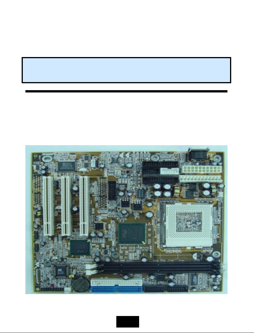
8102T USER’S MANUAL
Socket 370 AT Mainboard
8102T
810E2T
Document NO: 81 02ET - E1
Revision: 1.0V
Creation Date: 2001-08-01
1

User’s Notice
User’s Notice
Copyright
Copyright
User's
Notice
This publication contains i nformation that is protected by copyright. No part of i t may be reproduced in
any form or by any means or used to make any transformation adaptation without prior written permission
from the copyright holders. This publication is provided for informational purposes only. The manufacturer
makes no representations or warranties with respect to the contents or use of this manual and specifically
disclaims any express or implied warranties of merchantability or fitness for any particular purpose. The
user will assume the entire risk of the use or the results of the use of this document. The manufacturer
reserves the right to revis e this publication and make changes to i ts contents at any time, without prior
notice.
Trademarks
Trademarks
®
Microsoft
trademarks of Microsoft Corporati on. Intel Penti um !!!
Intel Corporation. Award is a registered trademark of Award Software, Inc. Other trademarks and
registered trademarks of products appearing in this publication are the properties of their respective
holders.
Package Checklist
Package Checklist
This package contains the following items:
•
•
•
•
•
•
•
•
If any of these items are missi ng or damaged, please contact your dealer or sales repres entative for
assistance.
Technical Support
Technical Support
If you require additional information, assistance during installation, please contact your dealer. Your
dealer will be able to provide the latest information. If you need additional help, please visit our web site
for technical support or e-mail to us.
MS-DOS®, WindowsTM, Windows® 95, Window® 98 and Windows® ME are registered
Mainboard Users manual
One IDE cable support ATA/33, ATA/66 or ATA100 IDE drives
One 34-pin floppy disk drive cable
One Driver Utility CD
One COM Port 1 and 2 Cable with bracket
One print port and PS/2 Cable with bracket
One Game and Audio Cable with bracket
One VGA Cable with bracket.
TM
and Intel Celeron
2001. All Rights Reserved.
TM
are r e gi stered t rademark s o f
2

Table Of Contents
Table Of Contents
Table Of Contents
Chapter 1:- Introduction
1.1. Overview ................................................................................................... 5
1.1.1. Mainboard Series ................................................................................... 6
1.1.2. Mainboard Dimensions ........................................................................... 6
1.1.3. Environmental Limitations ...................................................................... 6
1.2. Features and Specifications ...................................................................... 6
1.3. System Intelligence .................................................................................. 9
Chapter 2:- Hardware Installation
2.1. Installation Checklist ................................................................................ 10
2.2. Installation Steps ...................................................................................... 11
2.3. CPU, Memory and Expansion Slots ............................................................ 13
2.3.1. Installation of Processor (CPU) ............................................................... 13
2.3.2. Memory Modules ................................................................................... 13
2.3.3. PCI Slots ............................................................................................... 14
2.4. Internal Connectors .................................................................................. 14
2.4.1. AT Keyboard Connector .......................................................................... 14
2.4.2. PS/2 Mouse Connector ........................................................................... 15
2.4.3. Serial Port Connectors: COM1 and COM2 ................................................. 15
2.4.4. Parallel Port Connector: LPT1 ................................................................. 15
2.4.5. USB Connectors: USB1, USB2, USB3 and USB4 ........................................ 15
2.4.6. Floppy Disk Drive (FDD) ......................................................................... 16
2.4.7. Primary and Secondary IDE Connectors .................................................. 16
2.4.8. Standard Infrared Connector .................................................................. 16
2.4.9. CPU and Chassis Fan Connectors ............................................................ 17
2.410. AT Power Supply Connector .................................................................... 17
2.4.11. ATX Power Supply Connector .................................................................. 17
2.4.12. WOL (Wake-On-LAN) Connector ............................................................ 18
2.4.13. Audio/Game Port Connector .................................................................... 18
2.4.14. VGA Connector ...................................................................................... 18
2.4.15. CD Audio In Connector ........................................................................... 19
2.4.16. AIR Bus Connector ................................................................................. 19
2.4.17. Front Audio Connector ............................................................................ 19
2.5. System Panel Buttons and LED Connectors .............................................. 20
2.5.1. PW: Power On/Off and External Suspend Switch Connector ........................ 20
2.5.2. TL: Turbo LED Connector ......................................................................... 21
2.5.3. HL: IDE HDD LED Connector .................................................................... 21
2.5.4. RS: Reset Button Connector ..................................................................... 21
2.6. Speaker, Power LED and Key-Lock Connector .......................................... 21
2.6.1. Speaker Connector ................................................................................... 21
2.6.2. Front Panel LED and Key-Lock Connector ..................................................21
Page 5
Page 10
3

Table Of Contents
Table Of Contents
Table Of Contents
2.7. Jumper Settings .........................................................................................22
2.7.1. JP 1: OnNow Function ..............................................................................22
2.7.2. JP 2: Clear CMOS .....................................................................................23
2.7.3. JP 3: Clear Keyboard Password ..................................................................23
Chapter 3:- Managing The PC BIOS
3.1. AWARD BIOS CMOS Setup Utility ...........................................................24
3.2. Main Menu ..............................................................................................25
3.3. Standard CMOS Setup .............................................................................26
3.4. ADVANCED BIOS FEATURES ...................................................................28
3.5. ADVANCED CHIPSET FEATURES .............................................................31
3.6. INTEGRATED PERIPHERALS ...................................................................33
3.7. Power Management Setup ......................................................................37
3.8. PNP/PCI Configuration ...........................................................................40
3.9. Frequency/Voltage Control ....................................................................42
3.10. Load Optimized Defaults .........................................................................43
3.11. Set Supervisor Password ........................................................................43
3.12. Set User Password ..................................................................................44
3.13. SAVE & EXIT SETUP/EXIT WITHOUT SAVING ........................................45
Page 24
4
Introduction
Introduction
Chapter 1
Chapter 1
Chapter 1
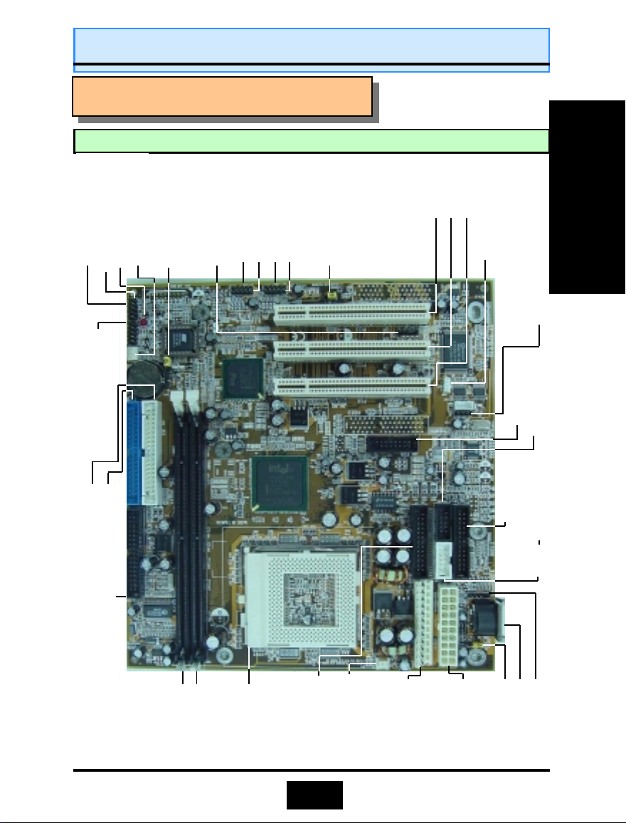
PWR LED/KBLOCK
LED Connectors
CN 10: IDE 2
CN 17: CPU Fan 2
JP2: Clear CMOS
SPK (speaker)
LED 1
System Panel and
CN 9 : IDE 1
-
Introduction
-
Introduction
-
Introduction
1.1
MAINBOARD LAYOUT
1.1
MAINBOARD LAYOUT
1.1
MAINBOARD LAYOUT
Password
CN 12: IR
USB 2
USB 1
USB 4
USB 3
Introduction
JP3: Clear K/B
PCI 3
CN16: WOL
PCI 1
PCI 2
CN 21: CD-IN
CN 3 : COM 1
CN 19: VGA
CN 4 : COM 2
CN 18: Game/
Audio
CN 8: FDC
CN 14: AT
Power
DIMM 1
DIMM 2
Socket 370
CN 5: LPT
Fan 1
CN 13: CPU
Connector
CN 15: ATX
Power
Connector
Function
CN 2: M/S
CN 1: K/B
JP1: OnNow
5

Introduction
Introduction
1.1.1. Mainboard Series
The 810 mainboard series has two models. They are:
1. 8102T
2. 810E2T
1.1.2. Mainboard Dimensions
Width & Length: 222 mm x 210 mm. 8.27 inches x 8.74 inches
Height: 1 1/2 inches
PCB Thickness: 1.6 mm
Weight: 18 ounces.
Introduction
1.1.3. Environmental Limitations
Operating Temperature: 10°C to 40°C . (50°Fto 104°F)
Required Airflow: 50 linear feet per minute across CPU.
Storage Temperature: - 40°C to 70°C. (- 40°F to 158°F)
Humidity: 0 to 90% non-condensing.
Altitude: 0 to 10,000 feet
1.2
Features and Specifications
1.2
Features and Specifications
Processor
Supports Intel® Socket 370 0.25ц Celeron, 0.18ц Celeron, 0.18ц Pentium III or
VIA Cyrix C3
Chipset
Intel FW82810 (for 8102T) or Intel FW82810E (for 810E2T) and FW82801BA
Super I/O
Winbond W83627SF
CPU Switching Voltage Regulator
Equipped with a switching voltage regulator that automatically detects +1.30V to
+3.50V DC power supply.
System Memory
• 8MB to 512MB of 3.3V SDRAM memory.
• Two 168-pin DIMM sockets.
• Supports PC-100 SDRAM DIMM and PC-133 SDRAM DIMM.
6
Introduction
Introduction
Expansion Slots
Three dedicated PCI slots, and one (optional) CNR (Communication Network
Riser) slot. The CNR slot provides the opportunity to install a flexible and cost
reduced method of implementing LAN, home networking, DSL, USB, wireless,
audio and modem subsystems widely used in today's "connected PCs".
Onboard Audio Featur es
• Supports Microsoft ® DirectSound/DirectSound 3D.
• AC97 supported full duplex, independent sample rate converter for audio
recording and playback.
Front Audio Port (Optional)
For use with a Front Utility Panel that connects Ear Phone, Microphone and Audioin. For more details, please consult your dealer.
Word Size
Data Path: 8-bit, 16-bit, 32-bit, 64-bit.
Address Path: 32-bit.
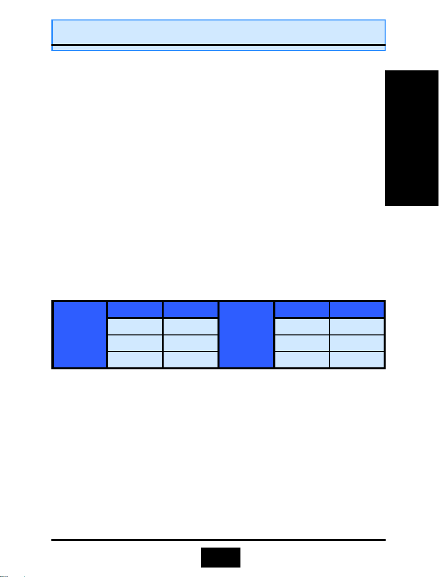
FRONT SIDE BUS FREQUENCY
Supports 66 MHz, 100 MHz and 133 MHz FSB. Refer to the following table:
8102T
8102T
8102T
CPU SDRAM CPU SDRAM
66 MHz 100 MHz 66 MHz 100 MHz
100 MHz 100 MHz 100 MHz 100 MHz
133 MHz 133 MHz 133 MHz 100 MHz
810E2T
810E2T
810E2T
Introduction
BIOS
• Award BIOS, Windows ® 95/98 Plug and Play compatible.
• Supports SCSI sequential boot-up.
• Flash EPROM for easy BIOS upgrades (2 Mbit).
• Supports DMI 2.0 function.
Desktop Management Interface (DMI)
The mainboard comes with a DMI 2.0 built into the BIOS. The DMI utility in the
BIOS will automatically record different system configuration information and
store this information in the DMI pool, which is a part of the system board's Plug
and Play BIOS. DMI, along with the appropriately networked software, is designed
for easy inventory, maintenance and simplified troubleshooting of computer systems.
7

Introduction
Introduction
WOL (Wake-On-Lan) Port (optional)
One WOL connector supports Wake-On-LAN functionality.
USB Ports
The mainboard is equipped with four internal USB connectors. USB allows data
exchange between your computer and a wide range of simultaneously accessible
external Plug and Play peripherals. ( Cable set for two connectors are optional and
is sold separately).
IrDA Interface (optional)
The mainboard is equipped with an IR and CIR IrDA connector for wireless
connectivity between your computer and peripheral devices. It supports peripheral
Introduction
devices that meet the HPSIR or ASKIR standard.
Connectors
• One connector for SIR and one connector for CIR IrDA interface.
• One floppy drive interface supports up to two 2.88MB floppy drives.
• One ATX and one AT power supply connector.
• One CPU and one chassis fan connector.
• One CD audio-in connector.
• One Front Audio Connector supports a Front Utility Panel.
• Two NS16C550A-compatible DB-9 serial port connectors (UARTs).
• One SPP/ECP/EPP DB-25 parallel port.
• One internal PS/2 mouse port connector.
• One AT keyboard port.
• One Audio/Game connector.
• One VGA connector.
PCI Bus Master IDE Controller
Two PCI IDE interfaces support up to four IDE devices.
•
Support ATA/33, ATA/66 and ATA100 hard disk drives.
•
PIO Mode 3 and Mode 4 Enhanced IDE (data transfer rate up to 16.6MB/
•
sec.).
Bus mastering reduces CPU utilization during disk transfer.
•
Supports ATAPI CD-ROM, LS-120 and ZIP
•
8

Introduction
Introduction
Intelligence
1.1.33 Intelligence
Dual Function Power Button
Depending on the setting in the Soft-Off By Power-Button field of the Power
Management Setup, this switch allows the system to enter the Soft-Off or Suspend
mode.
External Modem Ring-on ( optional)
The Modem Ring-on feature allows the system that is in the Suspend mode
or Soft Power Off mode to wake-up/power-on to respond to incoming calls. This
feature supports external modem only.
RTC Timer to Power-on the System
The RTC installed on the system board allows your system to automatically
power-on on the set date and time.
Wake-On-LAN Ready (optiona l)
The Wake-On-LAN function allows the network to remotely wake up a Soft
Power Down (Soft-Off) PC. Your LAN card must support the remote wakeup
function. The 5VSB power source of your power supply must be at least 720mA.
ACPI Ready
The mainboard is designed to meet the ACPI (Advanced Configuration and
Power Interface) specification. ACPI has energy saving features supporting OS
Direct Power Management (OSPM) for round the clock PC operation.
Introduction
9
Hardware Installation
Hardware Installation
Chapter 2
Chapter 2
Chapter 2
The following is a checklist of all the expansion slots, jumpers and connectors that
should be configured on your mainboard before you can run your pc.
CPU Slot
DIMM Slots
PCI Slots
JP1
JP2
JP3
CN1
CN2
CN3
CN4
CN5
CN6
Hardware Installation
CN7
CN8
CN9
CN10
CN13
CN14
CN15
CN17
CN18
CN19
CN21
CN30
CN31
-
Hardware
-
Hardware
-
Hardware
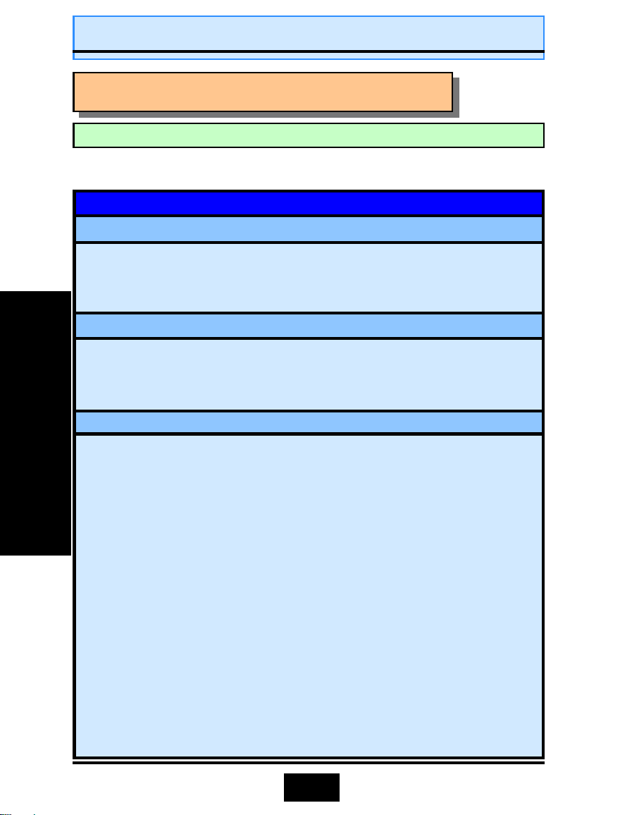
2.1. Installation Check List
2.1. Installation Check List
2.1. Installation Check List
Installation Checklist
Expansion Slots and Sockets
Socket 370 supports Celeron, Pentium III and Cyrix C3.
Two 168 pin slots that support upto 512 MB SDRAM.
Three 32 bit PCI Slots.
OnNow Function Only on ATX Power
Clear CMOS Data
Clear Keyboard Password Only on ATX Power
AT Keyboard Connector K/B
PS/2 Mouse M/S
Serial Port 1 COM1
Serial Port 2 COM2
Parallel Port LPT
Universal Serial Bus 1 USB1
Universal Serial Bus 2 USB2
Floppy Disk Drive FDC
Primary IDE IDE1
Secondary IDE IDE2
CPU Fan 1 CPU Fa n1
AT Power AT
ATX Power ATX
CPU Fan 2/Chassis Fan CPU Fan2
Audio/Game Port Audio/Game
VGA Video Port VGA
CD-In without housing CD-In
Universal Serial Bus 3 USB3
Universal Serial Bus 4 USB4
Jumpers
Internal Connectors
10
PW
TL
HL
RS
PWR-LED
SPK
KBLOCK
CN12
CN16
CN25
CN39
Hardware Installation
Hardware Installation
Installation Checklist (Continu ed)
System Panel Buttons and LED Connectors
Power On/Off and Suspend Switch Connector.
Turbo LED
HDD LED Connector
Reset Button LED Connector
Speaker, Power LED and Keyboard Lock Connector
Power LED
Speaker Connector
Keyboard Lock Connector
Optional Connectors
Infrared Connector IR
Wake-On-LAN Connector WOL
AIR BUS Interface AIRBUS
Front Audio Interface Front AUDIO
Hardware Installation
A Diagram of the Expansion Slots, Jumpers and Connectors can be seen
on the following page
2.2. Installation Steps
You need to complete the following installation steps before you can use your PC.
Check and Set the Mainboard Settings.
•
Install the Central Processing Unit (CPU).
•
Install the Memory Modules.
•
Install the Expansion Cards.
•
Connect the Ribbon Cables, Panel Wires and the Power Supply.
•
Setup the system BIOS
•
Before you start
you use a grounded anti-static mat. We further recommend that you attach
an anti-static wristb and, which is grounded at th e same location as the mat,
to your wrist.
installing your mainb oard we strongly recommend that
11
Hardware Installation
Hardware Installation
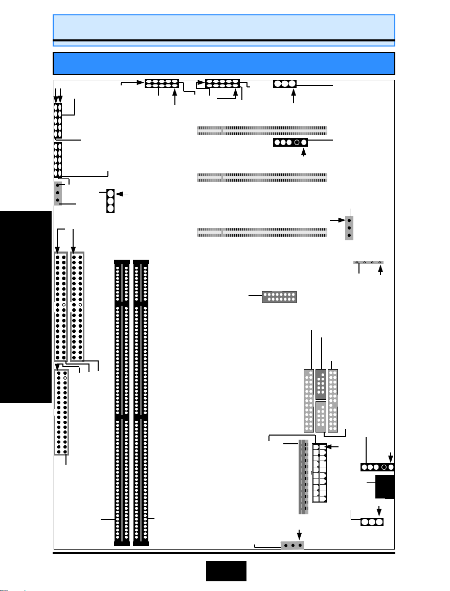
Expansion Cards, Connectors and Jumpers For The 8102T/810E2T
1
PWR-LED/KBLOCK
SPK
System Panel Buttons and
LED Connectors
1
CN 31: USB4
1
1
CN 30: USB3
PCI 3 PCI 2
USB2
CN 7:
USB1
CN 6:
JP3:
Password
1
Clear K/B
CN 12:
Hardware Installation
CN 8:
FDC
CN 3:
CN 5:
COM1
LPT
I R
CN 16:
WOL
1
1
CN 22:
CN 21:
1
CD Audio In
CD Audioo In
CN 18:
Game/Audio
CN 4:
COM2
CN 2:
MS
1
JP1:
K/B PWR
CN 1:
K/B
1
1
1
1
JP2:
CN 17:
Clear CMOS
CPU FAN2
1
CN 10:
CN 9:
1
IDE 1
IDE 2
DIMM 2
1
PCI 1
CN 19:
VGA
CN 14:
CN 15:
AT Power Supply
ATX Power Supply
CN 13:
DIMM 1
CPU FAN1
1
12
Hardware Installation
Hardware Installation
2.3. CPU, Memory and Expansion Slots
2.3. CPU, Memory and Expansion Slots
2.3. CPU, Memory and Expansion Slots
2.3.1 Installation of Processor (CPU)
Before you install the processor, make sure that you have an approved Heat Sink
with Cooling Fan. Without proper heat sink with cooling fan will damage the processor and mainboard.
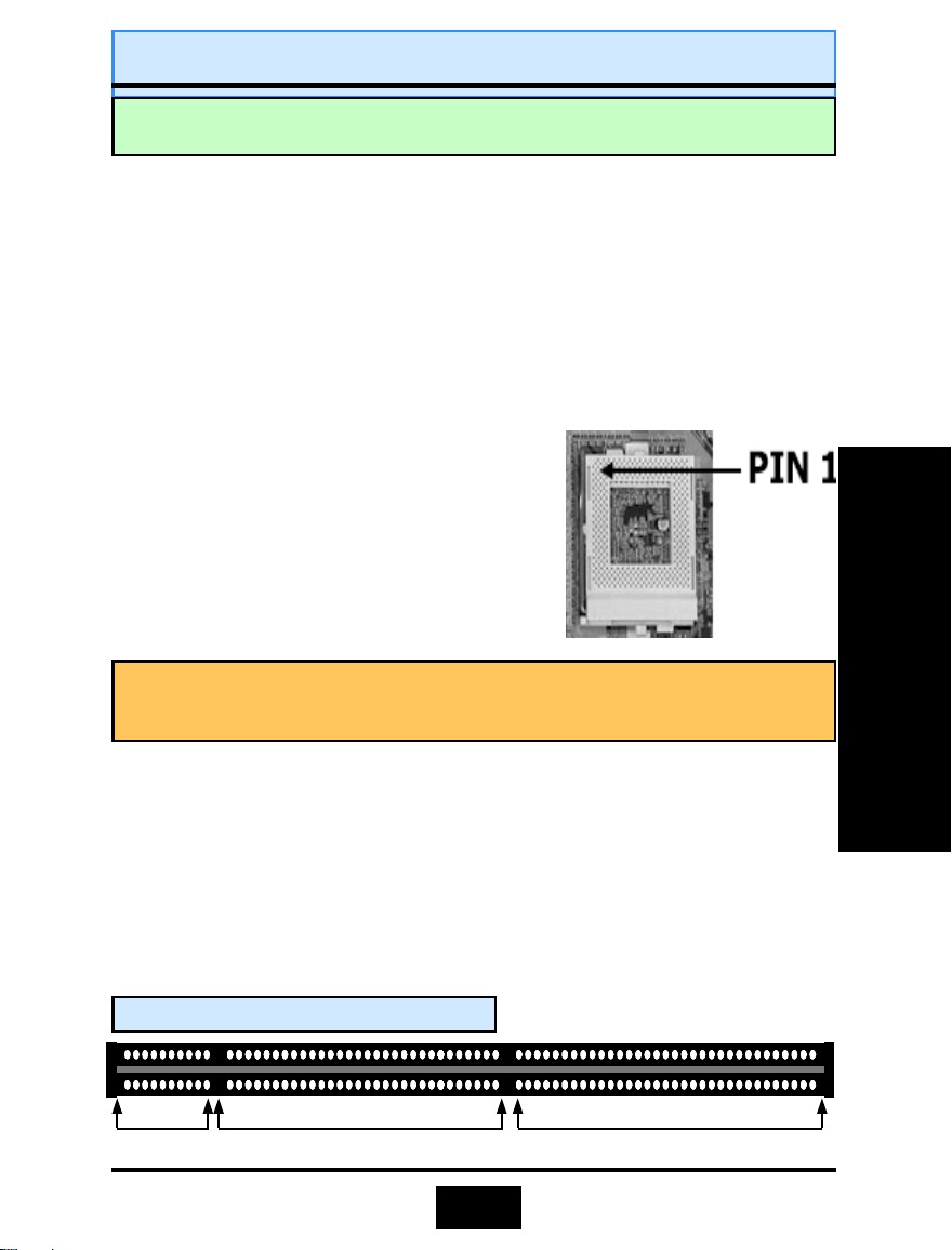
To install your processor, please do the following:
1. Locate a small dot marked on top of the CPU. The marking indicate Pin 1 of
the CPU.
2. Locate the Socket Pin 1 marking on the mainboard.
3. Push the lever sideway and lift it upwards
to 90-degree angle. Insert the CPU into the
Socket. Please make sure that the CPU Pin
1 is insert to the socket Pin 1 location.
4. Snap back the lever into place.
5. Install an approved heat sink with
cooling fan for proper heat dissipation.
Falling to install a heat sink with cooling
fan may cause overheating and burnout
your CPU.
Caution! Be careful not to sc rape the mainboard when mounting a cla mpstyle processor fan to prevent damage to the mainboard.
Hardware Installation
2.3.2. Memory Modules
These mainboards all have two 168-pin SDR DIMM slots and are able to support a
maximum memory (SDRAM) of 512 MB. The SDR DIMM slots are located on the
right hand side of the board. To install the DIMM’s into these slots, make sure the
white lever at each side of the slot has been pulled down to an angle of
approximately 45°. Make sure that the DIMM is in the correct orientation. Place
the DIMM on the slot and push down firmly.The white levers will come back up
and lock the module in place.
Top View of a 168 pin DIMM Slot
10 pins 30 pins 44 pins
13
 Loading...