

Page 1

Azure Wave AW-GM100 Wireless LAN module
User Guide
Release History:
0.96 2005/8/29 First Release
Page 2

Contents:
Section 1 Getting Start.........................................................................................................................1-3
1.1 Overview....................................................................................................................................1-3
1.2 Equipment..................................................................................................................................1-3
1.2.1 Standard Mini-PCI Adapter ............................................................................................1-3
1.2.2 Antenna...........................................................................................................................1-3
1.3 System Requirement..................................................................................................................1-4
1.4 Specification Summary..............................................................................................................1-4
Section 2 Windows Driver Installation ................................................................................................... 6
2.1 Utility............................................................................................................................................ 6
2.1.1 Production Options ............................................................................................................ 6
2.1.2 Welcome............................................................................................................................. 7
2.1.3 Customer Information........................................................................................................ 8
2.1.4 Setup Type.......................................................................................................................... 8
2.1.5 Read Install ........................................................................................................................ 9
2.1.6 Finish................................................................................................................................ 10
2.1.7 Odyssey ~ Welcome......................................................................................................... 10
2.1.8 Odyssey ~ License Agreement......................................................................................... 11
2.1.9 Odyssey ~ Finish.............................................................................................................. 11
2.2 Device Driver.............................................................................................................................. 12
Section 3 Network Management Software ........................................................................................... 12
3.1 Marvell Client Configuration...................................................................................................... 12
3.2 Odyssey Client Management...................................................................................................... 13
Appendix A: Release History ............................................................................................................. 14
Page 3

Section 1
1.1 Overview
This document describes how to install and use the AzureW ave GM100 Mini-PCI a dapter. So does the
software command line interface to test the installed adapter. In section 1, we introduce you the basic
instruction manual for GM100. In section 2, we represent the software installation for GM100. In
section 3, we introduce the command line interface as test reference.
1.2
Equipment
1.2.1 Standard Mini-PCI Adapter
AzureWave GM100 is a standard Mini-PCI
interface adapter that designs in a wireless
LAN module for wireless network connection.
Getting Start
The system would install GM100 should provide
Mini-PCI interface to be adapter connection.
The overall hardware setup of GM100 is
shown in right figure. It shows the installation
of standard Mini-PCI adapter.
1.2.2
There are total two antenna connectors on the GM100. The minimal installation is one antenna. Two
antenna installation is applied to enhance data receive. The antenna should satisfy the connector on
the adapter. Please reference the following figure.
Antenna
Page 4

1.3
System Requirement
The only requirement of system is to provide Mini-PCI slot and support PCI device. AzureWav e GM100
represents as a standard PCI device in system platform that satisfies Plug-And-Play specification.
Standard PCI device access could detect GM100 without problem. Then y ou could follow the softw are
installation, descript in later sections.
1.4
Specification Summary
Host system connections
Interface
Date transfer rate
z Mini-PCI
z 33Mhz with 64-bit data length
Wireless LAN (WLAN) environment connections
WLAN Interface
WLAN transfer rate
z Multimode features
z Fully complies with IEEE 802.11 b/g specifications
z IEEE 802.11 data rates of 1 and 2 Mbps
Page 5

z IEEE 802.11b data rates of 5.5 and 11 Mbps
z IEEE 802.11g data rates of 6, 9, 12, 18, 24, 36, 48, and 54 Mbps for
multimedia content transmission
z IEEE 802.11a data rates of 6, 9, 12, 18, 24, 36, 48, and 54 Mbps for
multimedia content transmission
z Proprietary data rate of 22 Mbps (802.11b)
WLAN Frequency band
Operation Channel
Compatibility
Security
z 2.4 ~ 2.497 GHz ((Industrial Scientific Medical Band)
z Channel 1 ~ 11 for Tiawan ,USA, CANADA
z Fully compatible to IEEE 802.11 b/g devices
z WEP 64- and 128-bit encryption
z WPA (Wi-Fi Protected Access)
z AES hardware implementation as part of 802.11i security standard
Antenna At most two antennas
z Supports Ad Hoc and Infrastructure modes
z Supports Contention Free (CF)-Poll and CF-ACK for operation under
Point Coordination Function (PCF)
z Supports Request to Send (RTS)/Clear to Send (CTS) for operation
under Distributed Coordination Function (DCF)
z Hardware filtering of 64 multicast and 96 unicast addresses and
additional software options
z Support for 802.11e Quality of Service (QoS), On-chip Tx and Rx
FIFOs for maximum throughput
z Supports Open System and Shared Key Authentication services
z Supports long and short preamble
Page 6

Section 2
The supported Windows® platforms are Windows 98®, Windows Millennium®, Windows 2000®,
Windows XP® and Windows 2003®.
In the software package, there are two folders, Utils and Inf, each represents specifically for utility
and windows installation file. Under Utils folder, the Mrv8000x.exe leads you to install AzureWave
GM100 utility step-by-step. In INF folder, we place the necessary file for manually device driver
installation on each Windows® platform at specific folder.
2.1
Utility
Under Utils folder, you have to double click Mrv8000x.exe to start the utility installation.
In the following sections, we introduc e you the step to finish the easy installation.
2.1.1
; Marvell Liberates Client Configuration Manger
Production Options
Windows Driver Installation
Select to install Marvel Liberates Client
Configuration Manager in later steps.
You could choose to apply Windows
Zero Configuration for wireless LAN
network that Windows XP and above
version platform provide the new
feature.
; Odyssey Client Manager for Marvel
Select to install Odyssey Client Manager
in later steps. Odyssey Client Manager
is a network connection management
utility to help you setup network
configuration.
Once you made decision of desired utilities, press “Install” button to activate following steps.
Page 7

2.1.2
The next step is the welcome
scene and then the license
dialogs. Only if you agree the
license then you could go to next
step. Please read the contents of
license agreement before going
to next step.
Welcome
Page 8

2.1.3
Enter your information to the
two edit-boxes by following the
instruction above them. You
could decide to open the use
right of configuration utility to
either everyone whom could
login this system or the current
user for system management
purpose.
Customer Information
2.1.4
In this step, you could select
either “Complete” or “Custom” as
the installation type. The
complete type will directly lead
you to section 2.1.5. In this type,
program location is fixed to
install on the “program
files\marvell” folder of boot
disk. Instead, you could choose
custom type to decide the
location you desire to install the
program.
Setup Type
Page 9

In this step, you could decide the
location to install the program.
Press “Change” button to browse
the folder and location you
prefer.
2.1.5 Read Install
This step is the last chance you
could roll back to previous step
before starting installation. As
you decide to install
configuration utility, press
“Install” button to start program
installation.
Page 10

2.1.6
After a while with progress
dialog running, shows up the
latest step, finish dialog, to
inform you all the program had
been installed completely.
Press “Finish” button to close
setup program.
Finish
2.1.7
This step starts the installation
of Odyssey client management
utility .
Odyssey ~ Welcome
Page 11

2.1.8
You should agree the license
agreement before going to next
step.
Odyssey ~ License Agreement
2.1.9
When you see this step, all
Odyssey components are
installed. Press “Finish” button
to close setup.
Odyssey ~ Finish
Page 12
Device Driver
2.2
Installation of the driver allows access to the hardware memory space. The following files are
required:
z MWLAN.inf
z windrvr.sys
To install the driver, boo-up with a Mini PCI installed. Follow the prompts of the Wizard and point to
the MLAN.inf file for installation.
Section 3
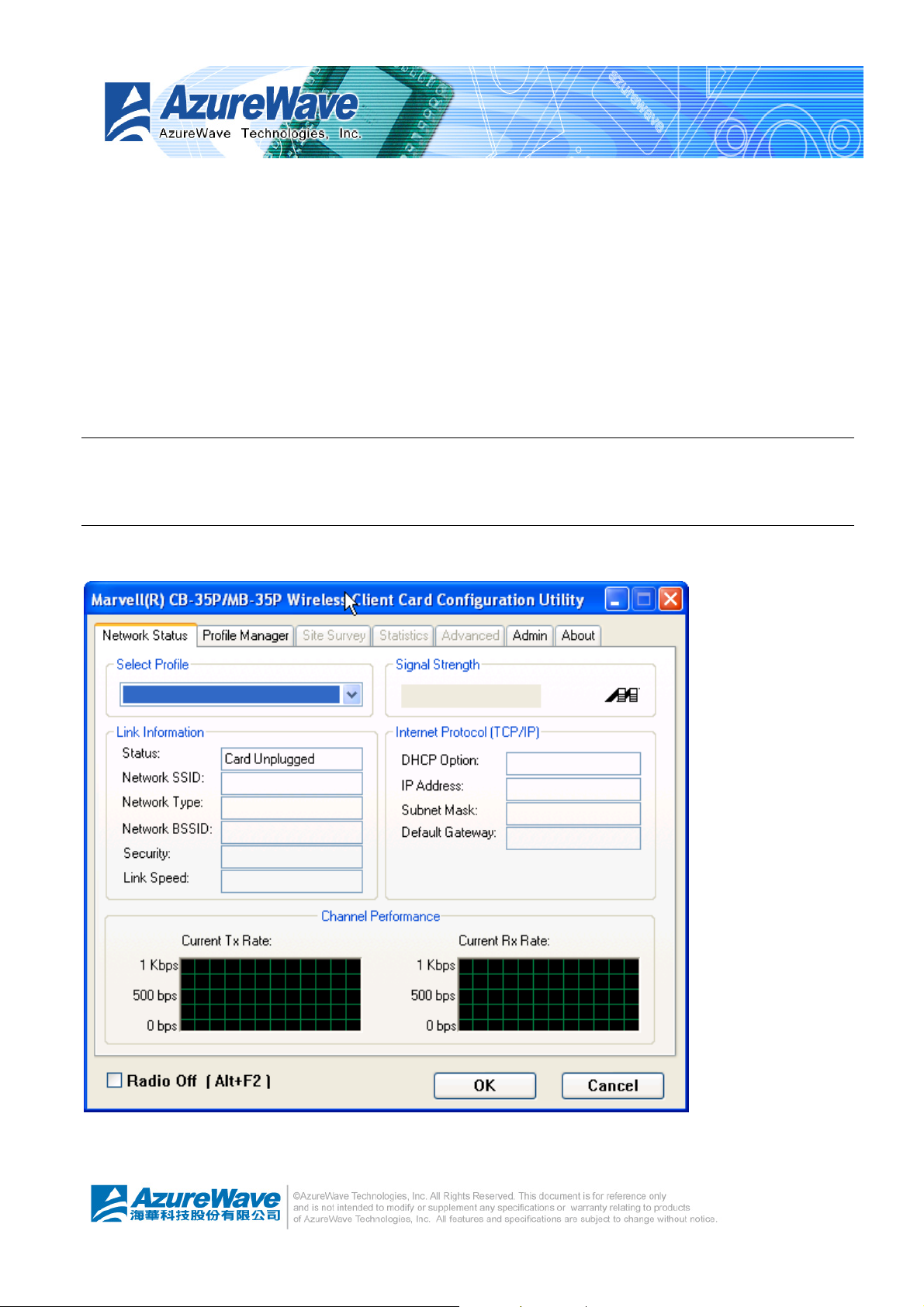
3.1 Marvell Client Configuration
Network Management Software
Yo u could get device status and network throughput analysis of Marvell 35P from this utility as above
figure.
Page 13
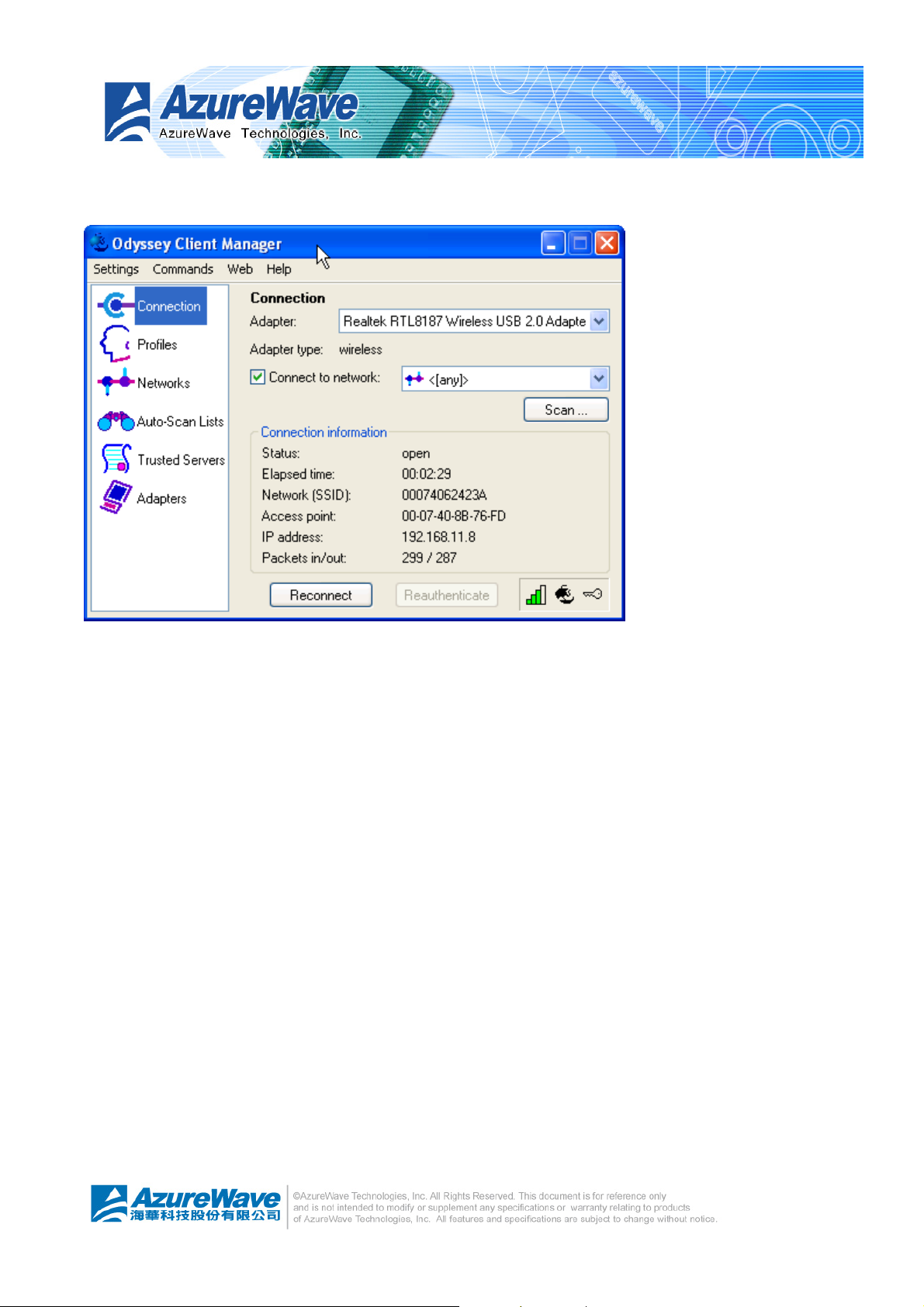
Odyssey Client Management
3.2
Odyssey provides easy use user interface to help you configure network connecti on. You could sel ect
the candidate wireless LAN adapter to build up desired configuration.
z Connection
You could setup network connections in this page.
z Profiles
You could create and manage profiles of access point that this station would become.
z Networks
You could create and manage profiles of connected access point.
z Auto-Scan Lists
This page periodically scans the wireless node inside the validate range.
z Trusted Servers
You could add and manage trusted network nodes
z Adapters
Page 14

You could review network adapter on this system.
Appendix A:
Release History
0.96 2005/8/29 First Release
Page 15

Federal Communication Commission Interference Statement
This equipment has been tested and found to comply with the limits for a
Class B digital device, pursuant to Part 15 of the FCC Rules. These limits
are designed to provide reasonable protection against harmful interference in
a residential installation. This equipment generates, uses and can radiate
radio frequency energy and, if not installed and used in accordance with the
instructions, may cause harmful interference to radio communications.
However, there is no guarantee that interference will not occur in a particular
installation. If this equipment does cause harmful interference to radio or
television reception, which can be determined by turning the equipment off
and on, the user is encouraged to try to correct the interference by one of the
following measures:
- Reorient or relocate the receiving antenna.
- Increase the separation between the equipment and receiver.
- Connect the equipment into an outlet on a circuit different from that
to which the receiver is connected.
- Consult the dealer or an experienced radio/TV technician for help.
This device complies with Part 15 of the FCC Rules. Operation is subject to
the following two conditions: (1) This device may not cause harmful
interference, and (2) this device must accept any interference received,
including interference that may cause undesired operation.
FCC Caution: Any changes or modifications not expressly approved by the
party responsible for compliance could void the user's authority to operate this
equipment.
IMPORTANT NOTE:
FCC Radiation Exposure Statement:
This equipment complies with FCC radiation exposure limits set forth for an
uncontrolled environment. This equipment should be installed and operated
with minimum distance 20cm between the radiator & your body.
This transmitter must not be co-located or operating in conjunction with any
other antenna or transmitter.
IEEE 802.11b or 802.11g operation of this product in the U.S.A. is
firmware-limited to channels 1 through 11.
Page 16

This device is intended only for OEM integrators under the following
conditions:
The antenna must be installed such that 20 cm is maintained between the
antenna and users, and
The transmitter module may not be co-located with any other transmitter or
antenna.
As long as 2 conditions above are met, further transmitter test will not be
required. However, the OEM integrator is still responsible for testing their
end-product for any additional compliance requirements required with this
module installed (for example, digital device emissions, PC peripheral
requirements, etc.).
IMPORTANT NOTE: In the event that these conditions can not be met (for
example certain laptop configurations or co-location with another transmitter),
then the FCC authorization is no longer considered valid and the FCC ID can
not be used on the final product. In these circumstances, the OEM integrator
will be responsible for re-evaluating the end product (including the transmitter)
and obtaining a separate FCC authorization.
End Product Labeling
This transmitter module is authorized only for use in device where the antenna
may be installed such that 20 cm may be maintained between the antenna
and users. The final end product must be labeled in a visible area with the
following: “Contains TX FCC ID: TLZ-GM100”.
Manual Information That Must be Included
The OEM integrator has to be aware not to provide information to the end
user regarding how to install or remove this RF module in the users manual of
the end product which integrate this module.
The users manual for OEM integrators must include the following information
in a prominent location “ IMPORTANT NOTE: To comply with FCC RF
exposure compliance requirements, the antenna used for this transmitter must
be installed to provide a separation distance of at least 20 cm from all persons
and must not be co-located or operating in conjunction with any other antenna
or transmitter.
 Loading...