

Page 1

MSP3880W Series
PCI 56K MODEM
Users Manual
Version 1.0
Page 2
WARNING
Before installing the Modem card ensure the PC is switched OFF and the mains cord removed. If servicing the
Modem card ensure the PC is switched OFF, the mains cord unplugged and the Telecommunications Line cord is
disconnected from the Modem Card.
EUROPEAN NETWORK COMPATIBILITY DECLARATION
The equipment has been designed to work in the public switched telephone networks (PSTN) in the following countries:
Denmark, Finland, France, Germany, Great Britain, Italy, Netherlands, Norway, Spain, Sweden, Portugal, Ireland,
Switzerland, Austria, Iceland.
The equipment may have interworking difficulties in PSTN networks in other countries. Please contact your equipment
supplier if it is desired to use the equipment on another network.
Electrical Safety
Before installing this equipment you must ensure that the power drawn by this card, together with the host and any
auxiliary cards drawing power from the host, is within the rating of the host power supply.
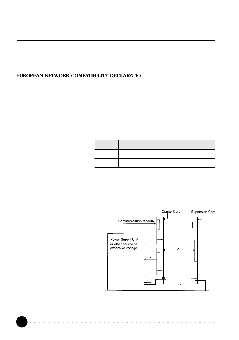
The equipment must be installed such that
with the exception of the connections to
the host, clearance and creepage
distances shown in the table below are
maintained between the card and any
other assemblies that use or generate a
voltage shown in the table.
Clearance Creepage (mm)
2.0 2.4 (3.8) Up to 50 Vrms or Vdc
2.6 3.0 (4.8) Up to125 Vrms or Vd c
4.0 5.0 (8.0) Up to 250 Vrms or Vdc
4.0 6.4 (10.0) Up to 300 Vrms or Vdc
The larger distance shown in brackets applies where the local environment within the host is subject to conductive
pollution or dry non-conductive pollution which could become conductive due to condensation. Failure to maintain
these minimum distances would invalidate the approval.
The analogue telecommunications interface is intended to be connected to telecommunication network voltage (TNV)
circuits which may carry dangerous voltages. The telephone cord must remain disconnected from the telecommunications
system until the card has been installed within a host which provides the necessary protection of the operator.
If it is subsequently desired to open the host equipment
for any reason, the telephone cord must be
disconnected prior to effecting access to any internal
parts which may carry telecommunication network
voltages.
Voltage used or Generated by Host
or Other Cards
Safety level of the various connectors:
Telephone Line Connector = TNV3
PCI connector = SELV
These indications are classified as per safety
standards EN60950/A4:
TNV3: Telecommunications Network Voltage
SELV: Safety Extra Low Voltage
Except for the edge connector which plugs into the hosts expansion slot, clearance distance (Xmm) and creepage
distance (Ymm) as given in the above table, must be maintained between the communication card and any other
assemblies which use or generate a hazardous voltage.
○○○○○○○○○○○○○○○○○○○○○○○○○○○○○○○○○○○○○○○○○
2
Page 3

PAN EUROPEAN APPROVAL REGULATORY NOTE
The equipment has been approved under CTR21. For such product, the following statement is required :
This equipment has been approved in accordance with Council Decision 98/482/EC for Pan European single terminal
connection to the Public Switched Telephone Network (PSTN). However, due to differences between the individual
PSTNs provided in different countries the approval does not, of itself, give an unconditional assurance of successful
operation on every PSTN network termination point.
In the event of problems, you should contact your equipment supplier in the first instance
Dieses Geraet wurde gemaess der Entscheidung 98/482/EG des Rates europaweit zur Anschaltung als einzelne
Endeinrichtung an das oeffentliche Fernsprechnetz zugelassen. Aufgrund der zwischen den oeffentlichen Fernsprechnetzen
verschiedener Staaten bestehenden Unterschiede stellt diese Zulassung an sich jedoch keine unbedingte Gewaehr fuer
einen erfolgreichen Betrieb des Geraets an jedem Netzabschlusspunkt dar.
Falls beim Betrieb Probleme auftreten, sollten Sie sich zunaechst an ihren Fachhaendler wenden.
«Cet équipement a reçu lagrément, conformément à la décision 98/482/CE du Conseil, concernant la connexion
paneuropéenne de terminal unique aux réseaux téléphoniques publics commutés (RTPC). Toutefois, comme il existe
des différences dun pays à lautre entre les RTPC, lagrément en soi ne constitue pas une garantie absolue de
fonctionnement optimal à chaque point de terminaison du réseau RTPC.
En cas de problème, vous devez contacter en premier lieu votre fournisseur.»
«La presente apparecchiatura terminale è stata approvata in conformità della decisione 98/482/CE del Consiglio per la
connessione paneuropea come terminale singolo ad una rete analogica PSTN. A causa delle differenze tra le reti dei
differenti paesi, lapprovazione non garantisce però di per sé il funzionamento corretto in tutti i punti di terminazione di
rete PSTN.
In caso di problemi contattare in primo luogo il fornitore del prodotto.»
«Este equipo ha sido homologado de conformidad con la Decisión 98/482/CE del Consejo para la conexión paneuropea
de un terminal simple a la red telefónica pública conmutada (RTPC). No obstante, a la vista de las diferencias que existen
entre las RTPC que se ofrecen en diferentes países, la homologación no constituye por sí sola una garantía incondicional
de funcionamiento satisfactorio en todos los puntos de terminación de la red de una RTPC.
En caso de surgir algún problema, procede ponerse en contacto en primer lugar con el proveedor del equipo.».
Dit apparaat is goedgekeurd volgens Beschikking 98/482/EG van de Raad voor de pan-Europese aansluiting van
enkelvoudige eindapparatuur op het openbare geschakelde telefoonnetwerk (PSTN). Gezien de verschillen tussen de
individuele PSTNs in de verschillende landen, biedt deze goedkeuring op zichzelf geen onvoorwaardelijke garantie voor
een succesvolle werking op elk PSTN-netwerkaansluitpunt.
Neem bij problemen in eerste instantie contact op met de leverancier van het apparaat..
Network Compatibility Declaration
This product is designed to interwork with the Public Switched Telecommunication Networks in UK, Ireland, Netherlands,
Sweden, Denmark , Finland, Switzerland, Luxembourg, Belgium, France, Germany, Spain, Portugal, Iceland, Greece,
Italy, Norway and Austria.
○○○○○○○○○○○○○○○○○○○○○○○○○○○○○○○○○○○○○○○○○
3
Page 4

Product warranty does not apply to damage caused by lightning, power surges or wrong voltage usage.
NEW ZEALAND TELECOM WARNINGS
General
The grant of a Telepermit for any item of terminal equipment indicates only that Telecom has accepted that the item
complies with minimum conditions for connection to its network. It indicates no endorsement of the product by Telecom,
nor does it provide any sort of warranty. Above all, it provides no assurance that any item will work correctly in all
respects with another item of Telepermitted equipment of a different make or model, nor does it imply that any product
is compatible with all of Telecoms network services.
This equipment does not fully meet Telecoms impedance requirements. Performance limitations may occur when used
in conjunction with some parts of the network. Telecom will accept no responsibility should difficulties arise in such
circumstances.
This equipment shall not be set up to make automatic calls to the Telecom 111 Emergency Service.
If a charge for local calls is unacceptable, the Dial button should NOT be used for local calls. Only the 7-digits of the
local number should be dialled from your telephone. DO NOT dial the area code digit or the 0 prefix.
This equipment may not provide for the effective hand-over of a call to another device connected to the same line.
Important Notice
Under power failure conditions, this telephone may not operate. Please ensure that a separate telephone, not dependent
on local power, is available for emergency use.
Some parameters required for compliance with Telecoms Telepermit requirements are dependent on the equipment
(PC) associated with this device. The associated equipment shall be set to operate within the following limits for compliance
with Telecoms Specification :-
1. (a) There shall be no more than 10 call attempts to the same number within any 30 minute period for any single
manual call initiation, and
(b) The equipment shall go on-hook for a period of not less than 30 seconds between the end of one attempt
and the beginning of the next attempt.
2. Where automatic calls are made to different numbers, the equipment shall go on-line for a period of not less than
5 seconds between the end of one attempt and the beginning of the next attempt.
3. The equipment shall be set to ensure that calls are answered between 3 and 30 seconds of receipt of ringing.
All persons using this device for recording telephone conversations shall comply with New Zealand law. This requires
that at least one party to the conversation is to be aware that it is being recorded. In addition, the Principles enumerated
in the Privacy Act 1993 shall be complied with in respect to the nature of the personal information collected, the purpose
for its collection, how it is used and what is disclosed to any other party.
○○○○○○○○○○○○○○○○○○○○○○○○○○○○○○○○○○○○○○○○○
4
Page 5
Contents
○○○○○○○○○○○○○○○○○○○○
Preface ............................................................................ 6
Introduction ..................................................................... 7
Before You Begin .............................................................. 8
2.1 Minimum System Requirements ............................................. 8
2.2 Safety Precaution ................................................................. 9
2.3 Installation Notes ................................................................. 9
Setting Up Your Modem Card .......................................... 10
3.1 Installing the Modem Card .................................................. 10
3.2 Connecting the Modem Card ............................................... 13
3.2.1 For MSP3880-W users ........................................................ 13
3.2.2 For MSP3880SP-W/V-W users ............................................. 14
Installing the Modem Drivers ............................................ 16
4.1 For Windows® 95 .............................................................. 16
4.2 For Windows® 98 .............................................................. 19
4.3 For Windows NT® 4.0 ........................................................ 21
Testing the Modem Card & Setting the Country ................. 22
5.1 Windows® 95/98 .............................................................. 22
5.1.1 Testing the modem.............................................................. 22
5.1.2 Setting the Country ............................................................. 25
5.2 Windows NT® 4.0 ............................................................. 26
5.2.1 Testing the modem.............................................................. 26
5.2.2 Setting the Country ............................................................. 26
Deinstalling the Modem Card ........................................... 27
Frequently Asked Questions ............................................. 28
Troubleshooting Guide .................................................... 34
Technical Specifications ................................................... 37
TAD Connection ............................................................ 39
AT Commands ............................................................... 41
○○○○○○○○○○○○○○○○○○○○○○○○○○○○○○○○○○○○○○○○○
5
Page 6
Preface
This manual covers the models MSP3880SP-W, MSP3880V-W and MSP3880-W.
This manual gives you a step-by-step guide of the following:
1. Installation of your modem card to your computer
2. Connection to the phone line for internet
3. Installation of modem drivers required to run the modem
4. Testing of the modem and setting the country
5. Deinstalling the Modem Cards drivers
To help you clear your doubts and possible problems you may face when using
your modem, we include the sections - Frequently Asked Questions (FAQ) and
Troubleshooting Guide. These sections will provide the answers to some of the
commonly asked questions on your modem as well as guide you along to solve
problems that you may encounter.
For further technical details on your card, you may refer to the ReadMe.txt file
found in your MSP3880W Installation CD.
○○○○○○○○○○○○○○○○○○○○○○○○○○○○○○○○○○○○○○○○○
6
Page 7

○○○○○○○○○○○○○○○○○○○○
Introduction
Congratulations on your purchase of the 56K PCI Modem!
With the 56K PCI Modem alone, you can perform a comprehensive range of modem-
related functions including data communications, sending and receiving of faxes.
Depending on the model that you have bought, you can also do telephone/speakerphone
operations.
The intensive demands of todays Internet applications will no longer be a bottleneck.
Using the 56K PCI Modem, you can now download graphic intensive web pages, high
bandwidth audio and video files as well as large file size software programs at speeds of
up to 56Kbps.
○○○○○○○○○○○○○○○○○○○○○○○○○○○○○○○○○○○○○○○○○
7
Page 8
○○○○○○○○○○○○○○○○○○○○
Before You Begin
This chapter contains information that your need to know before installing your
modem card. They are the basic system requirements needed for your modem card to
run, the safety rules to follow, as well as the installation guidelines.
2.1 Minimum System Requirements
• IBM PC-based computer with Pentium
®
200 MMX processor
• PCI Bus slot
• 16MB RAM
• 10MB hard disk space (system files and modem drivers only)
• CD-ROM drive
• Windows
®
95/98 / NT® 4.0
○○○○○○○○○○○○○○○○○○○○○○○○○○○○○○○○○○○○○○○○○
8
Page 9
Chapter 2 Before You Begin
2.2 Safety Precaution
• Do not remove your card from its protective bag until you are ready to
install it.
• Always try to hold your card by its edges. Avoid touching any electronic
components on your card.
• Static electricity can cause permanent damage to your card. To prevent
such a damage, you must ground yourself during the installation:
» Use a grounding strap - a coiled wire with a clip at one end and an
elastic strap at the other. Wear the strap around your wrist and attach
the clip to any non-painted metal surface of your computer chassis.
» If you do not have a grounding strap, touch any non-painted surface
of your computer chassis before you begin installation, and again
every minute or so until the installation is completed.
2.3 Installation Notes
• Computers vary in configuration, appearance and layout. Therefore, the
installation procedures in this manual apply generally and you should
compare the illustrations here with your computer.
• A Philips screwdriver is required.
• The documentation for your computer should come in handy during the
installation. Have it ready with you.
• If you have an existing non Plug-and-Play modem installed in your computer,
you must first un-install its modem drivers before you remove the card.
Refer to the documentation of your existing modem for details.
If your existing modem is Plug-and-Play, you may proceed to install your
new modem.
○○○○○○○○○○○○○○○○○○○○○○○○○○○○○○○○○○○○○○○○○
9
Page 10
○○○○○○○○○○○○○○○○○○○○
Setting Up Your Modem Card
This chapter contains information on how to install the modem card and the
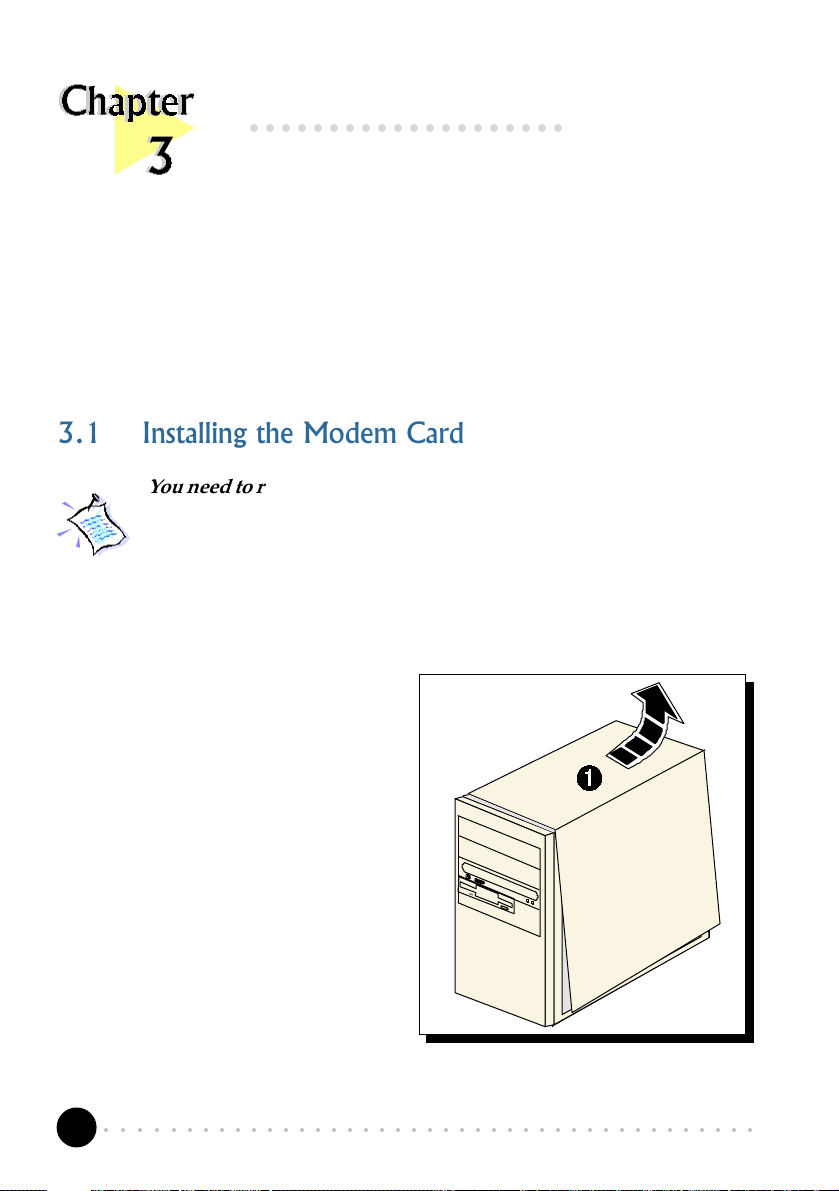
3.1 Installing the Modem Card
You need to remove any existing modem installed in your computer.
If your modem is non Plug-and-Play, you need to un-install its
modem drivers before you remove it. Check your existing modem
documentation for details on this.
Power off your computer and any connected devices before installing
your modem!
telephone line to your computer.
¶ Remove the cover of your
computer.
○○○○○○○○○○○○○○○○○○○○○○○○○○○○○○○○○○○○○○○○○
10
Page 11
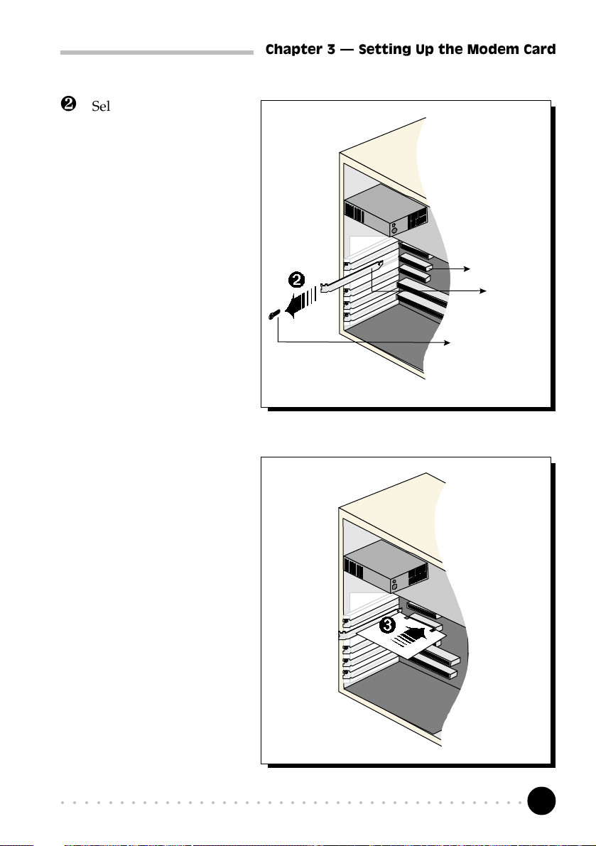
· Select an available PCI
Bus slot and remove its
cover plate. Keep the
mounting screw to
secure your card later.
Chapter 3 Setting Up the Modem Card
PCI Bus Slot
Cover Plate
Mounting Screw
¸ Align your card with
the selected PCI Bus
slot and firmly push it
into the slot. If the card
does not slide in, do
not force it. Make sure
that the card is lined up
properly and try again.
○○○○○○○○○○○○○○○○○○○○○○○○○○○○○○○○○○○○○○○○○
11
Page 12
Chapter 3 Setting Up the Modem Card
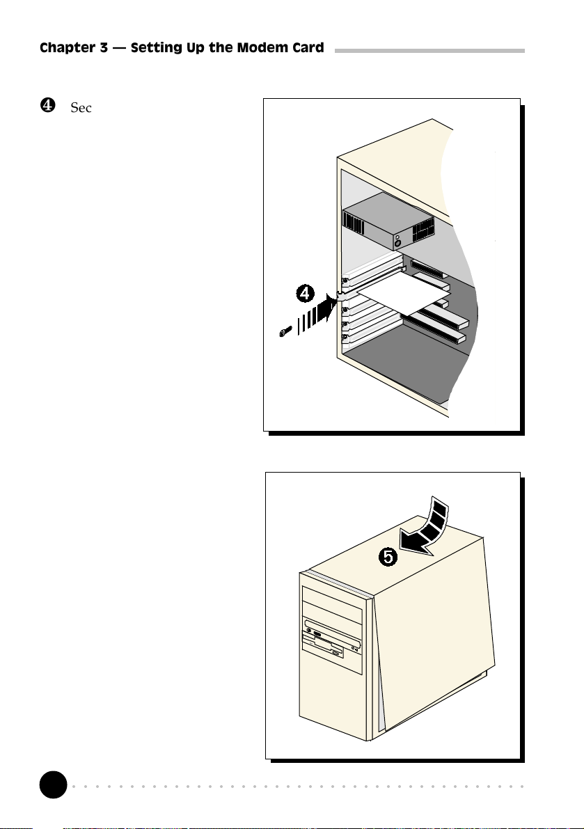
¹ Secure your card to your
computer chassis with the
mounting screw.
For MSP3880V-W/SP-W users:
You may use a TAD cable to
internally connect the modem
card and your compatible
sound card. With this
connection, all devices (e.g.
microphone, speakers) are to be
connected to your sound card
for voice recording and
speakerphone. Refer to
Appendix D - TAD Connection of
this Users Manual for details.
º Replace the cover of your
computer.
○○○○○○○○○○○○○○○○○○○○○○○○○○○○○○○○○○○○○○○○○
12
Page 13
Chapter 3 Setting Up the Modem Card
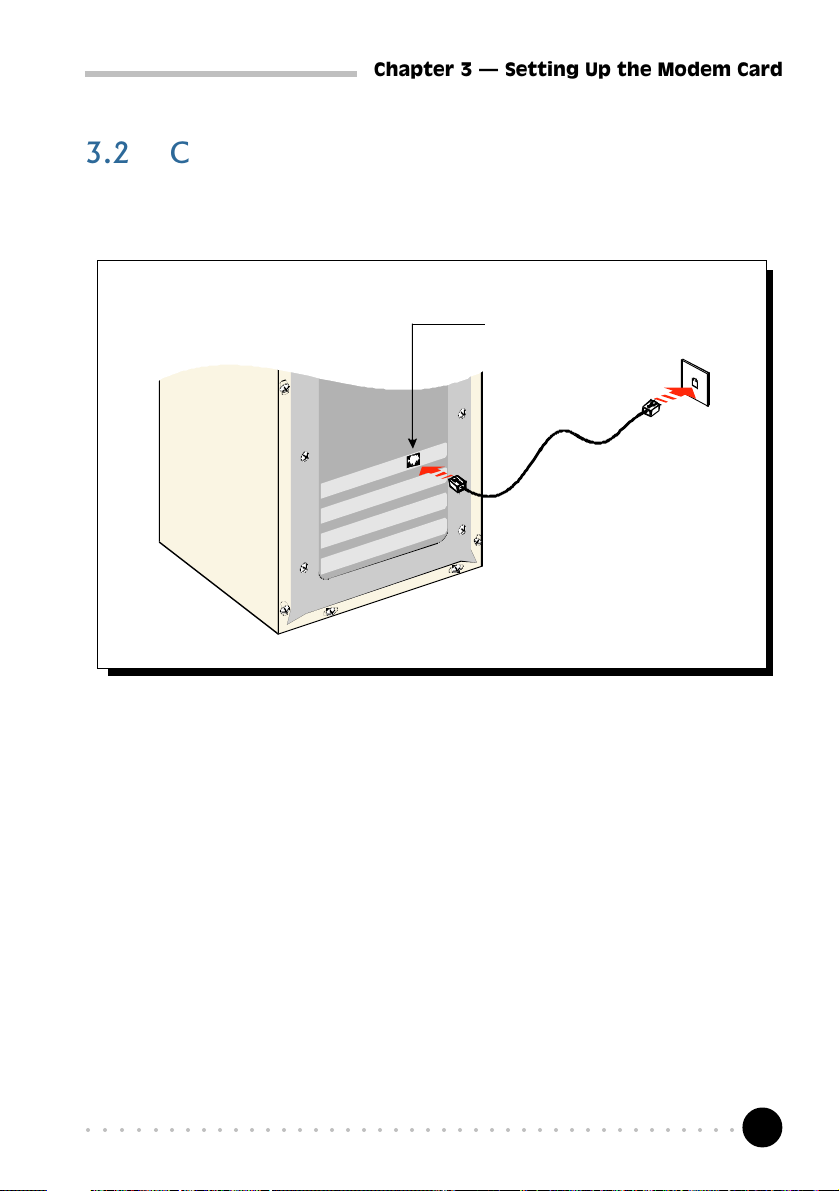
3.2 Connecting the Modem Card
3.2.1 For MSP3880-W users
LINE – to Telephone
Wall Socket
Telephone
Wall Socket
¶ Connect one end of the telephone extension cord to the modem card and
the other end to the telephone wall socket.
This completes the setting up of your modem. Please proceed to the next chapter
to install your modem drivers.
○○○○○○○○○○○○○○○○○○○○○○○○○○○○○○○○○○○○○○○○○
13
Page 14

Chapter 3 Setting Up the Modem Card
3.2.2 For MSP3880SP-W/V-W users
MIC IN – to Microphone
LINE-OUT
†
Available on MSP3880SP-W
†
†
Audio cable
LINE – to
Telephone Wall
Socket
Telephone
extension
cord
Telephone
Wall Socket
Microphone
Speakers,
Headphone
or Sound
card
¶ Connect one end of the telephone extension cord to the modem card and
the other end to the telephone wall socket.
· Connect a microphone to your modem card.
(This optional connection allows you to speak over the microphone during
speakerphone conversations)
¸ Connect your active speakers/headphone to your modem card.
This connection is required to receive sound output from your modem card. Before
you make use of this LINE-OUT jack, you need to run the Set Audio Output Utility
to configure your modems sound output from Buzzer to Line-Out option.
i) From the Windows taskbar, click Start > Run.
ii) In the text box, type C:\Windows\setaudio.exe. Click OK.
○○○○○○○○○○○○○○○○○○○○○○○○○○○○○○○○○○○○○○○○○
14
Page 15

Chapter 3 Setting Up the Modem Card
iii) From the dialog prompt, select Line-Out.
To configure back to buzzer, run the same utility again and click the Buzzer option.
º Alternatively, if you have a sound card (with speakers attached), you may
want to externally connect an audio cable from this LINE-OUT jack of
your modem card to the LINE-IN jack of your sound card.
This connection is required if you want to do voice playback.
For voice recording, the microphone must be connected to the MIC-IN
Jack of your compatible sound card.
Instead of using the audio cable, you may also use a TAD cable to
internally connect your modem card and your compatible sound card
as described in Appendix D - TAD Connection. For this connection,
all devices (e.g. microphone, speakers) are to be connected to your
sound card, regardless of voice recording or speakerphone.
This completes the setting up of your modem. Please proceed to the next chapter
to install your modem drivers.
○○○○○○○○○○○○○○○○○○○○○○○○○○○○○○○○○○○○○○○○○
15
Page 16

○○○○○○○○○○○○○○○○○○○○
Installing the Modem Drivers
This chapter contains information on how to install the modem drivers under
Windows® 95/98 and Windows NT® 4.0.
4.1 For Windows® 95
(The following screen shots are based on the MSP3880SP-W card)
Power on your computer to start Windows® 95. Windows® 95 will detect the
newly installed modem and an Update Device Driver Wizard window will
appear.
1
Place your Installation CD into your
CD-ROM drive.
Click Next.
○○○○○○○○○○○○○○○○○○○○○○○○○○○○○○○○○○○○○○○○○
16
Page 17

Chapter 4 Installing the Modem Drivers
Windows® 95 will now prompt you that the modem drivers have been found.
2
Click Finish to
continue with the
installation.
When system
prompts for the
Installation CD,
click OK.
3
○○○○○○○○○○○○○○○○○○○○○○○○○○○○○○○○○○○○○○○○○
17
Page 18

Chapter 4 Installing the Modem Drivers
The Copying Files... window will appear.
4
Type D:\ in the text box
(if D is not the letter of
your CD-ROM drive,
substitute with the
appropriate letter) and
click OK.
Restart your system, if prompted.
This completes the installation of the modem drivers in Windows® 95. Proceed
to the next chapter to test your modem.
○○○○○○○○○○○○○○○○○○○○○○○○○○○○○○○○○○○○○○○○○
18
Page 19

Chapter 4 Installing the Modem Drivers
4.2 For Windows® 98
(The following screen shots are based on the MSP3880SP-W card)
Power on your computer to start Windows® 98. Windows® 98 will detect the
newly-installed modem and an Add New Hardware Wizard window will appear.
1
Place your Installation CD into
the CD-ROM drive.
Click Next.
The next window prompt will ask for your modem drivers.
2
Click the option Search for the
best driver for your device
(Recommended).
Click Next.
○○○○○○○○○○○○○○○○○○○○○○○○○○○○○○○○○○○○○○○○○
19
Page 20

Chapter 4 Installing the Modem Drivers
The following window will prompt for the source of your drivers.
Click the option CD-ROM drive.
Click Next.
Windows will prompt that it has located the driver.
3
Click Next to proceed with the
4
installation.
To complete the drivers installation, click Finish and restart your system, if
prompted.
This completes the installation of the modem drivers in Windows® 98. Proceed
to the next chapter to test your modem.
○○○○○○○○○○○○○○○○○○○○○○○○○○○○○○○○○○○○○○○○○
20
Page 21

Chapter 4 Installing the Modem Drivers
4.3 For Windows NT® 4.0
1. Start Windows NT®.
2. Place your Installation CD into the CD-ROM drive.
3. From the Windows taskbar, click Start > Run... .
4. In the Run text box, type "D:\Winnt40\*\setup.exe"
(Assuming your CD-ROM drive is D. If not, substitute drive letter accordingly)
* For users of MSP3880SP-W, type SP-W
For users of MSP3880V-W, type V- W
For users of MSP3880-W, type W
Click OK.
5. Click the Next button and select the Product Name from the Modem Board
Installation Wizard.
6. Follow any on-screen instructions to complete the software installation.
This completes the installation of the modem drivers in Windows NT® 4.0. Please
proceed to the next chapter to test your modem.
○○○○○○○○○○○○○○○○○○○○○○○○○○○○○○○○○○○○○○○○○
21
Page 22

○○○○○○○○○○○○○○○○○○○○
Testing the Modem Card & Setting the
Country
This chapter contains information on how to test your modem card in
Windows® 95/98 & Windows NT® 4.0.
The testing procedures and setting the country for MSP3880 W series
in Windows 95® and 98 are exactly the same. The following
illustrations are based on the model MSP3880SP-W, in the Windows
98 environment.
5.1 Windows® 95/98
5.1.1 Testing the modem
®
From the Windows taskbar, click
1
Start > Settings > Control Panel.
○○○○○○○○○○○○○○○○○○○○○○○○○○○○○○○○○○○○○○○○○
22
Page 23

Chapter 5 Testing the Modem Card
You will see the MSP3880 modem listed.
2
Double-click the Modems icon.
Click on the Diagnostics tab.
○○○○○○○○○○○○○○○○○○○○○○○○○○○○○○○○○○○○○○○○○
3
23
Page 24

Chapter 5 Testing the Modem Card
Select the COM Port that your
modem is connected to.
Click More Info...
4
(The Port Information shown
here may differ from what you
see on your computer. It is
determined by the COM Port
which you connect your
modem to)
The More Info... window
will appear, showing a list
of AT commands. This
indicates a successfully-
installed modem.
Click OK.
○○○○○○○○○○○○○○○○○○○○○○○○○○○○○○○○○○○○○○○○○
24
5
Page 25

Chapter 5 Testing the Modem Card
If your modem is not installed properly, the set of AT commands will not be
listed. You may also be prompted by an error message, stating that it was unable
to open the COM Port. If this happens, refer to the Appendix B - Troubleshooting
Guide While testing the modem, the system gave an error message stating
that it was unable to open the COM Port.
5.1.2 Setting the Country
If you are using the modem card outside the United Kingdom, ensure that the country
setting is correct for your location. In some cases, the country is set to match the
Operating System selected and re-selection is required to match your exact location. To
check the current setting, follow the steps:
1. From the desktop, right-click on the My Computer icon and select
Properties.
2. Click the Device Manager tab and double-click on Modem.
3. Select your product model and click Properties.
4. Click the Country Select tab. The current country setting used is marked
with an asterisk. Change it to the country that you are currently in if it is set
incorrectly.
○○○○○○○○○○○○○○○○○○○○○○○○○○○○○○○○○○○○○○○○○
25
Page 26

Chapter 5 Testing the Modem Card
5.2 Windows NT® 4.0
5.2.1 Testing the modem
1. From the Windows taskbar, click Start > Programs > Accessories >
HyperTerminal > HyperTerminal.
2. Key in the required information prompted by the dialog boxes.
3. Click OK after entering any telephone number in the dialog box.
4. At the next dialog prompt, click Cancel.
5. Type "AT" and press Enter. You should see a response, OK.
6. Your modem is now ready to run.
5.2.2 Setting the Country
1. From the Windows taskbar, click Start> Settings>Control Panel.
2. Double-click on the HSF Modem Country Select icon.
3. If the current country setting is incorrect, change it to the country that you
are currently in.
○○○○○○○○○○○○○○○○○○○○○○○○○○○○○○○○○○○○○○○○○
26
Page 27

○○○○○○○○○○○○○○○○○○○○
Deinstalling the Modem Card
From the Control Panel, double-click Add/Remove Programs. Select MSP3880-
W 56K Modem and then click the Add/Remove... button. Select MSP3880-W
56K Modem Files if it is in the list and then click the Add/Remove... button.
MSP3880-W, MSP3880V-W or MSP3880SP-W will be displayed depending on
the modem card installed.
○○○○○○○○○○○○○○○○○○○○○○○○○○○○○○○○○○○○○○○○○
27
Page 28

○○○○○○○○○○○○○○○○○○○
Frequently Asked Questions
This section provides the answers to some of the commonly
asked questions on your modem.
How do I identify MSP3880 modem and its driver version ?
The model of your card is printed on the serial number label located at the rear
of the modem card. To get the driver version, you can also issue an ATI3
command using any telephony Data terminal application.
What is V.90 ?
V.90 is a new standard approved by the International Telecommunication Union
for "56K" analog modems. It is a compromise officially reached between the
two competing standards - X2 (from 3COM/USR) and K56Flex (from
Rockwell/Lucent).
What resources does MSP3880 use ?
Depending on system, the resources used is either IRQ9, IRQ10 or IRQ11
for systems that have two COM ports. If the system has only one COM port,
IRQ3 may be used.
What is TAD ? (for MSP3880V-W/SP-W)
TAD stands for Telephone Answering Device. Most modems and sound cards
nowadays come with a built-in TAD connector. Reasons are as follow:
1. It establishes a link between the modem card and sound card internally.
○○○○○○○○○○○○○○○○○○○○○○○○○○○○○○○○○○○○○○○○○
28
Page 29

Appendix A Frequently Asked Questions
2. It allows user to leave the microphone connection on the sound card, while
the same microphone can be used during speakerphone conversation.
3. It allows user to leave the speakers connection on the sound card, while the
same speakers can be used for any modem audio output. (see ReadMe.txt
file for the Pin configurations)
What is speakerphone feature ? (for MSP3880SP-W)
During phone conversations, modem speakerphone feature allows you to speak
over the microphone and receives from the speakers.
How do I use the modem speakerphone ? (for MSP3880SP-W)
To use the speakerphone feature, make sure that you have installed, connected
and tested your card as described in Chapter 3, 4 and 5 respectively. Then
run the Communications Application bundled in your MSP3880 Installation
CD/Disk to use the speakerphone.
Do MSP3800V-W and MSP3880SP-W have full-duplex feature ?
Full duplex is the ability to record and playback audio at the same time.
MSP3800V-W and MSP3800SP-W are able to do this while maintaining full
16-bit 48KHz quality.
Will MSP3880 work on all motherboards?
Yes, if the motherboard has at least one free PCI slot and meets the minimum
system requirements.
What is the maximum speed that MSP3880 supports and whose
solution is this card using?
The MSP3880 modem supports up to 56kbps. It is also backward compatible
with most of the old standards. The MSP3880 uses Rockwell SoftK56 chipset
solution.
○○○○○○○○○○○○○○○○○○○○○○○○○○○○○○○○○○○○○○○○○
29
Page 30

Appendix A Frequently Asked Questions
Is this modem upgradable to ITU V.90 56k standard?
This is a V.90 ready modem. You may also visit our website to get the latest
updates on the release timing for the updated drivers.
Where can I get the updated driver for my modem?
You can visit our website for any updated drivers.
How to initialize the modem?
The following modem command is used to initialize the modem in the
terminal emulation mode such as in Windows® 95 Hyperterminal application.
AT&FE0V1S0=0&C1&D2+MR=2;+DR=1;+ER=1;W0
I do not have any application and needs to do some faxing. How do
I install fax in Windows® 98?
If you are in the US, go to directory
D:\Tools\oldwin95\message\us (in your Windows® 98 installation CD)
For other countries, go to
D:\Tools\oldwin95\message\intl (in your Windows® 98 installation
CD)
(Assuming your CD-ROM drive is D. Else substitute the drive letter accordingly)
i) Run wms.exe under the directory to install Microsoft Messaging.
ii) Next run awfax.exe under the same directory to install Microsoft Fax.
For further information on Microsoft Messaging and Microsoft Fax, read wms-
fax.txt (from the same directory) in your Windows® 98 CD.
What games does MSP3880 support?
It can support almost all PC titles.
○○○○○○○○○○○○○○○○○○○○○○○○○○○○○○○○○○○○○○○○○
30
Page 31

Appendix A Frequently Asked Questions
What do TAPI and Non-TAPI communication applications mean?
Generally, TAPI refers to true 32-bit communication applications. They do
not access the COM ports directly but through an Interface known as TAPI
system of Windows (Not Windows 3.1x).
Non-TAPI applications are also referred to as 16-bit communication
applications. They access the COM ports directly. Windows® 95/98 supports
both TAPI and Non-TAPI communication applications.
I am using my system with the card in another country. Is there any
settings that need to be changed ?
Yes. You need to ensure that the country setting for your modem card is
correct for your location. Carry out the following steps:
Windows 95/98
i) From the desktop, right-click on the My Computer icon and select
Properties.
ii) Click the Device Manager tab and double-click on Modem.
iii) Select your product model and click Properties.
iv) Click the Country Select tab. The current country setting is marked
with an asterisk. Change it to the country that you are currently in if it is
set incorrectly.
Windows NT4.0
i) From the Windows taskbar, click Start > Settings > Control Panel.
ii) Double-click on the HCF Modem Country Select icon.
iii) Select your current local country.
How do I know that my modem is V.90 ready ?
Windows 95/98
i) From the Windows taskbar, click Start > Settings > Control Panel.
ii) Double-click on the Modem icon.
○○○○○○○○○○○○○○○○○○○○○○○○○○○○○○○○○○○○○○○○○
31
Page 32

Appendix A Frequently Asked Questions
iii) Click the Diagnostic tab and select your product model.
iv) Click More Info... option and you will see ATI 3 displaying a string similar
as follow: SoftK56V90_V_B2.1_V2.07.01 (showing that the V.90 is
supported and ready).
Windows NT4.0
i) From Windows taskbar, click Start > Programs > Accessories >
HyperTerminal > HyperTermnial.
ii) Key in the required information prompted by the dialogue boxes.
iii) Click OK after entering any telephone number in the dialogue box.
iv) At the next dialogue box prompt, click Cancel.
v) Type ATI 3 and press Enter.
vi) You will see ATI 3 displaying a string similar as follow:
SoftK56V90_V_B2.1_V2.07.01 (showing that the V.90 is supported and
ready).
How do I see the resources listings ?
Windows 95/98
i) From the Windows taskbar, click Start > Settings > Control Panel.
ii) Double-click the Modems icon.
iii) Click the Diagnostics tab. Select your product model and click More
Info... option.
The IRQ (Interrupt) and memory range (Address) used by the modem will
be listed.
Windows NT4.0
Not applicable.
○○○○○○○○○○○○○○○○○○○○○○○○○○○○○○○○○○○○○○○○○
32
Page 33

Appendix A Frequently Asked Questions
Why is the default maximum speed in the Device Manager Properties
for MSP3880 showing 115200 ?
It is referring to the DTE speed which is the speed of data transfer between
Computer and Modem. This however will not have any effect on the maximum
speed for DCE, which is the speed of data transfer between Modem to ISP or
remote party.
○○○○○○○○○○○○○○○○○○○○○○○○○○○○○○○○○○○○○○○○○
33
Page 34

○○○○○○○○○○○○○○○○○○○
Troubleshooting Guide
This section provides a step-by-step solutions to problems
that you may encounter when using your modem.
This modem is set to V.90. But why am I getting slow connections to
my ISP ?
The majority of the telephone lines and ISP are already supporting V.90
connections. However, like all data connection, the connection is sensitive to
the amount of noise present in the phone line. Hence, only very "clean" phone
line can get high connection rate or throughput. You may want to check with
your telephone service provider.
The modem hangs up when an incoming call is received.
Disable the Call Waiting function for the Online Service, Internet Connection
and/or communications software you are using.
When I tried to dial out, the system gave me an error message "No
Dial Tone".
Check the Telephone Cable connection. If necessary, plug out and reconnect
the Telephone Cable. You may have other telephony application running. Please
use one telephony application at any one time.
There are incomprehensible characters appearing on the screen.
The data, parity and stop bit settings are incorrect. Try using the default
values or check with your ISP.
○○○○○○○○○○○○○○○○○○○○○○○○○○○○○○○○○○○○○○○○○
34
Page 35

Appendix B Troubleshooting
Why does my modem always connect at 33.6Kbps and not 56Kbps or
V.90 ?
Check with your Internet Service Provider (ISP) to ensure that they support
56Kbps or V.90 connections. You must also make sure that your card is using
the 56Kbps driver. For modems with Country Selection feature, please ensure
that the modem is set to your local country. To set the country select feature,
see Appendix A - "I am using my system with the card in another
country. Is there any setting that need to be changed ?"
My system does not detect the modem card when I boot up for the
first time.
Windows 95/98
Make sure that your card is fully inserted into the PCI Bus slot. However, if
you are sure that the card has been properly installed, do the following:
i) From the Windows taskbar, click Start > Settings > Control Panel.
ii) Double-click the System icon.
iii) Click the Device Manager tab.
iv) Check whether there is any yellow exclamation mark (error) on the Modem/
Sound, video and game controllers devices. If yes, select the device, click
Remove and OK. Re-install the drivers.
v) If the system still cannot detect the modem, you may wish to try using a
different PCI slot instead.
Windows NT4.0
Not applicable.
I have done a diagnostics test of my modem and there is nothing
wrong with it. However, when I use a communications software,
there seems to be an error. Why?
Try to use a different telephony application such as Microsoft Fax to fax a
document. If the sending of a fax is successful, then the fax function of your
modem is working fine.
○○○○○○○○○○○○○○○○○○○○○○○○○○○○○○○○○○○○○○○○○
35
Page 36

Appendix B Troubleshooting
Try to use Hyperterminal to dial up to a BBS. If the connection is successful,
then the data function of your modem is working fine. Try exiting the
communications software and running it again.
You may try to install new version of communication software that supports
higher interrupts.
I have done the Diagnostic test. However, the system gave an error
message that the system is unable to open the COM Port.
Windows 95/98
Make sure that you have closed all communication software (e.g. Hyperterminal,
Dial-up Networking, etc.) when you are doing the diagnostics test.
However, if there is no communications software running, do the following:
i) From the Windows taskbar, click Start > Settings > Control Panel.
ii) Double-click the System icon.
iii) Click the Device Manager tab.
iv) Check whether there is any yellow exclamation mark on the modem device.
If yes, remove the modem device and re-install the modem drivers.
Windows NT4.0
Not applicable.
Why isn't there any sound from the speakers ?
Go through the following steps:
i) Make sure that the connections from your speakers to your computer are
as described in the User Manual.
ii) If your speakers are active (amplified) speakers (with built in power supply
and amplifier), make sure that it is put to "ON". Passive speakers (without
built in power supply and amplifier) can only be used with an external
amplifier.
iii) Power from the Mains to your speakers are properly connected and powered
ON.
You should be able to hear audio output from your speakers now.
○○○○○○○○○○○○○○○○○○○○○○○○○○○○○○○○○○○○○○○○○
36
Page 37

○○○○○○○○○○○○○○○○○○○
Technical Specifications
This chapter contains the technical specifications of your card. The information may be
more useful for technically inclined users.
Modem Standards
V.90, K56Flex
V.34+, V.34, V.32bis, V.32, V.22bis, V.22, V.21
Bell 212A, Bell 103
Modem Data Rates
56Kbps (download speed from Internet Service Provider)
33.6Kbps 300bps
Data Throughput
Up to 115.2Kbps (with compression) and 57.6Kbps (without compression)
Error Correction
V.42 LAP-M and MNP2-4
Data Compression
V.42bis and MNP5
Fax Modulations
V.17, V.29, V.27ter, V21 Channel 2 Class 1 and Group 3 Protocol
○○○○○○○○○○○○○○○○○○○○○○○○○○○○○○○○○○○○○○○○○
37
Page 38

Appendix C Technical Specifications
H.324 Video Ready
V.80, V.8bis
Rockwell VRPI
PCI Interface
PCI 2.1 Interface
PCI Plug and Play
PCI Power Management (Wake-Up on Ring through PCI PME# support*)
* only if your system supports ACPI Power Management
The product specifications herein are subject to change without prior
notifications.
○○○○○○○○○○○○○○○○○○○○○○○○○○○○○○○○○○○○○○○○○
38
Page 39

TELEPHONE
WALL JACK
* MICROPHONE
* LINE-OUT
○○○○○○○○○○○○○○○○○○○○
TAD Connection
(for MSP3880SP-W/V-W models)
Modem TAD PIN Configuration
LINE-OUT to Sound C ard
PIN 1
Ground
PIN 2
Not Used
PIN 3
MIC-IN from Sound Card
PIN 4
Pin 1
Pin 1
TAD Cable
Wake-up ring
(Optional)
This is a "Wakeup
on Ring" connector for
use with systems that
support power management
function. This connector is
usually not used.
** TAD (on your modem card) TAD (on your sound card)
This is a Microphone input cum Line-Out
output connector for use with a compatible
sound card. When connected, it serves as
an audio communication channel between
the sound card and modem card
Compatible TAD connector on
the motherboard or sound card
Microphone or Speakers/headphones connections must be
connected at the SOUND CARD if you are using TAD connection
or an audio cable.
* Microphone and Line-out jacks are available on MSP3880SP-W only. When the
Line-Out of the modem is connected to the Line-In of the sound card with an
audio cable, it serves the same purpose as the TAD connection.
○○○○○○○○○○○○○○○○○○○○○○○○○○○○○○○○○○○○○○○○○
39
Page 40

Appendix D TAD Connection
** TAD connector is available on MSP3880V-W and MSP3880SP-W only. It serves
as an internal interfacing connection between the sound card and modem card.
It allows the microphone's and speakers' (Line-Out) connection to remain on the
sound card even if speakerphone conversation is used.
○○○○○○○○○○○○○○○○○○○○○○○○○○○○○○○○○○○○○○○○○
40
Page 41

○○○○○○○○○○○○○○○○○○○○
AT Commands
The following is the list of AT Commands you can see after successful installation of your
modem. The example used here is the MSP3880SP-W modem with a driver version of
V2.08.02.
ATI0 56000
ATI1 255
ATI2 OK
ATI3 SoftK56V90_V_B2.1_V2.08.02
ATI4 MSP3880SP-W 56K Modem
ATI5 180
ATI6 SoftK56
CModem Version 11
Rksample Version 340
ATI7 255
ATI8 Apr 26 1999 # 11:21:59
ATI9 UK
○○○○○○○○○○○○○○○○○○○○○○○○○○○○○○○○○○○○○○○○○
41
 Loading...