

Page 1
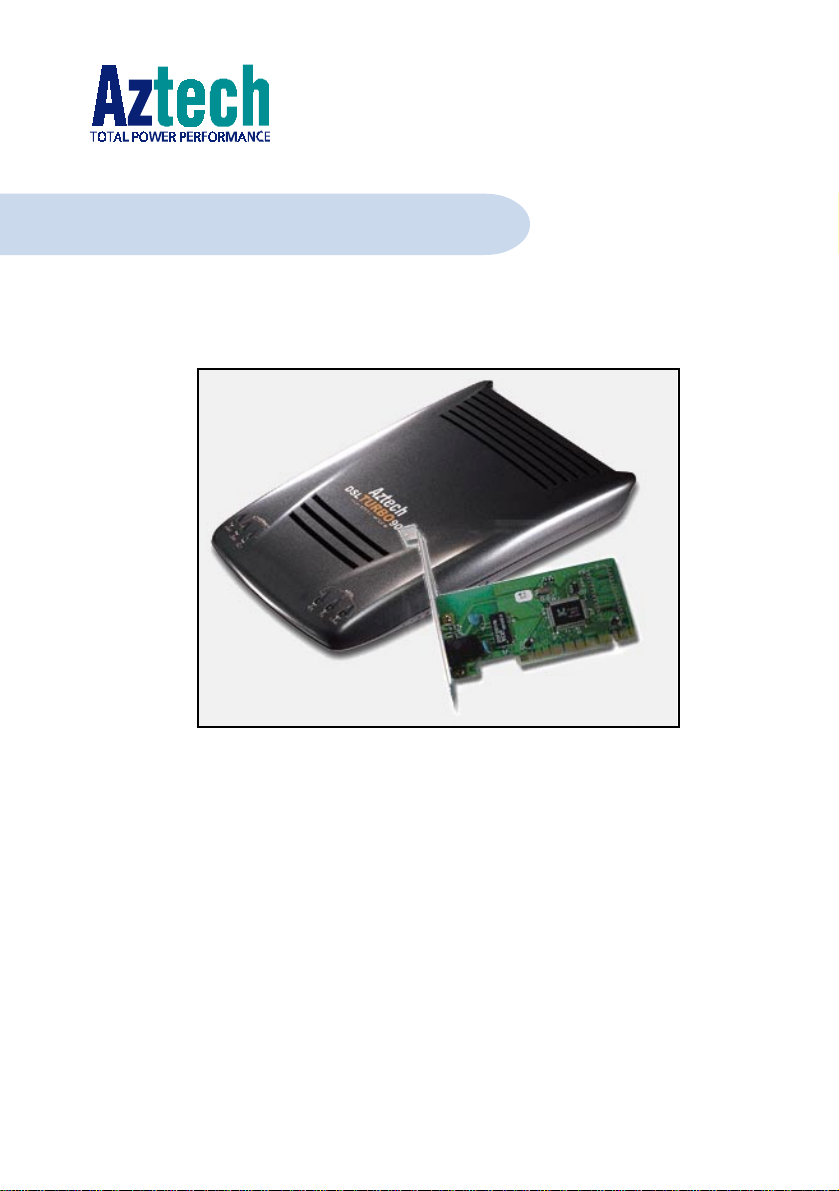
DSL TURBO 900 Package
Version 1.2
Ethernet ADSL High Speed Modem
with optional Ethernet Network Card
(Configured for Broadband Service)
Users Manual
Page 2

Page 3

Contents
Chapter 1 - Introducing DSL TURBO 900 Package.................................. 7
1.1 Overview ..................................................................................... 7
1.2 DSL TURBO 900 Features............................................................. 9
1.2.1 Front View ................................................................... 9
1.2.2 Rear View .................................................................... 10
Chapter 2 - Before You Begin ................................................................ 11
2.1 DSL TURBO 900 Package ............................................................. 11
2.2 Minimum System Requirements ..................................................... 12
2.3 Operating Environment .................................................................. 12
2.3.1 Temperature ................................................................ 12
2.3.2 Humidity ..................................................................... 12
2.4 Safety Precaution .......................................................................... 13
2.4.1 For NC2100(Lite) NetCard - optional ............................. 13
2.4.2 For DSL TURBO 900 .................................................... 13
2.5 Installation Notes ......................................................................... 13
Chapter 3 - Setting Up NC2100(Lite) NetCard ........................................ 14
3.1 Installing NC2100(Lite) NetCard .................................................... 14
3.2 Installing NC2100(Lite) NetCard Driver........................................... 17
3.2.1 Installing NC2100(Lite) NetCard Driver -
For Windows® Me ........................................................ 17
3.2.2 Installing NC2100(Lite) NetCard Driver -
For Windows® 98 / 98 Second Edition........................... 19
3.2.3 Installing NC2100(Lite) NetCard Driver -
For Windows® 95 OSR2 (Windows® 95B) ..................... 21
3.2.4 Installing NC2100(Lite) NetCard Driver - ....................... 23
For Windows® 95 OSR1 (Windows® 95A) / Windows® 95 ... 23
3.2.5 Installing NC2100(Lite) NetCard Driver -
For Windows® 2000 .................................................... 25
3.3 Verifying NC2100(Lite) NetCard ..................................................... 28
3.3.1 Verifying Your NC2100(Lite) NetCard - For Windows® Me,
98 Second Edition, 98, 95 OSR2, 95OSR1, 95 .............. 28
Page 4

3.3.2 Verifying Your NC2100(Lite) NetCard -
For Windows® 2000 .................................................... 31
3.3.3 LEDs Description .......................................................... 31
Chapter 4 - Setting Up DSL TURBO 900................................................ 32
4.1 Setup Overview ............................................................................ 32
4.2 Connecting DSL TURBO 900 ......................................................... 33
4.2.1 Connecting the UTP Ethernet Cable ............................... 33
4.2.2 Connecting the Telephone cable (RJ-11) ........................ 34
4.2.3 Connecting to a Telephone Set ...................................... 34
4.2.4 Connecting to The Mains ............................................... 35
4.3 Verifying Your Connections ............................................................. 36
4.3.1 Power LED (PWR) ........................................................ 36
4.3.2 Ethernet Link LED (LINK) .............................................. 36
4.3.3 ADSL Status LED (LINK) ............................................... 37
4.3.4 Phone connection ......................................................... 37
Chapter 5 - Installing WinPoET Dialer & DSLTEST .................................. 38
Chapter 6 - Configuring Your Network Card (optional) .............................. 42
Chapter 7 - Connecting to the Internet ................................................... 44
7.1 Establishing the Connection for Broadband Service ........................... 44
7.2 Ready to Go! ................................................................................ 45
7.2.1 Checking the Session Connection time ........................... 45
7.2.2 Disconnecting from the Internet .................................... 45
Chapter 8 - Uninstalling WinPoET Dialer & DSLTEST............................... 46
Page 5

Appendix A - Technical Specifications .................................................... 47
A.1 For NC2100(Lite) NetCard ............................................................ 47
A.1.1 Main Features .............................................................. 47
A.1.2 Technical Data ............................................................. 47
A.1.3 Network Operating System ............................................ 47
A.1.4 Electrical ..................................................................... 48
A.1.5 Connector and Sockets ................................................. 48
A.1.6 LED ............................................................................. 48
A.2 For DSL TURBO 900 .................................................................... 49
A.2.1 Main Features .............................................................. 49
A.2.2 ADSL Software Suppor t ................................................ 50
A.2.3 Platform Support.......................................................... 50
A.2.4 External Connectors ...................................................... 51
A.2.5 LED Indicators.............................................................. 51
A.2.6 Environmental .............................................................. 51
A.2.7 System Requirements ................................................... 51
Appendix B -Frequently Asked Questions ................................................ 52
Appendix C -Troubleshooting Guide ........................................................ 55
Appendix D -Technical Support .............................................................. 59
D.1 Aztech Sales Enquiries .................................................................. 59
D.2 Aztech Technical Support .............................................................. 59
D.3 Technical Support Considerations ................................................... 59
Page 6

Product warranty does not apply to damage caused by lightning, power surges or wrong voltage usage.
Page 7
Chapter 1
Introducing DSL
TURBO 900 Package
This section gives a brief introduction of DSL TURBO 900 and the
1.1 Overview
Congratulations on your purchase of DSL TURBO 900 ADSL Bridge Modem! This manual
covers the setup information for both your DSL TURBO 900 and NC2100(Lite) 10/100
base-T Network Interface Card - NC2100(Lite) NetCard.
NC2100(Lite) NetCard is an optional item in your package. It is a 10/100Mbps Fast
Ethernet Adapter that gives the flexibility to connect 10Mbps Ethernet or 100Mbps Fast
Ethernet without the need of tedious configurations. The support of the full duplex function
allows simultaneous transmission and reception on the twisted-pair link to a full duplex
Ethernet switching hub.
DSL TURBO 900 uses the latest communication technology, ADSL (Asymmetric Digital
Subscriber Line) that offers faster and uninterrupted Internet access. It allows use of real-
time, interactive multimedia and broadcast-quality for services such as video-on-demand,
collaborative computing and distance learning.
DSL TURBO 900 is capable of data rate in both Full-Rate and G.Lite, with Full Rate
transmission at up to 8 Mbps downstream, 640 Kbps upstream
at up to 1.5 Mbps downstream, 512 Kbps upstream
ADSL Protocols Support
To ensure the broadest customer reach, DSL TURBO 900 features multiple data encapsulation
formats for DSL transport over ATM PVCs, including the widely supported ADSL protocol
RFC 1483 (Ethernet Over ATM).
optional NC2100(Lite) Network Card.
1
1
. Major features include the following:
and G.Lite transmission
1 The actual downstream and upstream rates will depend on the service package offered by your ADSL
Service Provider.
○○○○○○○○○○○○○○○○○○○○○○○○○○○○○○○○○○○○○○○○○
7
Page 8
1. Introducing DSL TURBO 900 Package
Compatibility (Interoperability)
Multimode ADSL support: ANSI T1.143 Issue 2, ITU-T G.992.1 (G.dmt) and G.992.2
(G.Lite). DSL TURBO 900 uses discrete Multi-tone (DMT) line encoding scheme which is
also used by major ADSL equipment manufacturers, thus further guarantees interoperability
with network service providers worldwide.
○○○○○○○○○○○○○○○○○○○○○○○○○○○○○○○○○○○○○○○○○
8
Page 9
1. Introducing DSL TURBO 900 Package
1.2 DSL TURBO 900 Features
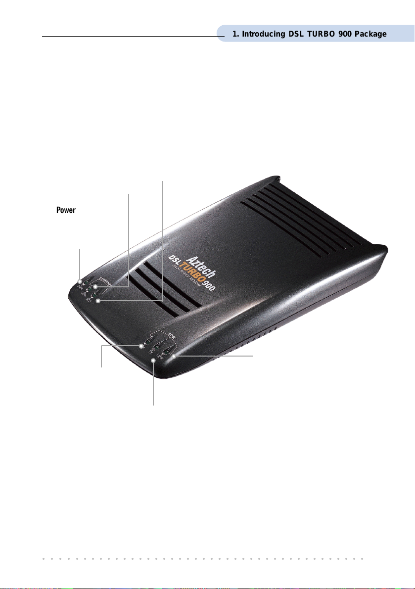
1.2.1 Front View
Ethernet Activity LED (ACT)
Ethernet Link LED (LINK)
Lights up when the Ethernet
link is established.
Power LED (PWR)
Lights up when
Power switch is
pressed ON.
Lights up when the Ethernet is
transmitting/receiving data.
ADSL Status LED (LINK)
Lights up when the ADSL Line is
ADSL Receive LED (RX)
Lights up when the
ADSL Line is
receiving data.
established.
ADSL Transmits LED (TX)
Lights up when the ADSL
Line is transmitting data.
○○○○○○○○○○○○○○○○○○○○○○○○○○○○○○○○○○○○○○○○○
9
Page 10
1. Introducing DSL TURBO 900 Package
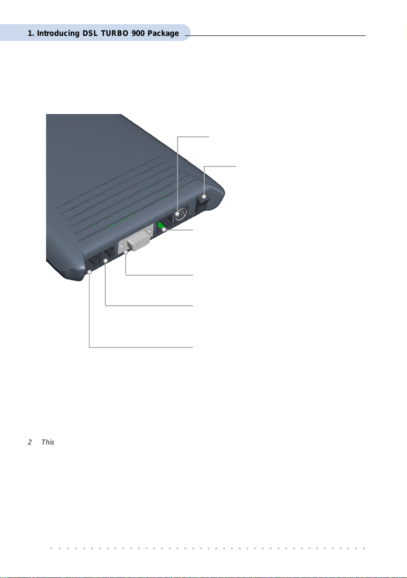
1.2.2 Rear View
Power Connector (DC IN)
To connect to your Mains supply
Power Switch (PWR)
To power on or off the modem.
I - indicates ON position
O - indicates OFF position
Ethernet Jack (ETHERNET)
10Base-T Ethernet jack (RJ-45) to
connect to your Ethernet card or Hub.
Serial Port (SERIAL)
9-pin serial port for local network management.
Line Jack (LINE)
Telephone jack (RJ-11) to connect to the
ADSL Line.
Phone Jack 2 (TEL)
Telephone jack (RJ-11) to connect to the
Telephone Handset.
2 This optional connection provides easy access to your Telephone set while working near the modem.
○○○○○○○○○○○○○○○○○○○○○○○○○○○○○○○○○○○○○○○○○
10
Page 11
Chapter 2
Before You Begin
This chapter contains information that you need to know before
setting up your DSL TURBO 900 package. It is important that
you go through them.
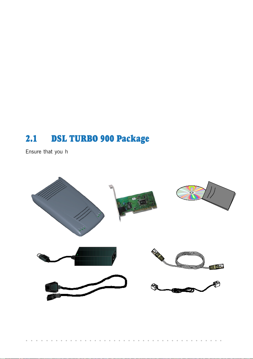
2.1 DSL TURBO 900 Package
Ensure that you have the following items in your package. For any missing item, please
contact your dealer immediately.
DSL TURBO 900
NC2100(Lite) NetCard
(optional)
Power adapter
Power cable
○○○○○○○○○○○○○○○○○○○○○○○○○○○○○○○○○○○○○○○○○
DSL TURBO 900 CD-ROM
DSL TURBO 900 Package
Users Manual
UTP Category 5 Crossover
Ethernet cable (RJ-45)
Telephone cable (RJ-11)
11
Page 12
2. Before You Begin
2.2 Minimum System Requirements
3
Make sure that your computer meets the following requirements before you start your
installation.
Pentium MMX 233MHz or equivalent
30MB free hard disk space
4
for system files and modem driver
(Windows CD-ROM may be required during installation, depending on your system
configurations.)
Operating System: Windows
®
95 / 98 / 98 Second Edition / Me / 2000
2.3 Operating Environment
For optimum performance, ensure that DSL TURBO 900 operates within the following
operating environment.
2.3.1 Temperature
Operating : 10o to 45 o Celsius
Non-Operating : -25
2.3.2 Humidity
o
50
to 113 o Fahrenheit
o
to 70 o Celsius
o
-13
to 158 o Fahrenheit
Operating : 30% to 80% Relative Humidity (Non-Condensing)
Non-Operating : 10% to 95% Relative Humidity (Non-Condensing)
3 The information listed are minimum system requirements needed to install your ADSL modem. Please
check and ensure that your system also meets the minimum system requirements set by the Internet
Service Provider (ISP) you subscribed to. Your system should meet the higher requirements of the two.
4 Additional free hard disk space may be required for your Internet Service Provider (ISP) installation
program and browser installation. Please check with your ISP.
○○○○○○○○○○○○○○○○○○○○○○○○○○○○○○○○○○○○○○○○○
12
Page 13
2. Before You Begin
2.4 Safety Precaution
2.4.1 For NC2100(Lite) NetCard - optional
• Do not remove your card from its protective bag until you are ready to install it.
• Always try to hold your card by its edges. Avoid touching any electronic components
on your card.
• Static electricity can cause permanent damage to your card. To prevent such a
damage, you must ground yourself during the installation:
» Use a grounding strap - a coiled wire with a clip at one end and an elastic strap
at the other. Wear the strap around your wrist and attach the clip to any non-
painted metal surface of your computer chassis.
» If you do not have a grounding strap, touch any non-painted surface of your
computer chassis before you begin installation, and again every minute or so
until the installation is completed.
2.4.2 For DSL TURBO 900
• Switch off the modem and adapter when the modem is not in use.
• During times of lightning/thunderstorms, do not use the modem.
• Keep the modem away from water and direct sunlight.
• Do not introduce any foreign material to the modem through the ventilation slits (e.g.
by dropping foreign items or poking into the slits).
2.5 Installation Notes
• The graphics and screens illustrations shown in this manual may differ from what you
see in your system, but the steps still apply.
• A Philips screwdriver is required for installation of your Network Card.
• The documentation for your computer should come in handy during the Network Card
installation. Have it ready by your side.
○○○○○○○○○○○○○○○○○○○○○○○○○○○○○○○○○○○○○○○○○
13
Page 14
Chapter 3
NC2100(Lite) NetCard
This chapter contains information on installing your NetCard and
its driver. Verification steps are also included to ensure correct
This chapter provides setting up procedures for the optional NC2100(Lite)
NetCard. If you have purchased a different model of Network Card, please
follow the installation instructions that comes with the card. Upon successful
installation, please proceed to Chapter 4 - Setting Up DSL TURBO 900.
Power off your computer and any connected devices before installing
your card !
Setting Up
installation.
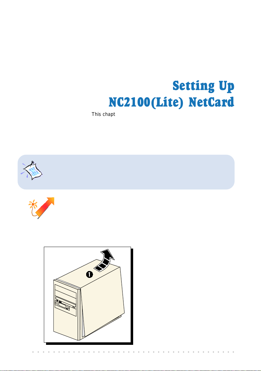
3.1 Installing NC2100(Lite) NetCard
Ê Remove the cover of your
computer.
○○○○○○○○○○○○○○○○○○○○○○○○○○○○○○○○○○○○○○○○○
14
Page 15
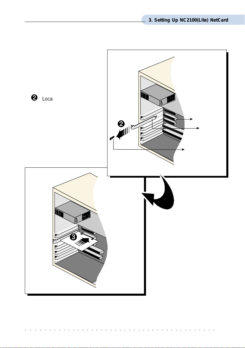
Ë Locate an available PCI-
Bus slot and remove its
cover plate, if required.
Keep the mounting screw to
secure your card later.
3. Setting Up NC2100(Lite) NetCard
PCI-Bus Slot
Cover Plate
Mounting Screw
Ì Align your card with the
PCI-Bus slot and firmly
push it into the slot.
If the card does not slide
in, do not force it. Make
sure that the card is
aligned properly and try
again.
○○○○○○○○○○○○○○○○○○○○○○○○○○○○○○○○○○○○○○○○○
15
Page 16
3. Setting Up NC2100(Lite) NetCard
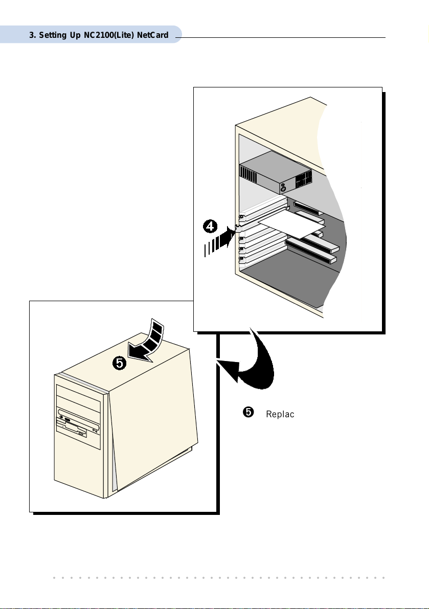
Í Secure your card to your
computer chassis with the
mounting screw.
Î Replace the cover of your
computer.
This completes the NC2100(Lite) NetCard installation. Please proceed to install the
NetCard driver.
○○○○○○○○○○○○○○○○○○○○○○○○○○○○○○○○○○○○○○○○○
16
Page 17
3. Setting Up NC2100(Lite) NetCard
3.2 Installing NC2100(Lite) NetCard Driver
This section contains the driver installation for Windows® Me, 98 Second Edition, 98, 95
OSR2, 95 OSR1, 95 and Windows
The screen shots and screens information illustrated in this manual serve
only as a guide. The exact information or procedures you see on your
system may vary, depending on your system configurations. For any
dissimilarities, follow closely to the instructions as prompted on your PC
screen !
®
2000.
3.2.1 Installing NC2100(Lite) NetCard Driver -
®
For Windows
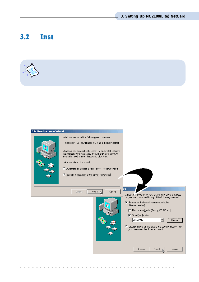
1. Start your Windows. Windows will detect your newly-installed network card and
prompt for its driver.
Me
Place the DSL 900E(B)
CD-ROM into your CD-
ROM Drive. Select
Specify the location of the
driver (Advanced) and
click Next.
2. Select Specify a location.
Click Browse and navigate to the
directory \WinMe on your
CD-ROM and click Next.
○○○○○○○○○○○○○○○○○○○○○○○○○○○○○○○○○○○○○○○○○
17
Page 18
3. Setting Up NC2100(Lite) NetCard
4. At the next prompt,
click Next again.
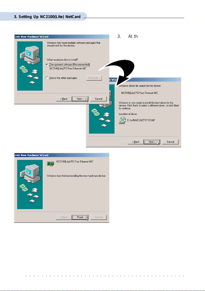
3. At the next prompt, select
The updated software
(Recommended) and click
Next.
5. Click Finish to complete the
installation.
6. At the prompt for restart, click Ye s .
This completes the driver installation for your NC2100(Lite) NetCard. Please proceed to
section 3.3 - Verifying NC2100(Lite) NetCard.
○○○○○○○○○○○○○○○○○○○○○○○○○○○○○○○○○○○○○○○○○
18
Page 19
3. Setting Up NC2100(Lite) NetCard
3.2.2 Installing NC2100(Lite) NetCard Driver -
®
For Windows
During installation, system may prompt for your Windows 98 / 98 Second
Edition CD-ROM for some files. Have it ready by your side.
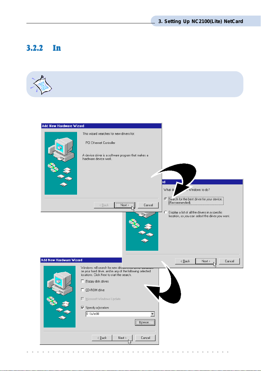
1. Start your Windows. Windows will detect your newly-installed network card and
prompt for its driver.
98 / 98 Second Edition
Place the DSL 900E(B)
CD-ROM into your CD-
ROM Drive and click Next.
2. At the next prompt, click the
option 'Search for the best
driver for your device.
(Recommended).' and click
Next.
3. Click 'Specify a
location'.
Click Browse and navigate
to \Win98 directory on
your CD-ROM and click
Next.
○○○○○○○○○○○○○○○○○○○○○○○○○○○○○○○○○○○○○○○○○
19
Page 20
3. Setting Up NC2100(Lite) NetCard
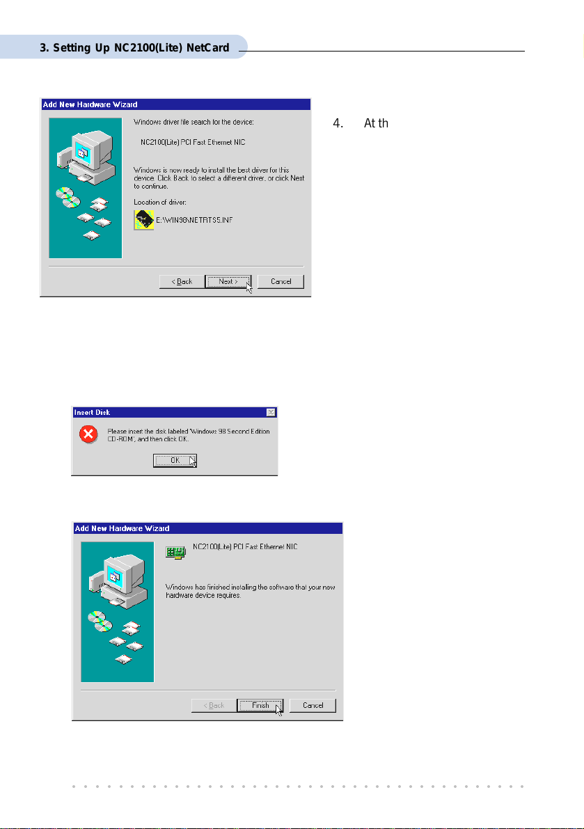
4. At the next prompt, click Next
again to proceed installation
with the specified driver.
5. Depending on your system configurations, system may prompt you for your Windows
98 / 98 Second Edition CD-ROM, .
Replace the DSL 900E(B) CD-ORM in your CD-ROM drive with your Windows 98 /
98 Second Edition CD-ROM and click OK. Windows will start copying the required
files.
(If you are prompted with a dialog box indicating
that files cannot be found, please direct it to
the location of your Windows 98 / 98 Second
Edition CD-ROM and click OK.)
6. Click Finish to complete the installation.
This completes the driver installation for your NC2100(Lite) NetCard. Please proceed to
section 3.3 - Verifying NC2100(Lite) NetCard.
○○○○○○○○○○○○○○○○○○○○○○○○○○○○○○○○○○○○○○○○○
20
Page 21

3. Setting Up NC2100(Lite) NetCard
3.2.3 Installing NC2100(Lite) NetCard Driver -
®
For Windows
During installation, system may prompt for your Windows 95 CD-ROM /
diskettes for some files. Have it ready by your side.
1. Start your Windows. Windows will detect your newly-installed network card and
prompt for its driver. Place the DSL 900E(B) CD-ROM into your CD-ROM Drive and
click Next.
95 OSR2 (Windows® 95B)
For Windows® 95x users, you need to have Microsoft Dial-Up Networking
(DUN), version 1.3 (or higher) installed in your system. If you already have it
installed in your system, please proceed with the following steps. Else, from the
Update Device Driver Wizard, click Cancel and proceed to install DUN first.
For DUN installation instructions, you may refer to the Frequently Asked
Questions,
‘How Do I Install Microsoft Dial-Up Networking (DUN)’
.
2. System will prompt for the location of your network card driver. Click Other
Locations... .
3. At the next prompt, click Browse and navigate to the \Win95 directory on your CD-
ROM and click OK.
○○○○○○○○○○○○○○○○○○○○○○○○○○○○○○○○○○○○○○○○○
21
Page 22

3. Setting Up NC2100(Lite) NetCard
4. Click Finish to proceed installation with the specified driver.
5. Upon system prompt for DSL 900E(B) CD-ROM, ensure that your CD-ROM is in your
CD-ROM drive and click OK.
(If you are prompted with dialog box indicating that files cannot be found, please direct it to
the location of your DSL 900E(B) CD-ROM and click OK.)
6. If you have not installed a network card in your system before, you may be prompted
with the some Network prompts.
i) At the prompt to provide computer and workgroup names, click OK.
ii) Enter the relevant information
and click Close.
7. Depending on your system configurations,
system may prompt you for your
Windows 95 CD-ROM or disketttes.
Replace the DSL 900E(B) CD-ROM in
your CD-ROM drive / Floppy disk drive
with your Windows 95 CD-ROM /
diskettes and click OK. Windows will
start copying the required files.
(If you are prompted with dialog box
indicating that files cannot be found, please
direct it to the location of your Windows 95
CD-ROM / diskettes and click OK.)
8. Restart your system when prompted.
This completes the driver installation for your NC2100(Lite) NetCard. Please proceed to
section 3.3 - Verifying NC2100(Lite) NetCard.
○○○○○○○○○○○○○○○○○○○○○○○○○○○○○○○○○○○○○○○○○
22
Page 23
3. Setting Up NC2100(Lite) NetCard
3.2.4 Installing NC2100(Lite) NetCard Driver -
®
For Windows
During installation, system may prompt for your Windows 95 CD-ROM /
diskettes for some files. Have it ready by your side.
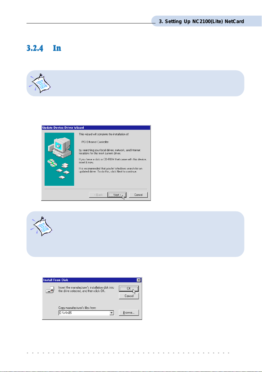
1. Power on your computer to start Windows. Windows will detect your newly-installed
Network Card and a New Hardware Found window will appear.
95 OSR1 (Windows® 95A) / Windows® 95
Select the option Driver from
disk provided by hardware
manufacturer.
Place your DSL 900E(B) CD-
ROM in your CD-ROM Drive
and click OK.
For Windows® 95x users, you need to have Microsoft Dial-Up Networking
(DUN), version 1.3 (or higher) installed in your system. If you already have it
installed in your system, please proceed with the following steps. Else, from the
Update Device Driver Wizard, click Cancel and proceed to install DUN first.
For DUN installation instructions, you may refer to the Frequently Asked
Questions,
‘How Do I Install Microsoft Dial-Up Networking (DUN)’
.
3. Click Browse and navigate to \Win95 directory on your CD-ROM and click OK.
○○○○○○○○○○○○○○○○○○○○○○○○○○○○○○○○○○○○○○○○○
23
Page 24

3. Setting Up NC2100(Lite) NetCard
4. If you have not installed a network card in your system before, you may be prompted
with the some Network prompts.
i) At the prompt to provide
computer and workgroup
names, click OK.
ii) Enter the relevant information
and click Close.
5. System may prompt you for your
Windows 95 CD-ROM or diskettes.
Replace the DSL 900E(B) CD-ROM in
your CD-ROM drive / Floppy disk drive
with your Windows 95 CD-ROM /
diskettes and click OK.
Windows will start copying the required
files.
(If you are prompted with dialog box
indicating file cannot be found, please direct
it to the location of your Windows 95 CD-
ROM / diskettes and click OK.)
6. Upon installation completes, Windows will prompt you to restart your system. Click
Ye s .
This completes the driver installation for your NC2100(Lite) NetCard. Please proceed to
section 3.3 - Verifying NC2100(Lite) NetCard.
○○○○○○○○○○○○○○○○○○○○○○○○○○○○○○○○○○○○○○○○○
24
Page 25

3. Setting Up NC2100(Lite) NetCard
3.2.5 Installing NC2100(Lite) NetCard Driver -
®
For Windows
1. Start your Windows. Upon detecting your newly-installed Network Card, Windows
will automatically install the Network Card driver that is pre-loaded in Windows®
2000.
Proceed with the following steps to update the installed Network Card driver.
2. From your Windows desktop, right-click on My Computer. Select Properties. Click
Hardware tab and click Device Manager... .
3. Double-click on Network adapters. You should see Realtek RTL8139(A)-based PCI
Fast Ethernet Adapter
2000
5
listed as shown.
Double-click on it. Select the
Driver tab and click Update
Driver... button.
4. From the Upgrade
Device Driver Wizard,
click Next.
5 Model name may differ slightly from what you see on your computer screen.
○○○○○○○○○○○○○○○○○○○○○○○○○○○○○○○○○○○○○○○○○
25
Page 26
3. Setting Up NC2100(Lite) NetCard
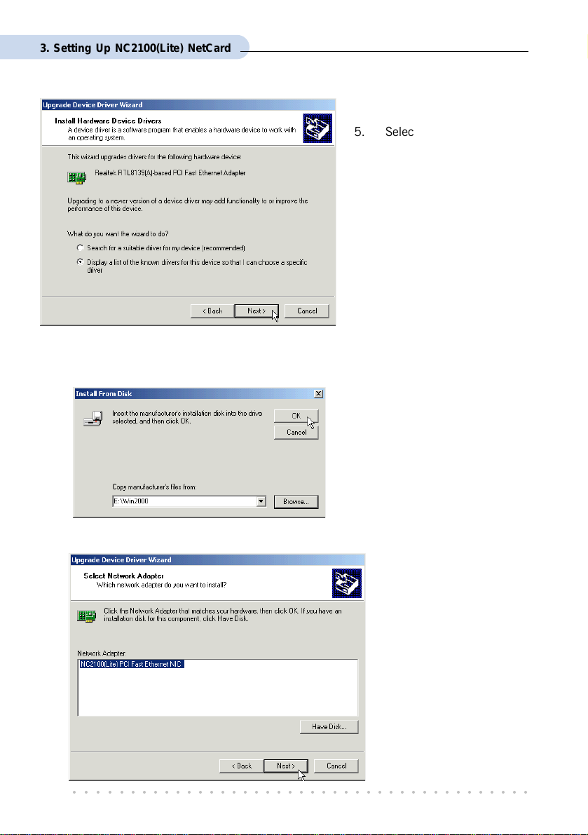
5. Select 'Display a list of
the known drivers for
this device so that I can
choose a specific driver'
and click Next.
6. At the next prompt, click Have Disk... .
7. Click Browse and navigate to \Win2000 directory on your CD-ROM and click OK.
8. At the next prompt, click N ext to proceed with the specified driver.
○○○○○○○○○○○○○○○○○○○○○○○○○○○○○○○○○○○○○○○○○
26
Page 27

3. Setting Up NC2100(Lite) NetCard
9. Click Next again.
10. You may be prompted with Digital Signature Not Found dialog box. This happens
when Windows is not able to detect a newer version of your driver.
Click Yes to proceed.
11. Click Finish to complete the installation process.
This completes the driver installation for your NC2100(Lite) NetCard. Please proceed to
section 3.3 - Verifying NC2100(Lite) NetCard.
○○○○○○○○○○○○○○○○○○○○○○○○○○○○○○○○○○○○○○○○○
27
Page 28

3. Setting Up NC2100(Lite) NetCard
3.3 Verifying NC2100(Lite) NetCard
This section contains information on how to verify your NC2100(Lite) NetCard in Windows
Me, 98 Second Edition, 98, 95 OSR2, 95 OSR1, 95 and Windows® 2000.
3.3.1 Verifying Your NC2100(Lite) NetCard
®
- For Windows
95 OSR1, 95
1. From your Windows desktop, right-click Network Neighborhood icon. Select Properties.
2. Select the Device Manager tab. Double-click on the Network adapters.
Me, 98 Second Edition, 98, 95 OSR2,
®
(If there is a yellow exclamation
mark on the network device,
select the device, click on
Remove and re-install your
NC2100(Lite) NetCard driver.)
You should see NC2100(Lite) PCI Fast Ethernet NIC listed as shown. This means
that your network card is installed successfully.
3. For Windows
- LEDs Description.
For Windows
if TCP/IP is installed in your system.
○○○○○○○○○○○○○○○○○○○○○○○○○○○○○○○○○○○○○○○○○
28
®
Me, 98 Second Edition and 98 users, please proceed to section 3.3.3
®
95 OSR2, 95 OSR1 and 95 users, proceed with the following to check
Page 29
3. Setting Up NC2100(Lite) NetCard
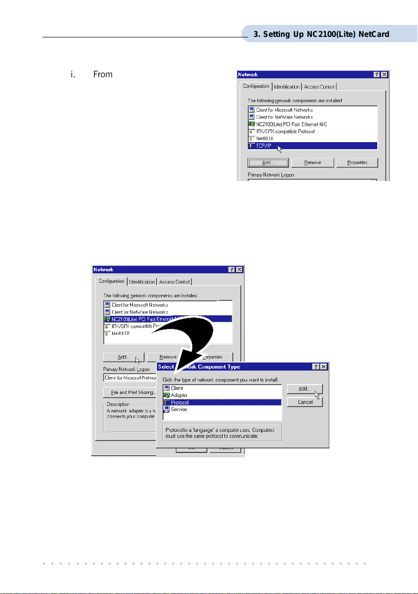
i. From your Windows desktop,
right-click on Network
Neighborhood icon. Select
Properties.
ii. From the Configuration tab,
check for TCP/IP listed (as
shown on your right).
If TCP/IP is listed, please proceed to section 3.3.3 - LEDs Description.
If your system is not installed with TCP/IP, please carry out the following
instructions:
iii. From the above step (ii), select NC2100(Lite) PCI Fast Ethernet NIC and click
Add.
iv. At the Select Network
Component Type prompt,
select Protocol and click
Add....
○○○○○○○○○○○○○○○○○○○○○○○○○○○○○○○○○○○○○○○○○
29
Page 30
3. Setting Up NC2100(Lite) NetCard
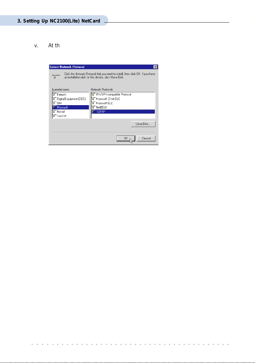
v. At the Manufacturers field, select Microsoft. At the Network Protocols field,
select TCP/IP. Click OK.
Click OK again.
vi. You will be prompted for your Windows 95 CD-ROM / diskettes. Place your
Windows 95 CD-ROM / diskettes in your CD-ROM Drive / Floppy disk drive
and click OK.
If you are prompted with DHCP prompt, asking if you want to see future DHCP messages,
click No. Restart your system when prompted.
Please proceed to section 3.3.3 - LEDs Description.
○○○○○○○○○○○○○○○○○○○○○○○○○○○○○○○○○○○○○○○○○
30
Page 31
3. Setting Up NC2100(Lite) NetCard
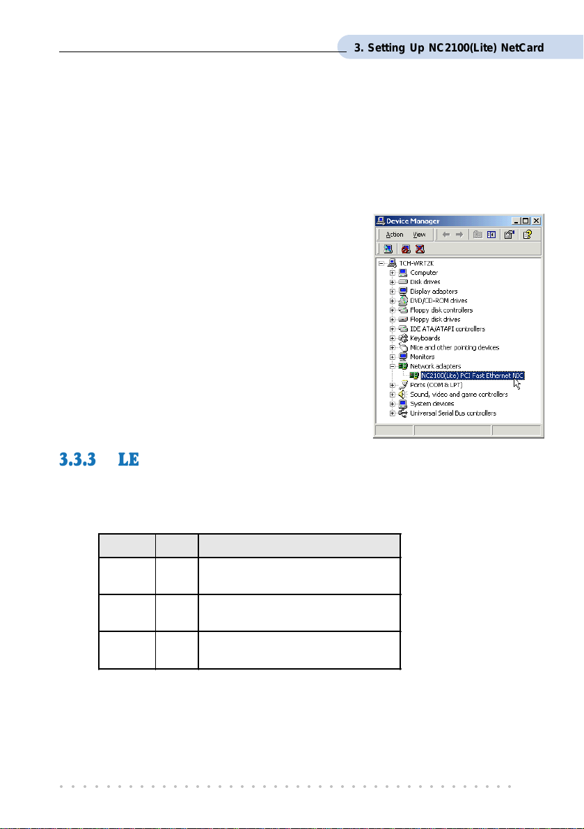
3.3.2 Verifying Your NC2100(Lite) NetCard
®
- For Windows
1. From your Windows desktop, right-click My Computer icon. Select Properties.
2. Select the Hardware tab and click Device Manager button.
Double-click on the Network adapters. You
should see NC2100(Lite) PCI Fast Ethernet
NIC listed. This means that your NC2100(Lite)
NetCard driver is successfully installed.
(If there is a yellow exclamation mark on the
network device, right-click on the device and
select Remove. Re-install your NC2100(Lite)
NetCard driver.)
Please proceed to section 3.3.3 - LEDs Description.
2000
3.3.3 LEDs Description
The following table explains the LEDs state for your NC2100(Lite) NetCard.
LEDs Light Description
Activity
Link
100M
ON
OFF
ON
OFF
ON
OFF
This completes the verification for your NC2100(Lite) NetCard. Please proceed to the next
chapter on Setting Up DSL TURBO 900.
○○○○○○○○○○○○○○○○○○○○○○○○○○○○○○○○○○○○○○○○○
transmission of data is in progress
no transmission of data
the link is g ood
there is no lin k
card is config ured at 100Mbps
card is config ured at 10Mbps
31
Page 32

Chapter 4
DSL TURBO 900
This chapter contains information on setting up DSL TURBO 900.
Verification steps are also included to ensure correct connections.
4.1 Setup Overview
The following gives an overview of the DSL TURBO 900 setup.
Setting Up
Telephone 1
Micro-Filter
LINE
6 The Micro-Filter can be purchased separately from your dealer.
○○○○○○○○○○○○○○○○○○○○○○○○○○○○○○○○○○○○○○○○○
32
6
LINE
10 Base-T
(UTP Crossover Ethernet cable
to NC2100(Lite) NetCard)
PC
Telephone 2
DSL TURBO 900
The Mains
Supply
Power adapter
For details on the usage of MicroFilter, please refer to Frequently
Asked Questions section, ‘
to use Micro-Filter when using
’.
ADSL?
Do I need
Page 33

4. Setting Up DSL TURBO 900
4.2 Connecting DSL TURBO 900
Please carry out the following steps to connect your modem to your computer.
Power off your computer and any connected devices before installing your
modem!
4.2.1 Connecting the UTP Ethernet Cable
Connect one end of the Ethernet cable to the ETHERNET jack on DSL TURBO 900 and
the other end to the Ethernet jack on NC2100(Lite) NetCard.
NC2100(Lite) NetCard
ETHERNET
Rear view of DSL
TURBO 900
○○○○○○○○○○○○○○○○○○○○○○○○○○○○○○○○○○○○○○○○○
Rear view of a PC
UTP Crossover
Ethernet cable
33
Page 34

4. Setting Up DSL TURBO 900
4.2.2 Connecting the Telephone cable (RJ-11)
Connect one end of the telephone cable to the LINE jack on DSL TURBO 900 and the other
end to your Telephone wall socket.
LINE
Telephone wall
socket
Telephone cable
Rear view of
DSL TURBO 900
4.2.3 Connecting to a Telephone Set
This connection is optional. The TEL jack provides easy access to your Telephone set while
working near DSL TURBO 900.
Connect the Phone cable to the TEL jack on DSL TURBO 900.
Telephone set
Rear view of
DSL TURBO 900
TEL
Phone cable
○○○○○○○○○○○○○○○○○○○○○○○○○○○○○○○○○○○○○○○○○
34
Page 35

4. Setting Up DSL TURBO 900
4.2.4 Connecting to The Mains
Connect the connector of the Power adapter to the DC IN on DSL TURBO 900.
Attach the jack of the Power cable to the Power adapter as shown, and the Power plug to
The Mains.
The Mains
DC IN
Power adapter
Power cable
Rear view of
DSL TURBO 900
○○○○○○○○○○○○○○○○○○○○○○○○○○○○○○○○○○○○○○○○○
35
Page 36
4. Setting Up DSL TURBO 900
4.3 Verifying Your Connections
To verify the connections that you have made for DSL TURBO 900,
Power on DSL TURBO 900:
i) On the Switch at The Mains, connected to the power adapter.
ii) On the Switch at the rear of DSL TURBO 900.
Observe the following LEDs on your modem:
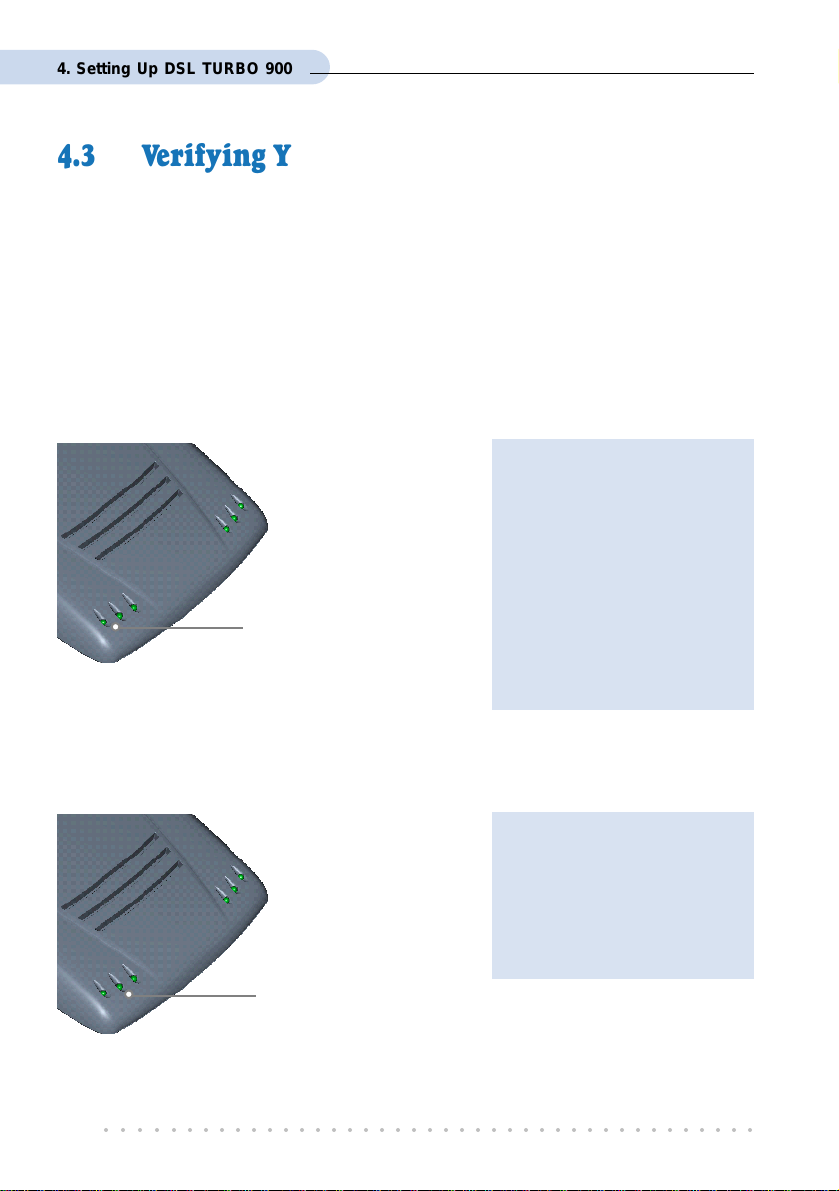
4.3.1 Power LED (PWR)
If your Power LED does not
light up, check that:
i) the Mains Supply is
powered on and the Power
switch on the modem is
at ‘ I’ position.
You should see this Power
LED lights up.
ii) the connection is carried
out as described in section
4.2.4 - Connecting to The
Mains.
4.3.2 Ethernet Link LED (LINK)
If your Ethernet Link LED does
not light up, check that:
i) the connection is carried
out as described in section
4.2.1 - Connecting the
UTP Ethernet Cable.
You should see this
Ethernet Link LED
lights up.
○○○○○○○○○○○○○○○○○○○○○○○○○○○○○○○○○○○○○○○○○
36
Page 37
4. Setting Up DSL TURBO 900
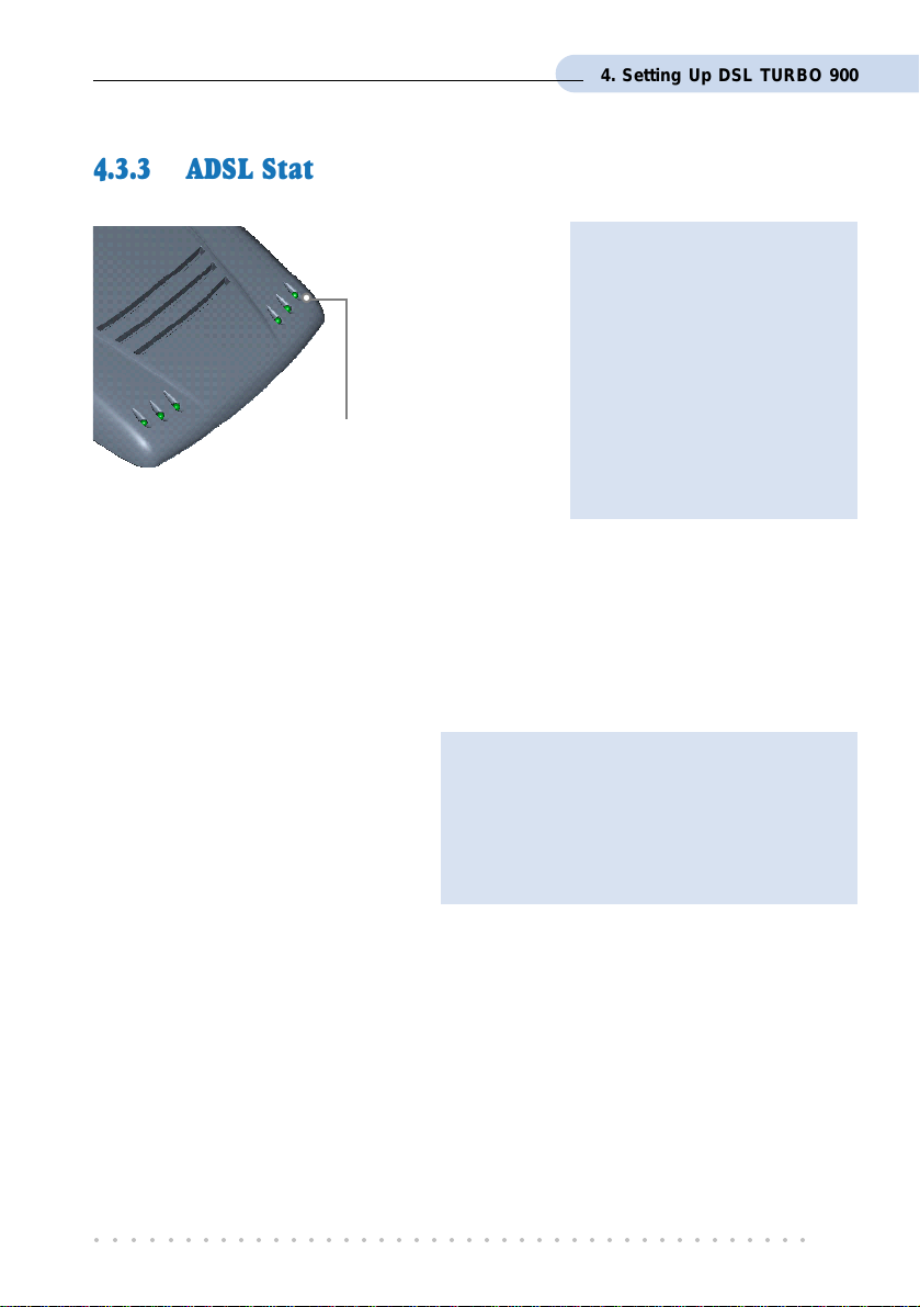
4.3.3 ADSL Status LED (LINK)
If your ADSL Status LED does
not light up, check that:
i) the Mains Supply is
powered on and the Power
switch on the modem is at
‘I’ position.
ii) the connection is carried
This LED will start blinking, trying
to establish a connection. Once
the connection is established, this
LED will remain lit.
If the mentioned 3 LEDs all light up, it means that your modem are successfully connected.
out as described in section
4.2.2 - Connecting the
Telephone cable (RJ-11).
4.3.4 Phone connection
If you have connected a Telephone
set to your modem, pick up the
handset of the Telephone. You should
hear the normal dial-tone.
This completes the verification on DSL TURBO 900 connections. Please proceed to the next
chapter to install both WinPoET Dialer (for dialing-up to Internet) and DSLTEST utility (for
testing the functionality of DSL TURBO 900).
○○○○○○○○○○○○○○○○○○○○○○○○○○○○○○○○○○○○○○○○○
If you do not hear the normal dial-tone of a
telephone, check that the connection is done
as described in section 4.2.3 - Connecting
to a Telephone Set. If your connections are
correct, it may be due to a faulty phone
cable that you are using.
37
Page 38
Chapter 5
Installing WinPoET Dialer
& DSLTEST
The installation procedures for Windows® 95, 98, 98 Second Edition, Me and
Window
98 Second Edition. For any dissimilarities, follow closely to the instructions
as prompted on your PC screen.
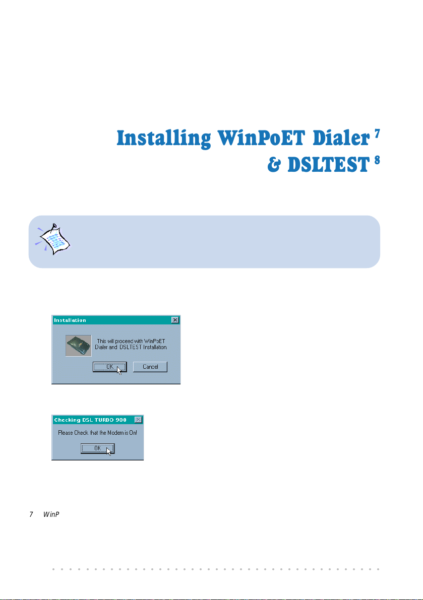
1. Place the DSL TURBO 900 CD-ROM in your CD-ROM drive. At the following prompt,
click OK.
2. Ensure that you have powered on DSL TURBO 900 before clicking OK at the prompt.
®
2000 are similar. The following installation is based on Windows
®
7
8
7 WinPoET is a dial-up client that allows you to connect to the Internet. (see Chapter 7 - Connecting to
the Internet for details)
8 DSLTEST is a diagnostic utility that allows you to test your Ethernet Card, DSL TURBO 900 and your
connection to the Internet. (see Appendix C - Troubleshooting Guide, ‘ I am not able to connect to
the Internet’ for details.)
○○○○○○○○○○○○○○○○○○○○○○○○○○○○○○○○○○○○○○○○○
38
Page 39

5. Installing WinPoET Dialer & DSLTEST
3. For Windows® 98 Second Edition users, Windows will prompt for your Windows CD-
ROM during WinPoET installation. Please have the CD-ROM by your side.
Click OK.
4. The setup program will commence. The following WinPoET Setup - Welcome window
will be prompted.
Click Next.
5. At the Software License Agreement prompt, click Accept to proceed.
○○○○○○○○○○○○○○○○○○○○○○○○○○○○○○○○○○○○○○○○○
39
Page 40

5. Installing WinPoET Dialer & DSLTEST
6. Click Next again.
7. Accept the default
destination location
and click Next.
8. You may be prompted for your Windows CD-ROM. Replace the DSL 900E(B) CD-
ROM in your CD-ROM Drive with your Windows CD-ROM and click OK.
If you are prompted
with files cannot be
found dialog box,
direct it to the location
of your Windows CD-
ROM and click OK.
○○○○○○○○○○○○○○○○○○○○○○○○○○○○○○○○○○○○○○○○○
40
Page 41

5. Installing WinPoET Dialer & DSLTEST
9. Click Finish to restart your system. (Not applicable for Windows® 2000)
Upon system restarts, you should see the following icons on your Window desktop.
WinPoET: Double-click to establish your Internet connection. See
Chapter 7 - Connecting to the Internet.
DSLTEST: Double-click to run the diagnostic utility if you are not
able to establish your Internet connection. See Appendix C -
Troubleshooting Guide on I am not able to connect to the Internet.
Proceed to Chapter 6 - Configuring Your Ethernet Card (optional) only if you are running
DSLTEST.
Proceed to Chapter 7 - Connecting to the Internet to establish your Internet connection.
○○○○○○○○○○○○○○○○○○○○○○○○○○○○○○○○○○○○○○○○○
41
Page 42
Chapter 6
Configuring Your
Network Card
This chapter guides you on how to configure your Ethernet
Network Card on your computer to work with DSLTEST for DSL
1. The instructions apply to NC2100(Lite) NetCard as well as the model of
your Network Card.
2. Proceed with this chapter only if you are not able to connect to the
Internet and requires DSLTEST utility for troubleshooting.
1. Power on your computer. From your Windows desktop, right-click on Network
Neighborhood. Select Properties.
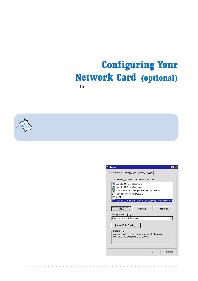
2. From the Configuration tab, select your
TCP/IP protocol.
(The example shown here is TCP/IP->
3Com EtherLink III ISA [3C509b-TPO]
in PnP mode. Select the Network Card
model that is listed in your system.)
Click Properties.
(If you do not see your networking
protocol, re-install your Network card.)
(optional)
TURBO 900.
○○○○○○○○○○○○○○○○○○○○○○○○○○○○○○○○○○○○○○○○○
42
Page 43

6. Configuring Your Ethernet Card (optional)
3. Select the IP Address tab.
Click the option 'Specify an IP address'.
Enter the IP Address as 192.168.1.2 and the Subnet Mask as 255.255.255.0.
Click OK.
This completes your Network Card configuration. You can now run the DSLTEST utility.
Please refer to Appendix C - Troubleshooting Guide, I am not able to connect to the
Internet. for details.
○○○○○○○○○○○○○○○○○○○○○○○○○○○○○○○○○○○○○○○○○
43
Page 44

Chapter 7
Connecting to the Internet
This chapter guides you on how to establish your connection for
7.1 Establishing the Connection for Broadband
Service
1. To connect to the Internet, double-click on the WinPoET dial-up icon on your Windows
desktop.
(This icon was generated during the installation of WinPoET software. If you do not
see the icon from your Windows desktop, re-install your WinPoET Dialer as described
in Chapter 5 - Installing WinPoET Dialer & DSLTEST.)
2. Enter your user-id@isp and password as given by your Internet Service Provider.
Select Save password if you want the
password to be remembered by your
system.
(You do not have to re-enter the password
the next time you connect.)
Click Connect.
Broadband Service.
If you are not able to establish
your Internet connection, please
refer to Appendix C -
Troubleshooting Guide on ‘
not able to connect to the
Internet.
○○○○○○○○○○○○○○○○○○○○○○○○○○○○○○○○○○○○○○○○○
44
’
I am
Page 45
7. Connecting to the Internet
Upon successful connection, you should be able to see an icon ( ) displayed at the corner
of your Windows taskbar.
7.2 Ready to Go!
You are now connected to the Internet.
Launch your Internet Browser (Internet Explorer / Netscape Navigator / Netscape
Communicator and so on).
You may start surfing!
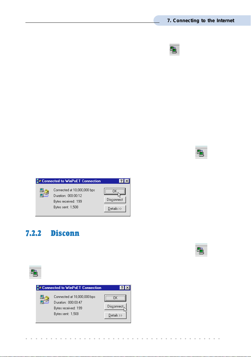
7.2.1 Checking the Session Connection time
If your connection to the Internet is established, you should see an icon ( ) displayed
at the corner of your Windows taskbar. Double-click on the icon. Check your connection
time by looking at the Duration.
(The connection speed shown is only an
example. Your actual connection speed
will depend on the subscription plan that
you have signed-up with your Internet
Service Provider.)
7.2.2 Disconnecting from the Internet
If your connection to the Internet is established, you should see an icon ( ) displayed
at the corner of your Windows taskbar. Close your web browser. Double-click on the icon
(
). Click Disconnect.
(The connection speed shown is only an
example. Your actual connection speed
will depend on the subscription plan that
you have signed-up with your Internet
Service Provider.)
○○○○○○○○○○○○○○○○○○○○○○○○○○○○○○○○○○○○○○○○○
45
Page 46
Chapter 8
Uninstalling WinPoET Dialer
& DSLTEST
For Windows® 98 Second Edition users, depending on your system
configurations, Windows may prompt for your Windows CD-ROM to complete
the uninstallation of WinPoET software. Please have the CD-ROM by your
side.
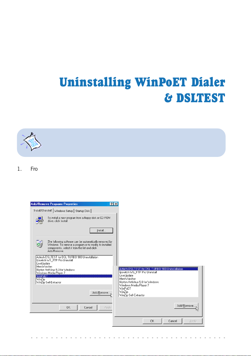
1. From your Windows taskbar, click Start > Settings > Control Panel. Double-click on
the Add/Remove Programs icon.
2. To uninstall WinPoET Dialer, select WinPoET and click Add/Remove.
Follow the on-screen instructions to complete the uninstallation.
3. To uninstall DSLTEST, select Aztech
DSLTEST for DSL TURBO 900
Uninstallation and click Add/
Remove.
Follow your on-screen instructions to
complete the uninstallation.
○○○○○○○○○○○○○○○○○○○○○○○○○○○○○○○○○○○○○○○○○
46
Page 47

Appendix A
Technical Specifications
This chapter contains the technical specifications for your NC2100(Lite)
NetCard and DSL TURBO 900. The information may be more useful
A.1 For NC2100(Lite) NetCard
A.1.1 Main Features
Highly integrated and cost-effective single-chip fast ethernet controller
Supports 32-bit PCI-Bus Master for high performance
Compliant to PCI Revision 2.2 specification
Supports IEEE 802.3 Auto-Negotiation algorithm of full-duplex and half-duplex operation
for 10Mbps and 100Mbps, that is, the network speed is auto-detected
Compliant to PC98/99
Half/Full duplex capability
Supports LED pins for various network activity indications
for technically inclined users.
A.1.2 Technical Data
Network Type:
Ethernet 10BASE-T
IEEE 802.3 industry standard for a 10Mbps baseband CSMA/CD local area network.
Fast Ethernet 100BASE-TX
IEEE 802.3u industry standard for a 100Mbps baseband CSMA/CD local area
network.
A.1.3 Network Operating System
Window® 95, 98, Me
Window® 2000
○○○○○○○○○○○○○○○○○○○○○○○○○○○○○○○○○○○○○○○○○
47
Page 48

A. Technical Specifications
A.1.4 Electrical
Power: 2Watts (max) @ 400 mA
A.1.5 Connector and Sockets
1 RJ-45 Shielded Phone Jack
A.1.6 LED
3 Green 3.0mm LEDs:
LINK
ACTIVE
100Mbps
1 The actual downstream and upstream rates will depend on the service package offered by your ADSL
Service Provider.
○○○○○○○○○○○○○○○○○○○○○○○○○○○○○○○○○○○○○○○○○
48
Page 49
A. Technical Specifications
A.2 For DSL TURBO 900
A.2.1 Main Features
Controller-based External ADSL Modem
UTOPIA Specifications Level I and Level II compliant
ANSI T1.413 issue 2, ITU-T G.992.1 (G.dmt) and G.992.2 (G.lite) compliant
Using Discrete Multi-Tone (DMT) line encoding scheme
Full Rate transmission at up to 8 Mbps downstream and 640 Kbps upstream
G.lite transmission at up to 1.5 Mbps downstream and 512 Kbps upstream
Rate Adaptive modem at 32 Kbps steps
Up to 18,000 ft loop reach
Flash ROM upgradable for future feature enhancement
RFC1483 Bridged (Ethernet Over ATM) protocol stack support
Remote management through Telnet console access
TFTP Software update
• Spectral compatibility with POTs
A.2.1.1 ADSL Chipset
Using ST Microelectronics Ascot solution:
Virata VC8410 (Helium) ATM Communications Controller
STLC70135 - ADSL DMT Modem and ATM Framer
STLC70134 - ADSL Analog Front End
4MB Dual-ported SDRAM
1MB Flash ROM
1
1
A.2.1.2 Virata VC8410 (HELIUM) ATM Communications Controller
Built-in 48MHz ARM-based Protocol and Network Processor
UTOPIA Level I v1.0 and Level II interface
10BaseT Ethernet interface with integrated PHY
Dual-ported SDRAM Interface
ATM Cell Header Filter
STLC70135 Configuration Register Interface
+3.3-volt, 208-pin PQFP
○○○○○○○○○○○○○○○○○○○○○○○○○○○○○○○○○○○○○○○○○
49
Page 50

A. Technical Specifications
A.2.1.3 STLC70135 ADSL DMT MODEM & ATM FRAMER
ANSI T1.413 Issue 2 standard DMT modem with embedded ATM Framer
ITU-T G.992.1 (G.dmt) and G.992.2 (G.lite) compliant
Standard Utopia Level I and Level II ATM Interfaces
DMT Modulation up to maximum of 256 tones (14 bits)
ADSL/ATM cell-specific Framing and Deframing
Rotor and Frequency Domain Gain Correction and Equalization
Performs DMT Modulation, Demodulation, Reed-Solomon Encoding, Bit Interleaving,
and 4D Trellis Coding
3.3-volt, 144-pin PQFP
A.2.1.4 STLC70134 ADSL Analog Front-end
Integrated Analog Front End (AFE) for ADSL
High sampling rate at 8.832 MHz for both ADC and DACs
Two (2) 12-bit DACs, One 13-bit ADC
Differential Analog Input/Output
Accurate continuous-time low pass filters for channel filtering
3.3-volt, 64-pin LQFP
A.2.2 ADSL Software Support
ATM Transmission Convergence (TC) layer
ATM Layer with Traffic shaping
AAL ATM Attributes - AAL5
RFC-1483 Bridged (Ethernet Over ATM)
RFC-2516 PPP over Ethernet (Supported via Optional Software)
PPTP Tunneling Protocol (when available)
UNI 3.0, 3.1 and UNI 4.0 ATM Signaling (support for SVCS)
A.2.3 Platform Support
• Windows
• Windows
○○○○○○○○○○○○○○○○○○○○○○○○○○○○○○○○○○○○○○○○○
50
®
95, 98, Me
®
2000
Page 51
A.2.4 External Connectors
1 x RJ11 Telephone socket for ADSL line
1 x RJ11 Telephone socket for Telephone Handset
1 x RJ45 for 10Base-T Ethernet
1 x MiniDIN Power Connector
1 x On/Off Power Switch
9 pin Serial Port for local management
A.2.5 LED Indicators
1 x Power LED
1 x Ethernet Link Status LED
1 x Ethernet Activity LED
1 x ADSL Receive LED
1 x ADSL Transmit LED
1 x ADSL Link Status LED
A.2.6 Environmental
A. Technical Specifications
A.2.6.1 Temperature
Operating : 10o to 45 o Celsius (50 o to 113 o Fahrenheit)
Non-Operating : -25
o
to 70 o Celsius (-13 o to 158 o Fahrenheit)
A.2.6.2 Humidity
Operating : 30% to 80% Relative Humidity (Non-Condensing)
Non-Operating : 10% to 95% Relative Humidity (Non-Condensing)
A.2.7 System Requirements
Pentium MMX 233MHz or equivalent
The specifications herein are subject to change without prior notifications.
○○○○○○○○○○○○○○○○○○○○○○○○○○○○○○○○○○○○○○○○○
51
Page 52

Appendix B
Frequently Asked
This section provides answers to the commonly asked questions
What is ADSL ?
ADSL, Asymmetric Digital Subscriber Line, is a broadband communication
technology designed for use on regular phone lines. It has the ability to move
data over the phone lines at speeds up to 140 times faster than the analog modem
available today.
Why is it called Asymmetric ?
It is called asymmetric because more bandwidth is reserved for receiving data
than for sending data. This is useful because many users of the Internet receive
much more data than they send.
Questions
on your ADSL modem.
What are the benefits of ADSL over analog modems ?
Besides the high-speed advantage, ADSL connection is always on. There is no
longer a need to log on and off, no more busy signals and no more waiting for the
connection to established - it is always there. On top of these, you can use the
phone even when the data connection is on. You do not need to switch between
surfing the Net and talking over the phone.
Will my modem constantly connect near the maximum speed ?
At ADSL speeds, the limitations depend on the performance or load of the Internet
Service Provider that you are trying to reach, as well as the line condition specific
to your location.
○○○○○○○○○○○○○○○○○○○○○○○○○○○○○○○○○○○○○○○○○
52
Page 53

B. Frequently Asked Questions
Can I connect to Broadband Service everywhere I go?
No, you cannot. You can connect to this service, only via ADSL phone line enabled
for Broadband Service provided by your Internet Service Provider (ISP).
Can I use my Broadband Service user ID to log in to 56K dial-up access on a
normal telephone line using a 56K dial-up modem?
Yes, you can.
Can I run both dial-up modem and ADSL modem ?
Yes, but it is not recommended. You may experience slowness during surfing as
well as incurring additional cost of maintaining two active connections.
Do I need to use Micro-Filter when using ADSL ?
DSL TURBO 900 has a built-in Micro-Filter at the Phone jack. Thus no Micro-
Filter is required between your Telephone set and the modem.
However, if you are sharing the ADSL line with other telephone line extensions,
you will need to have a Micro-Filter connected between the Telephone set and the
telephone wall socket as shown in section 4.1 - Setup Overview.
(The Micro-Filters can be purchased separately from your dealer.)
Can I determine which version of Dial-Up Network (DUN) is installed ?
There is no easy way to determine the version of the DUN. The safest approach is
to install the latest DUN version downloaded from the Microsoft website.
How do I install Microsoft Dial-Up Networking version 1.3 and above ?
i. Download Microsoft Dial-Up Networking program from the Microsofts website:
http://www.microsoft.com.
ii. In the Microsoft Search path, enter Msdun13.exe. From the results listed,
locate and select the listing similar to MSDUN13.EXE: Dial-Up Networking
1.3 Upgrade.
iii. Click Msdun13.exe to download the file to your harddisk.
[file size is about 2.4MBytes]
○○○○○○○○○○○○○○○○○○○○○○○○○○○○○○○○○○○○○○○○○
53
Page 54
B. Frequently Asked Questions
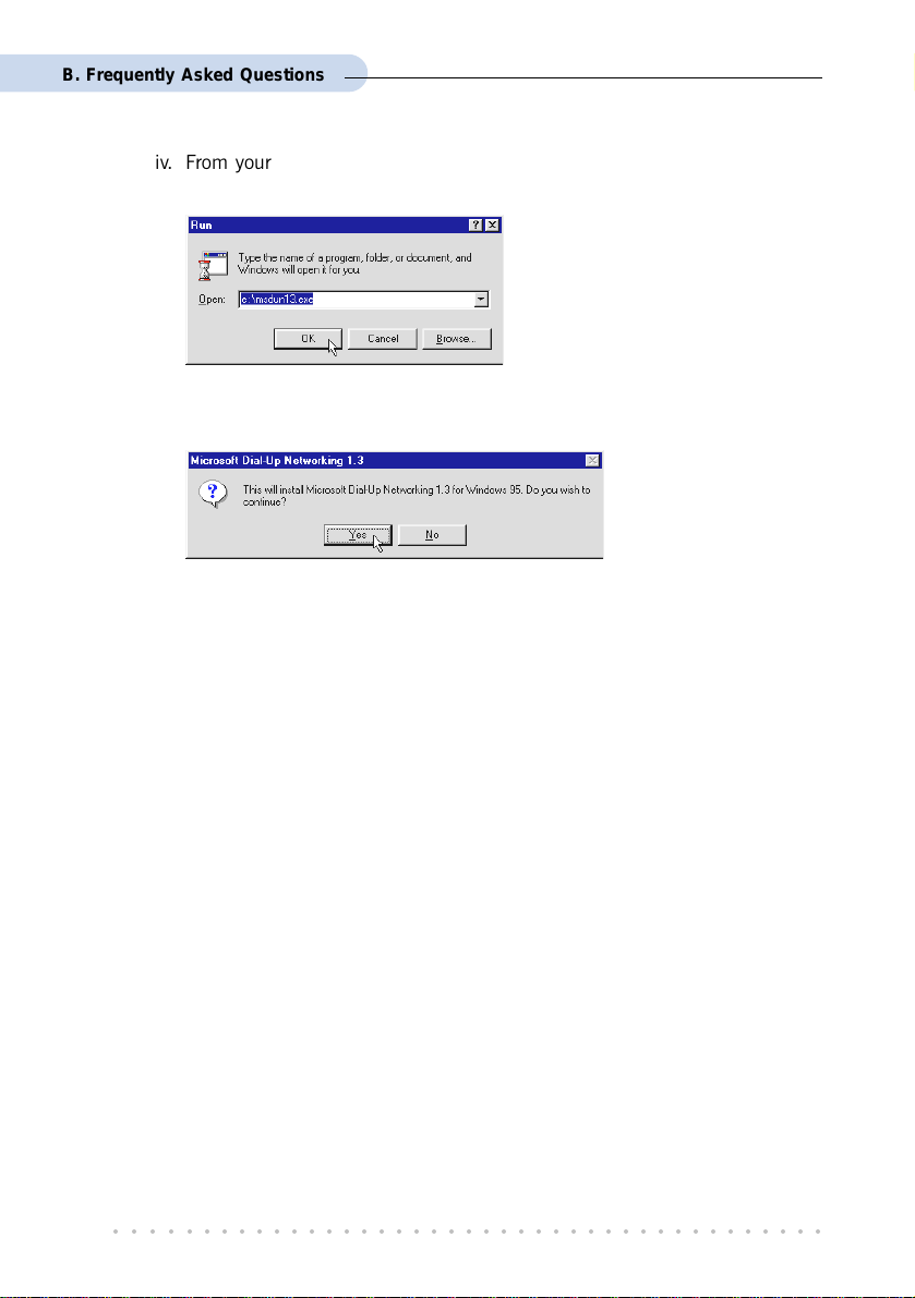
iv. From your Windows taskbar, click Start > Run.... Browse to the directory
where you have downloaded Msdun13.exe. Select the file and click OK.
Click OK again.
v. Click Yes to proceed.
vi. At the Microsoft TCP/IP Networking prompt, click OK.
vii. When prompted to restart, click OK.
○○○○○○○○○○○○○○○○○○○○○○○○○○○○○○○○○○○○○○○○○
54
Page 55

Appendix C
Troubleshooting Guide
This section provides a step-by-step solutions to problems that
you may encounter when setting up or using your ADSL modem.
I am not getting any connection. The modem Power LED lights up and the ADSL
Link LED keeps blinking. (The ADSL Link LED does not remain light up.)
Power off your modem and check the following:
i) Ensure that the Power adapter is tightly fitted into the DC IN.
ii) Check that the Telephone cable (RJ-11) is connected to LINE jack on your
modem and not to the TEL jack.
iii) Power on your modem.
If the problem still persist, please check with your Internet Service Provider.
I am getting poor ADSL speed performance from my modem.
i) Ensure that the ADSL line is at least 10cm away from the Power adapter.
(see Figure C-1. Distance between your ADSL Line and Power adapter)
ii) Place your modem away from devices or appliances such as monitors, exposed
computer systems (with chassis covers removed) or another modem which
exhibit magnetic fields that may cause interferences to your modem line.
iii) Ensure that Micro-Filters are used for phone sockets that are sharing the same
ADSL line.
If your modem speed or performance is still unsatisfactory, please contact your
Internet Service Provider.
○○○○○○○○○○○○○○○○○○○○○○○○○○○○○○○○○○○○○○○○○
55
Page 56

C. Troubleshooting Guide
Mains Supply
Power adapter
Rear view of
DSL TURBO 900
be greater than 10cm
Telephone wall
socket
Telephone cable (RJ-11) -
ADSL Line
Figure C-1. Distance between your ADSL Line and Power adapter
My WinPoET dialer seems to hang at the status Connecting to communications
device..
Verify the following:
i) Your modem is connected to the ADSL line.
ii) The Mains Supply at the power adapter is powered on.
iii) The Switch on your modem is at the I position.
iv) The Ethernet cable is connected from your modem to your Ethernet card.
(see section 4.2 - Connecting DSL TURBO 900)
For any re-connections made, allow some time for system to re-establish the
Internet link. If the connection still fail, please proceed with the next question, I
am not able to connect to the Internet. for further tests.
○○○○○○○○○○○○○○○○○○○○○○○○○○○○○○○○○○○○○○○○○
56
Page 57

C. Troubleshooting Guide
I am not able to connect to the Internet.
Carry out the following test to verify your connections.
1. Please ensure that you have proceeded with Chapter 6 -
Configuring Y our Network Card before running DSL TEST for
DSL TURBO 900.
2. If one of the test failed, subsequent tests will be skipped.
Please proceed to fix the problem first before running the
test program again.
1. From your Windows desktop, double-click on DSLTEST icon.
2. Click Test. (Table C -2 gives the description of the tests.)
The tests listed will
commence. You should
get a PASS for all the
tests.
Should your test(s) fails,
please refer to Table C-2
for the solution.
Test Description Result=FAIL
Interface test
Modem test
Network test
To test if your driver is installed
properly.
To check if your sy stem is
communicating with the modem .
To check if the Internet
connection is ok.
Re-install your modem driver.
Check with your Internet ADSL
Service Provider.
Table C-2. Test Descriptions.
○○○○○○○○○○○○○○○○○○○○○○○○○○○○○○○○○○○○○○○○○
57
Page 58
C. Troubleshooting Guide
During the installation of WinPOET, an error message, No Microsoft TCP/IP
stack installed. Please install the Microsoft TCP/IP stack in Control Panel,
Network. is prompted. (For Windows
You need to install Microsoft TCP/IP before installing WinPOET. Please refer to
section 3.3.1 - Verifying NC2100(Lite) NetCard, step 3 on the installation
procedures.
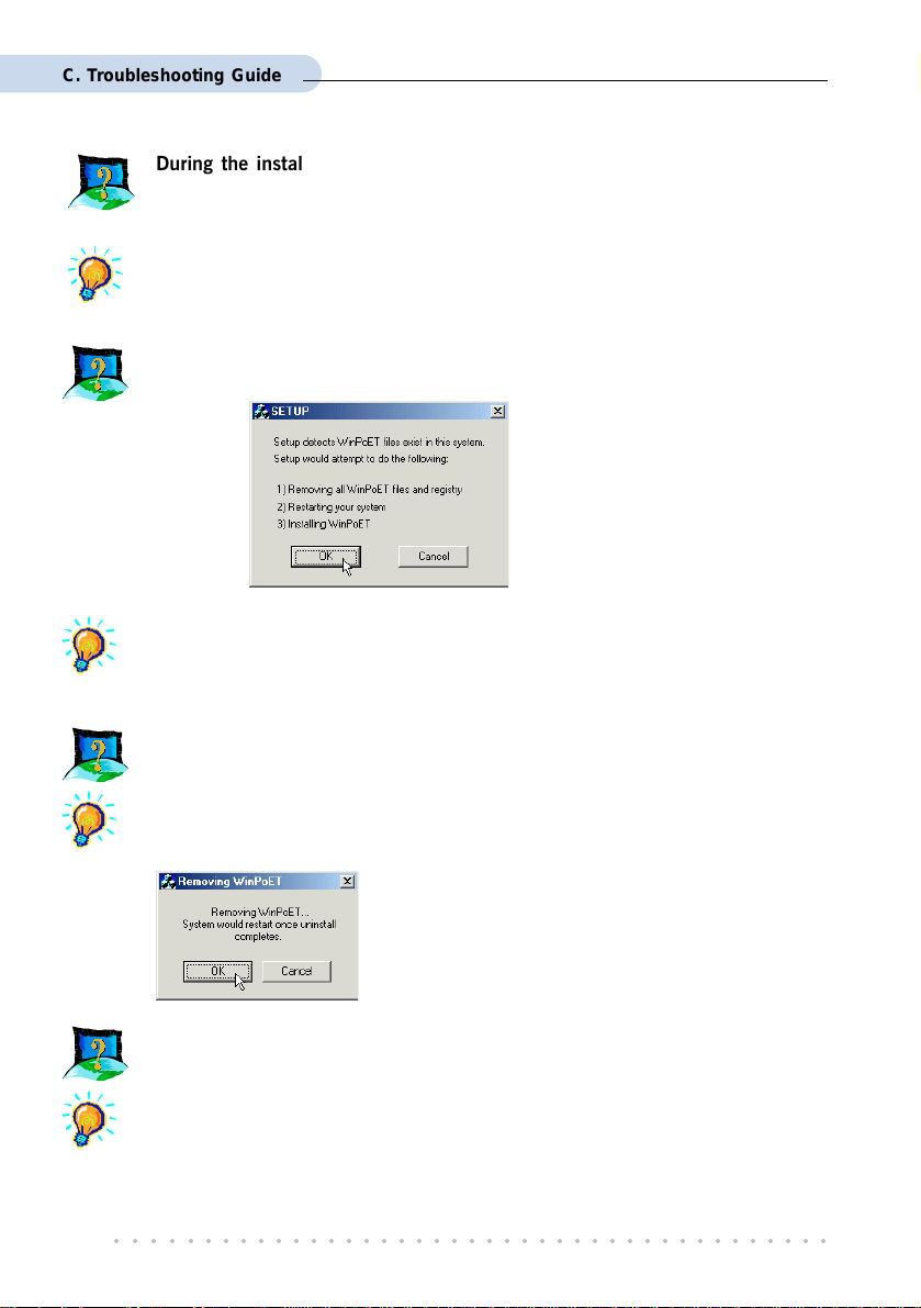
The following window is prompted when I run WinPoET setup.
The setup detected that you already have WinPoET installed in your system. It
would remove all WinPoETs files and registry entries before reinstalling WinPoET
again. Click OK to proceed.
®
95 users only)
I cannot uninstall WinPoET from Add/Remove Programs and reinstall WinPoET
again.
Locate a Clean folder on your DSL 900E CD-ROM. Double-click on Clean.exe
from the folder. You should see the following window. Click OK to proceed.
Follow on-screen instructions. Restart your system
once the cleaning up of the WinPoETs files and
registry entries are completed. You can now reinstall
WinPoET again.
A blue screen suddenly popped up, indicating PgDetect.exe is the cause of the
problem.
Refer to the above solution I cannot uninstall WinPoET from Add/Remove
Programs and reinstall WinPoET again to reinstall your WinPOET.
○○○○○○○○○○○○○○○○○○○○○○○○○○○○○○○○○○○○○○○○○
58
Page 59

Appendix D
Technical Support
D.1 Aztech Sales Enquiries
Hotline : (65) 741 7211 (Marketing and Sales Department)
Email : sales@aztech.com
Fax : (65) 749 1198
Working Hours : Monday to Friday - 0900 to 1700
Saturday/Sunday/Public Holidays - Closed
D.2 Aztech Technical Support
Hotline : (65) 749 2062
Email : support@aztech.com
Fax : (65) 749 1198
Working Hours : Monday to Friday - 0900 to 1700
Saturday/Sunday/Public Holidays - Closed
D.3 Technical Support Considerations
Majority of enquiries can be resolved efficiently. However, there may be cases when it is
beyond our technical support to assist you. We may not be able to assist you in:
Hardware conflicts
We will try to discover them and make suggestions but we are unable to repair them
over the telephone.
Software conflicts
Removal of other software and reinstalling our software may be the only solution.
○○○○○○○○○○○○○○○○○○○○○○○○○○○○○○○○○○○○○○○○○
59
Page 60

D. Technical Support
O/S problem
If you encounter problems like fatal exception or illegal operation, kindly refer to your
PC vendor.
Modifications made to your software
Our technical support officers are trained to support the software we provide as part
of our service and they are knowledgable about a wide range of other programs.
However, we are unable to support software that has been modified.
○○○○○○○○○○○○○○○○○○○○○○○○○○○○○○○○○○○○○○○○○
60
Page 61

Notes
Page 62

Notes
Page 63

Page 64

Copyright Aztech Systems Ltd, August 2001
©
P/N: 040-5B2451-121
 Loading...