

Page 1
DSL Router Commander
Software Manual
Version 1.2
Windows® 95, Windows® 98, Windows® 98 Second Edition, Windows® Me,
Windows® XP, Windows NT®4.0 and Windows® 2000 supported
Page 2

Product warranty does not apply to damage caused by lightning, power surges or
wrong voltage usage.
© Copyright November 2001. All Rights Reserved.
(P/N: 040-510447-121) (Ref: 9009000)
Page 3

Contents
Introducing DSL Router Commander ..........................................4
1
1.1 Logging In...................................................................................... 4
1.2 Getting Ready Information Required.................................................. 5
Network Setup Overview ..............................................................7
2
2.1 Configuring the PCs ........................................................................ 8
Configuring your Router with DSL Router Commander ..............9
3
3.1 Line Configuration .......................................................................... 12
3.1.1 Configuring for RFC 2684 (RFC 1483) Bridged ................. 13
3.1.1a NAT Inbound (optional) ................................... 19
3.1.2 Configuring for RFC 2684 (RFC 1483) Routed.................. 21
3.1.3 Configuring for RFC 2225 (RFC 1577) ............................. 23
3.1.4 Configuring for RFC 2516 ............................................... 24
3.1.5 Configuring for RFC 2364 ............................................... 25
3.1.6 Configuring for Transparent Bridge ................................... 28
3.2 Route Table .................................................................................... 31
3.3 DHCP ........................................................................................... 33
3.3.1 Configuring Your Ethernet card for DHCP .......................... 35
3.4 SNMP ........................................................................................... 38
3.5 DSL Monitoring .............................................................................. 40
Glossary ........................................................................................42
Index .............................................................................................47
3
Page 4

Chapter1
Introducing DSL
Router Commander
DSL Router Commander is a user-friendly interface that allows you to initialize, view and
modify your Router configurations to match the characteristics of your network environment.
1.1 Logging In
1. Place the Installation CD into your CD-ROM Drive. You will be prompted with a
Modem Installation Wizard. Click Cancel.
Run DSL Router Commander by running DslCom.exe file from \Advanced\Tools\DSL
Router Commander folder on the Installation CD.
2. You will be prompted for your log in password. Enter the password as stm (factory's
default) and click OK.
(The factory default for Router IP Address and Password is 192.168.1.1 and stm respectively.
Replace them with your new Router IP Address and Password if your System Administrator
has changed them.)
4
Page 5

Software Manual
You may also change your login password by selecting the SNMP tab from
the DSL Router Commander.
1.2 Getting Ready Information Required
To configure your Router, you need to have the following information ready from your ADSL
Service Provider and System Administrator.
The following table shows the information required.
a) Check with your ADSL Service Provider:
i) The line protocol to use
ii) For RFC 2684 (RFC 1483) / RFC 2225 (RFC 1577):
The addresses for
WAN IP
WAN Subnet Mask
VPI and VCI values
Default WAN Gateway
DNS Relay (Enable/Disable)
DNS Server (Primary)
DNS Server (Secondary)
For RFC 2516 / RFC 2364:
The PPP Authorization's
VPI and VCI values
User Name
Password
Channel
Authentication
DNS Relay (Enable/Disable)
DNS Server (Primary)
DNS Server (Secondary)
iii) The Framing Mode
[not applicable for RFC 2225 (RFC 1577)]
5
Page 6

Software Manual
b) Check with your System Administrator:
i) The addresses for
LAN IP address
LAN Subnet Mask
Remote Gateway
ii) To enable or disable NAT
6
Page 7
Chapter2
Network
Setup Overview
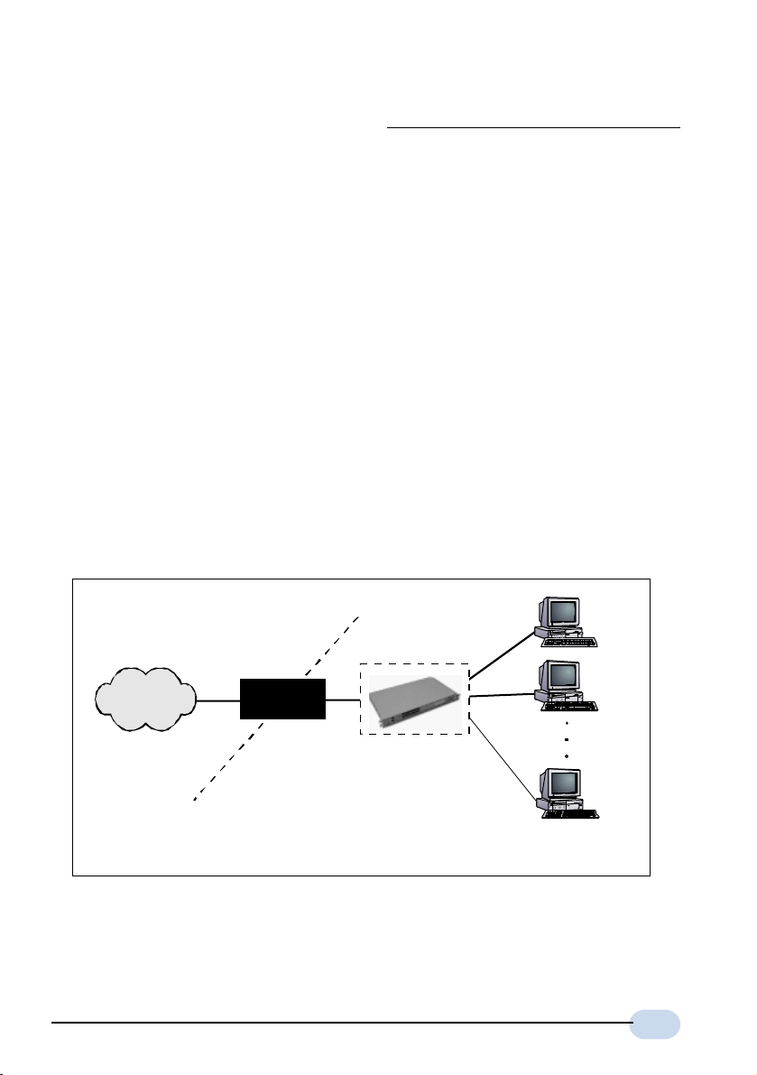
This section gives an overview of a typical network. The addresses indicated are used as
examples throughout the whole manual. You are to replace them with values given by your
System Administrator / ADSL Service Provider.
WAN Gateway = 202.166.29.2
WAN IP
202.166.29.154
ADSL
PVC=0/35
WAN
(The Hub/Switch shown on the diagram is optional if your Router already has more than
1 Ethernet Ports)
Your Router
LAN IP
192.168.1.1
202.166.30.1 (without NAT)
LAN
(with NAT)
Hub/Switch
PC A
PC B
PC X
PCs with
Ethernet cards
7
Page 8

Software Manual
1. For configuration without NAT:
The range of the IP address used in this example is from 202.166.30.1 to
202.166.30.6 as restricted by subnet mask defined.
Network ID : 202.166.30.0 Broadcast ID :202.166.30.7
The ADSL Service Provider will have to create a static route:
Network ID : 202.166.30.0 Subnet Mask : ff:ff:ff:f8
Next Hop Gateway : 202.166.29.154
For PPPoA and PPPoE:
2.
The WAN IP and WAN Gateway will be dynamically assigned by the PPP
server. There is no need to specify the WAN IP nor to configure a default
route to the WAN Gateway.
2.1 Configuring the PCs
For PC A:
(with NAT) (without NAT)
IP = 192.168.1.11 = 202.166.30.2
Subnet mask = 255.255.255.0 = 255.255.255.248
Gateway = 192.168.1.1 = 202.166.30.1
For PC B:
(with NAT) (without NAT)
IP = 192.168.1.12 = 202.166.30.3
Subnet mask = 255.255.255.0 = 255.255.255.248
Gateway = 192.168.1.1 = 202.166.30.1
For PC X:
(with NAT) (without NAT)
IP = 192.168.1.23 = 202.166.30.6
Subnet mask = 255.255.255.0 = 255.255.255.248
Gateway = 192.168.1.1 = 202.166.30.1
8
Page 9

Chapter3
Configuring your Router with
DSL Router Commander
1. For any settings that you are unsure, please check with your ADSL Service Provider or System Administrator.
2. Based on your selected line configuration, fields that are not applicable
will be grayed out.
3. The values in the screen shots are based on the examples in Chapter 2
- Network Setup Overview. You are required to replace these values
with those given by your ADSL Service Provider or System Administrator!
9
Page 10
Software Manual
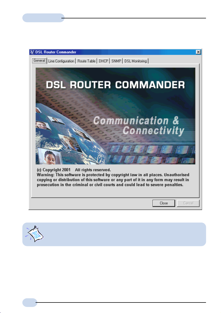
Once you are logged in, you will see the following Main Menu.
10
Always click Close on the menu to save any changes you have made to your
configurations. If you exit DSL Router Commander without clicking on
Close, changes you have made will be lost!
Page 11

Software Manual
The following describes the menu items:
Line Configuration (see section 3.1 for details)
To select the desired protocol and configure the IP addresses/Subnet Mask that is required
for your network. You may set, modify or view the settings for your configuration.
Route Table (see section 3.2 for details)
To set, view or delete static route(s).
DHCP (see section 3.3 for details)
To add, modify or view the DHCP server for your local network.
(DHCP allows centralized configuration of all workstations TCP/IP protocol and IP address
allocation from the server.)
SNMP (see section 3.4 for details)
To manage the list of SNMP community names.
DSL Monitoring (see section 3.5 for details)
To monitor the activities of your Router from the computer connected to it. Click Close to
exit DSL Router Commander.
11
Page 12

Software Manual
3.1 Line Configuration
The different types of configurations available are:
RFC 2684 (RFC 1483) Bridged or Ethernet Framing
Encapsulation of bridged network data, such as Ethernet frames, in ATM
Adaptation Layer 5 (AAL5) Protocol Data Units (PDU).
RFC 2684 (RFC 1483) Routed or IP Framing
Encapsulation and Transmission of routed network data, such as IP datagrams,
over ATM Adaptation Layer 5 (AAL5) Protocol Data Units (PDU).
RFC 2225 (RFC 1577) IPoA
Transmission of IP datagrams and ATM Address Resolution Protocol (ATMARP)
requests and replies over ATM Adaptation Layer 5 (AAL5).
RFC 2516 PPPoE
Creation and maintenance of a Point-to-Point-Protocol (PPP) session over an
Ethernet link.
RFC 2364 PPPoA
Creation and maintenance of a Point-to-Point-Protocol (PPP) session over an
ATM link.
Transparent Bridge
Joining two or more bridged network segments (such as Ethernet) running on
different physical media.
12
Page 13
Software Manual
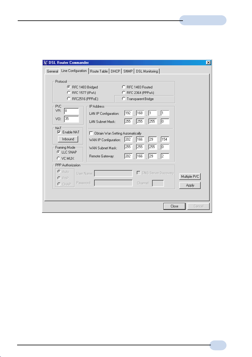
3.1.1 Configuring for RFC 2684 (RFC 1483) Bridged
i) Select Line Configuration tab. In the Protocol section, click RFC 1483 Bridged.
ii) In the PVC section, enter the VPI and VCI values as assigned by your ADSL Service
Provider.
iii) In the IP Address section, enter all the required IP addresses as assigned by your ADSL
Service Provider or System Administrator.
(Depending on your ADSL Service Provider, you may select the option Obtain Wan
Setting Automatically. The WAN IP Configuration, WAN Subnet Mask and Remote
Gateway fields will be grayed out. The addresses will be allocated by your ADSL
Service Provider's Server automatically.)
iv) Select the NAT option as determined by your System Administrator. If required, click
Inbound and fill in the data. (See section 3.1.1a - NAT Inbound)
v) Select the Framing Mode option as determined by your ADSL Service Provider.
13
Page 14
Software Manual
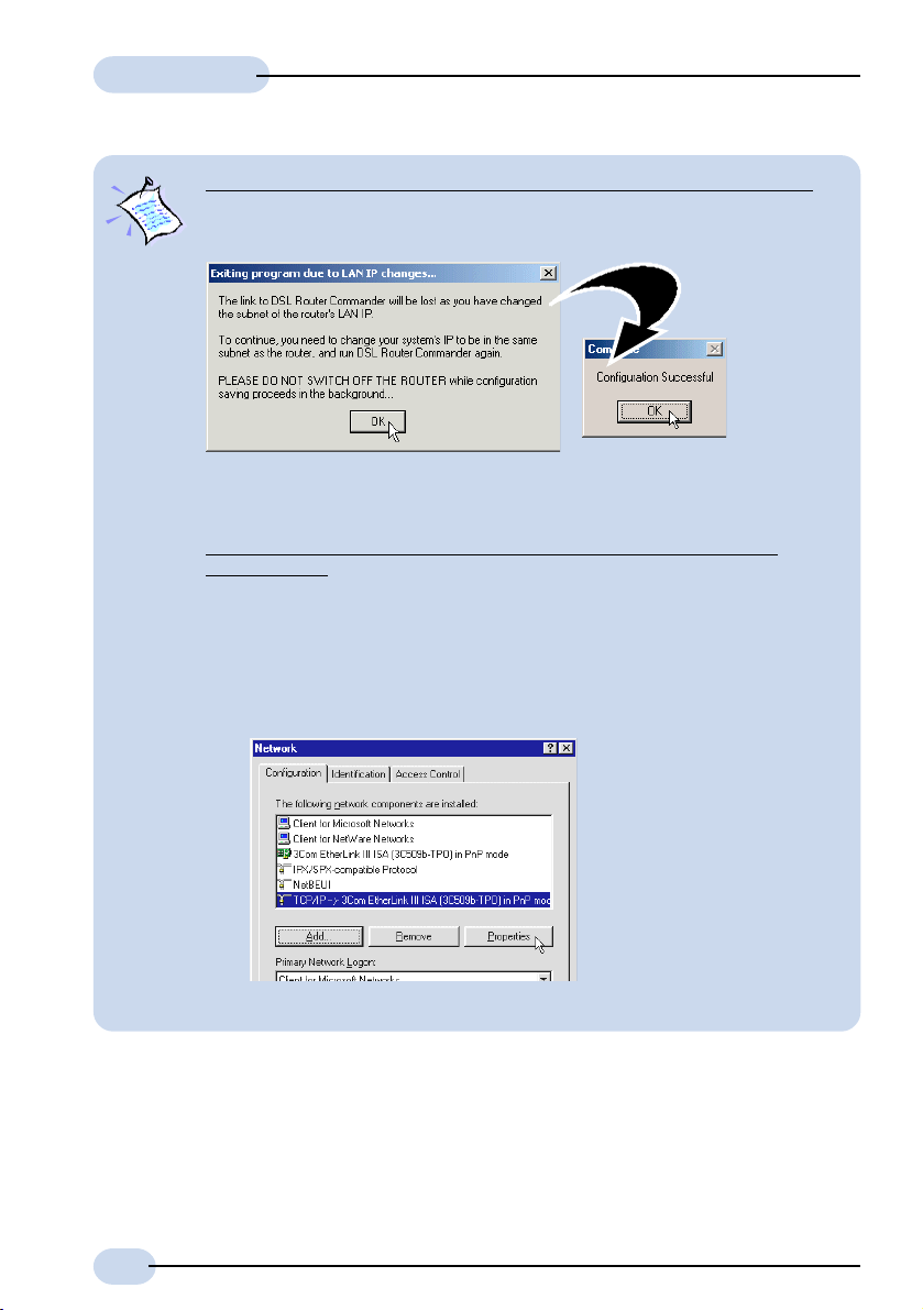
Changing LAN IP address / Subnet Masks (applicable to all protocols):
If you overwrite the default LAN IP address / Subnet Mask with new addresses
and click Apply, the following dialog box will be prompted.
Understand the instructions. Click OK to both prompts. Proceed to change your
Ethernet Card's IP / Subnet Mask by carrying out the following steps:
For Windows® 95 / Windows® 98 / Windows® 98 Second Edition /
Windows® Me
a) From your Windows desktop, right-click on the Network Neighborhood
b) From the Configuration tab, select the 'TCP/IP->xxx' where xxx refers to
icon and select Properties.
the model of your Ethernet card that is connected to your Router.
(3Com EtherLink III Ethernet Card is used as an example here.)
Click Properties.
14
(If you do not see TCP/IP with
the model of your Ethernet Card,
refer to the documentation that
comes with your card and re-
install the driver.)
continue on next page...
Page 15
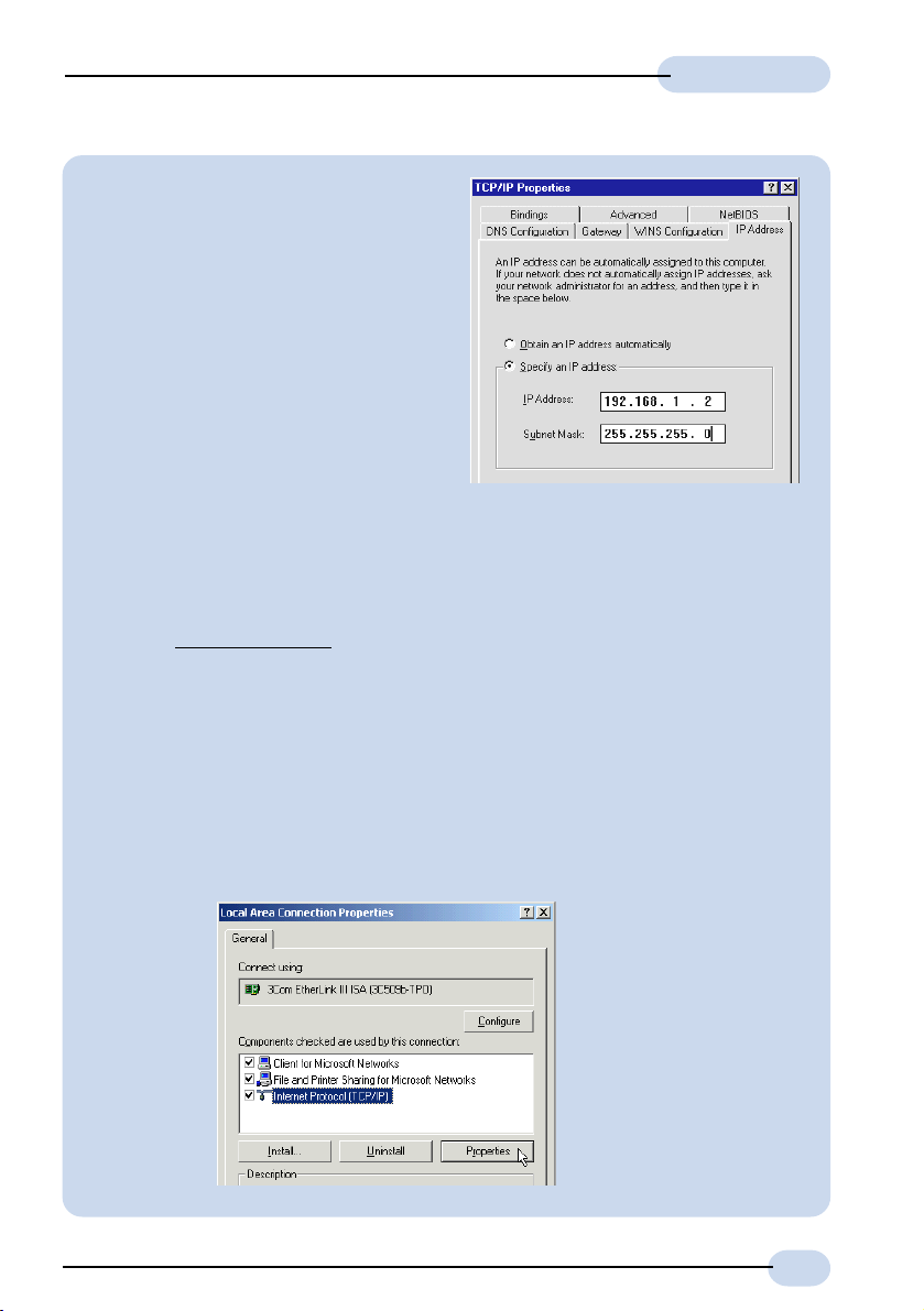
c) From the IP Address tab, overwrite
the existing IP Address / Subnet
Mask to the same subnet as the
LAN IP / Subnet Mask you have
entered at the DSL Router
Commander.
Click OK and restart you system if
prompted.
You can now run the DSL Router
Commander with the new IP
address.
If you have set the subnet mask of the LAN IP to 255:255:255:255, you will
not be able to run DSL Router Commander. This is because only one IP is
allowed on the LAN network and it is already allocated to the Router.
For Windows® XP
i) From your Windows desktop, click Start > All Programs > Accessories >
Communications > Network Connections.
Right-click on the Local Area Connection icon that reflects the model of
your Ethernet Card that is connected to your Router and click Properties.
(This is important especially if you have mor e than one Local Ar ea
Connection icons displayed. If you do not see the model of your
Ethernet Card, refer to the documentation that comes with your
Ethernet card and re-install the driver.)
ii) Select Internet Protocol (TCP/IP) and click Properties.
Software Manual
(3Com EtherLink III Ethernet
Card is used as an example
here.)
15
Page 16

Software Manual
iii) Select the option Use the following IP address. Overwrite the existing IP
If you have set the subnet mask of the LAN IP to 255:255:255:255, you will
not be able to run DSL Router Commander. This is because only one IP is
allowed on the LAN network and it is already allocated to the Router.
Address, Subnet Mask and Default gateway to the same subnet as the
LAN IP / Subnet Mask you have entered at the DSL Router Commander.
Click OK again to close.
You can now run the DSL Router Commander with the new IP address.
16
For Windows® 2000
i) From your Windows desktop, right-click on the icon My Network Places.
Select Properties.
At the Network and Dial-up Connections window, right-click on the Local
Area Connection icon and select Properties.
continue on next page...
Page 17

Software Manual
ii) Ensure that the field Connect Using indicates the model of your
Ethernet card that is connected to your Router.
(This is important especially if you have more than one Local Area
Connection icons displayed
at the Network and Dial-up Connections
window. Ensure that you have selected the correct Local Area
Connection icon.)
Select Internet Protocol (TCP/IP) and click Properties.
(3Com EtherLink III Ethernet
Card is used as an example
If you cannot find the
here.
model of your Ethernet
Card that is connected to
your Router, refer to the
documentation that comes
with your Ethernet card and
re-install the driver.)
iii) Select the option Use the following IP address. Overwrite the existing IP
Address, Subnet Mask and Default gateway to the same subnet as the
LAN IP / Subnet Mask you have entered at the DSL Router Commander.
Click OK again to close.
You can now run the DSL Router Commander with the new IP address.
If you have set the subnet mask of the LAN IP to 255:255:255:255, you will
not be able to run DSL Router Commander. This is because only one IP is
allowed on the LAN network and it is already allocated to the Router.
17
Page 18

Software Manual
For Multiple PVCs:
vi) For multiple PVCs, click Multiple PVC.
- In the Protocol section, select RFC 1483 Bridged.
- In the IP Address section, enter the WAN IP Configuration and WAN Subnet
Mask addresses as assigned by your ADSL Service Provider / System
Administrator.
(The WAN IP Configuration must be a unique IP address for different set of
PVC values.)
Depending on your ADSL Service Provider, you may select the option Obtain
Wan Setting Automatically. The addresses will be allocated by your ADSL
Service Provider's Server automatically.
- In the PVC field, enter the new VPI and VCI values.
- Select the NAT option as determined by your System Administrator. If required,
click Inbound and fill in the data. (See section 3.1.1a - NAT Inbound)
- Select the Framing Mode option as determined by your ADSL Service Provider.
- Click Add. A protocol with the new PVC values entered will be listed.
(To remove a PVC value, click on the respective protocol and click Remove.)
- Click Apply for changes to take effect. Upon configuration successful, you will
see a dialog box, 'Configuration Successful' prompted. Click OK followed by
Close.
vii) Click Apply for changes to take effect. Upon configuration successful, you will see a
dialog box, 'Configuration Successful' prompted. Click OK.
viii) Click Close to save the configurations and exit.
18
Page 19

Software Manual
3.1.1a NAT Inbound (optional)
Inbound allows you to list or set up a series of rules to determine what will happen to the
incoming traffic. By default, all incoming packets other than packets arriving in response
to outgoing traffic, will be rejected.
The Interface (e.g. wan as shown in the dialog box below) listed in the table corresponds
to your configured WAN interface.
NAT should always be enabled only on the interface connecting to the
public network or WAN, not the interface connecting to the private network.
(Illustration is based on RFC 1483 Routed)
i) To add a rule:
Enter the Por t, Host IP Address and Protocol required and click Add.
Port Refers to a 16-bit number (range from 1 to 65535) used by
transport layer protocols (UDP or TCP). Ports are used to
address application or services which run on a Server.
Host IP Address Refers to the IP address of a local application server (e.g.
HTTP, FTP Server) that will service inbound traffic request
from Internet. The Router will forward those requests
according to the list.
Protocol Refers to the IP protocol, either TCP or UDP.
Port/Proto Refers to the Port and Protocol used for the interface.
New IP Addr Refers to the new IP address on the private network which
the packets destination IP address should be translated to.
19
Page 20

Software Manual
ii) To remove a single interface
To remove one of the interface, click on it and click Remove.
iii) To remove all interfaces
To remove all interfaces, click Remove All.
iv) Click Exit.
20
Page 21

Software Manual
3.1.2 Configuring for RFC 2684 (RFC 1483) Routed
i) Select Line Configuration tab. In the Protocol section, click RFC 1483 Routed.
ii) In the PVC section, enter the VPI and VCI values as assigned by your ADSL Service
Provider.
iii) In the IP Address section, enter all the required IP addresses as assigned to you by
your ADSL Service Provider / System Administrator.
iv) Select the NAT option as determined by your System Administrator. If required, click
Inbound and fill in the data. (See section 3.1.1a - NAT Inbound)
v) Select the Framing Mode option as determined by your ADSL Service Provider.
To change the LAN IP address / LAN Subnet Mask at the LAN IP Configuration
/ LAN Subnet Mask field, read the Note on page 14.
21
Page 22

Software Manual
For Multiple PVCs:
vi) For multiple PVCs, click Multiple PVC.
- In the Protocol field, select RFC 1483 Routed.
- In the IP Address section, enter the WAN IP Configuration and WAN Subnet
Mask addresses as assigned by your ADSL Service Provider / System
Administrator.
(The WAN IP Configuration must be a unique IP address for different set of
PVC values.)
- In the PVC field, enter the new VPI and VCI values.
- Select the NAT option as determined by your System Administrator. If required,
click Inbound and fill in the data. (See section 3.1.1a - NAT Inbound)
- Select the Framing Mode option as determined by your ADSL Service Provider.
- Click Add. A protocol with the new PVC values will be listed.
(To remove a PVC value, click on the respective protocol and click Remove.)
- Click Apply for changes to take effect. Upon configuration successful, you will
see a dialog box, 'Configuration Successful' prompted. Click OK followed by
Close.
vii) Click Apply for changes to take effect. Upon configuration successful, you will see a
dialog box, 'Configuration Successful' prompted. Click OK.
viii) Click Close to save the configurations and exit.
22
Page 23

3.1.3 Configuring for RFC 2225 (RFC 1577)
Software Manual
i) Select Line Configuration tab. In the Protocol field, click RFC 1577.
ii) In the PVC section, enter the VPI and VCI values as assigned by your ADSL Service
Provider.
iii) In the IP Address section, enter all the required IP addresses as assigned by your ADSL
Service Provider / System Administrator.
(Depending on your ADSL Service Provider, you may select the option Obtain Wan
Setting Automatically. The WAN IP Configuration, WAN Subnet Mask and Remote
Gateway fields will be grayed out. The addresses will be allocated by your ADSL
Service Provider's Server automatically.)
iv) Select the NAT option as determined by your System Administrator. If required, click
Inbound and fill in the data. (See section 3.1.1a - NAT Inbound)
v) Click Apply for changes to take effect. Upon configuration successful, you will see a
dialog box, 'Configuration Successful' prompted. Click OK.
vi) Click Close to save the configurations and exit.
To change the LAN IP address / LAN Subnet Mask at the LAN IP Configuration
/ LAN Subnet Mask field, read the Note on page 14.
23
Page 24

Software Manual
3.1.4 Configuring for RFC 2516
i) Select Line Configuration tab. In the Protocol field, click RFC 2516.
ii) In the PVC section, enter the VPI and VCI values assigned by your ADSL Service
Provider.
iii) In the IP Address section, enter all the required IP addresses assigned to you by your
ADSL Service Provider / System Administrator.
iv) Select the NAT option as determined by your System Administrator. If required, click
Inbound and fill in the data. (See section 3.1.1a - NAT Inbound)
v) Select the PPP Authorization as determined by your ADSL Ser vice Provider. Default is
Auto.
vi) Enter your User Name and Password as given by your ADSL Service Provider.
Select DNS Server Discovery as determined by your ADSL Service Provider. It will
enable your Router to detect the IP address of the DNS server of your ADSL Service
Provider.
vii) Click Apply for changes to take effect. Upon configuration successful, you will see a
dialog box, 'Configuration Successful' prompted. Click OK.
viii) Click Close to save the configurations and exit.
To change the LAN IP address / LAN Subnet Mask at the LAN IP Configuration
/ LAN Subnet Mask field, read the Note on page 14.
24
Page 25

3.1.5 Configuring for RFC 2364
Software Manual
i) Select Line Configuration tab. In the Protocol field, click RFC 2364.
ii) In the PVC section, enter the VPI and VCI values as assigned by your ADSL Service
Provider.
iii) Select the NAT option as determined by your System Administrator. If required, click
Inbound and fill in the data. (See section 3.1.1a - NAT Inbound)
iv) Select the Framing Mode option as determined by your ADSL Service Provider.
v) Select the PPP Authorization as determined by your ADSL Service Provider. Default
is Auto.
vi) Enter your User Name and Password as given by your ADSL Service Provider.
Select DNS Server Discovery as determined by your ADSL Service Provider. It will
enable your Router to detect the IP address of the DNS server of your ADSL Service
Provider.
vii) Click Apply for changes to take effect. Upon configuration successful, you will see a
dialog box, 'Configuration Successful' prompted. Click OK.
To change the LAN IP address / LAN Subnet Mask at the LAN IP Configuration
/ LAN Subnet Mask field, read the Note on page 14.
25
Page 26

Software Manual
For Multiple PVCs:
viii) For multiple PVCs, click Multiple PVC.
- In the Protocol field, select your desired protocol. (The following instructions
will be based on RFC 1483 Bridged Protocol)
- In the IP Address section, enter the WAN IP Configuration and WAN Subnet
Mask addresses as assigned by your ADSL Service Provider / System
Administrator.
(The WAN IP Configuration must be a unique IP address for different set of
PVC values.)
Depending on your ADSL Service Provider, you may select the option Obtain
Wan Setting Automatically. The WAN IP Configuration, WAN Subnet Mask
and Remote Gateway fields will be grayed out. The addresses will be allocated
by your ADSL Service Provider's Server automatically.
- In the PVC field, enter the new VPI and VCI values.
- Select the NAT option as determined by your System Administrator. If required,
click Inbound and fill in the data. (See section 3.1.1a - NAT Inbound)
- Select the Framing Mode option as determined by your ADSL Service Provider.
- Click Add. A protocol with the new PVC values will be listed.
(To remove a PVC value, click on the respective protocol and click Remove.)
- Click Apply for changes to take effect. Upon configuration successful, you will
see a dialog box, 'Configuration Successful' prompted. Click OK followed by
Close.
26
Page 27

Software Manual
ix) Click Apply for changes to take effect. Upon configuration successful, you will see a
dialog box, 'Configuration Successful' prompted. Click OK.
x) Click Close to save the configurations and exit.
27
Page 28
Software Manual
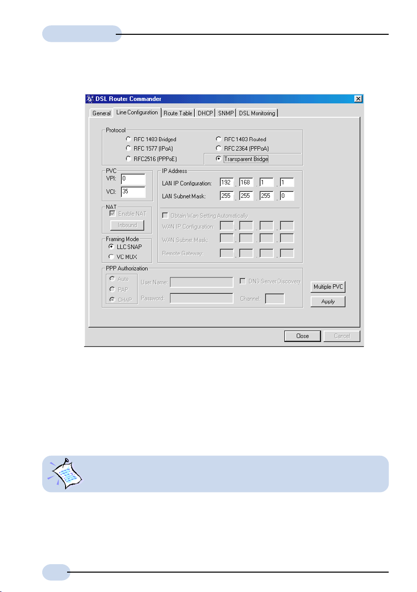
3.1.6 Configuring for Transparent Bridge
i) Select Line Configuration tab. In the Protocol field, click Transparent Bridge.
ii) In the PVC section, enter the VPI and VCI values as assigned by your ADSL Service
Provider.
iii) Select the Framing Mode option as determined by your ADSL Service Provider.
iv) Click Apply for changes to take effect. Upon configuration successful, you will see a
dialog box, 'Configuration Successful' prompted. Click OK.
v) Click Close to save the configurations and exit.
To change the LAN IP address / LAN Subnet Mask at the LAN IP Configuration
/ LAN Subnet Mask field, read the Note on page 14.
28
Page 29

Software Manual
For Multiple PVCs:
vi) For multiple PVCs, click Multiple PVC.
- In the Protocol field, select your desired protocol. (The following instructions
will be based on RFC 1483 Bridged Protocol)
- In the IP Address section, enter the WAN IP Configuration and WAN Subnet
Mask addresses as assigned by your ADSL Service Provider / System
Administrator.
(The WAN IP Configuration must be a unique IP address for different set of
PVC values.)
Depending on your ADSL Service Provider, you may select the option Obtain
Wan Setting Automatically. The WAN IP Configuration and WAN Subnet
Mask fields will be grayed out. The addresses will be allocated by your ADSL
Service Provider's Server automatically.
- In the PVC field, enter the new VPI and VCI values.
- Select the NAT option as determined by your System Administrator. If required,
click Inbound and fill in the data. (See section 3.1.1a - NAT Inbound)
- Select the Framing Mode option as determined by your ADSL Service Provider.
- Click Add. A protocol with the new PVC values will be listed.
(To remove a PVC value, click on the respective protocol and click Remove.)
- Click Apply for changes to take effect. Upon configuration successful, you will
see a dialog box, 'Configuration Successful' prompted. Click OK followed by
Close.
29
Page 30

Software Manual
viii) Click Apply for changes to take effect. Upon configuration successful, you will see a
dialog box, 'Configuration Successful' prompted. Click OK.
ix) Click Close to save the configurations and exit.
30
Page 31

Software Manual
3.2 Route Table
Route Table allows you to set, view or delete a static route or deletes all routes. Check with
your System Administrator for details.
i) Click the Route Table tab.
To add a static IP route, enter all the required information and click Add.
• Label Enter any name for your static route.
• Dest IP Enter the IP Address of the network destination.
• Next Hop Enter the IP address of the Router or gateway to which
packets destined for network destination [Dest IP] should be
sent.
• Netmask Enter the address to indicate network mask of network
destination. (Default is ff.ff.ff.00. For example, 0.0.0.0 is
the default route that will be used if none of the specific
routes defined matches the destination IP.)
31
Page 32

Software Manual
• Cost Enter the value for cost. This refers to the number of hops
counted as the cost of the route, which may affect the
choice of route when the route is competing with routes
acquired from RIP. (But note that using a mixture of RIP and
static routing is not advised.) Default is 1.
• TimeOut Enter the value for timeout (in seconds). This specifies the
length of time before the route entry timeouts. Default of
0 means the route entry will never timeout.
To remove a static IP address, click on the label listed on the table and click Remove.
To remove all the static IP addresses, click Remove All.
ii) Click Close to save the configurations and exit.
32
Page 33

Software Manual
3.3 DHCP
DHCP allows you to add, modify, remove or view the DHCP server to your Router network.
All values are provided by your System Administrator.
DHCP is not applicable for Transparent Bridge configuration.
i) Click the DHCP tab. Click Enable DHCP. Enter the following fields.
• Network ID To identify the network address to which an IP address
belongs.
• Subnet Mask To identify the subnet to which an IP address belongs.
• IP Range Start Refers to the first IP address that Router will assign to a
PC requesting for it.
33
Page 34

Software Manual
• IP Range End Refers to the last IP address that Router will assign to a
PC requesting for it.
DHCP Options
• Gateway IP The IP address of a machine (other Router or server) that
will resolve any unknown destination IP address requested
by Clients.
• Lease Live To specify the number of days how long a DHCP client
(your PCs) can use an assigned IP address before it must
renew its configuration with the DHCP server (Router).
DNS Server
The main purpose for DNS Server is to map host names into Internet addresses
(so call IP address), or vice versa.
If the first DNS server cannot process the translation request, it queries an
upper DNS server, and another one, and so on, until the correct IP address
is returned or no corresponding address for the request can be found.
• Enable DNS Relay Enable this option so that DNS relay will be
informed which DNS Server to contact.
You will only be allowed to enter the IP
address of the Primary DNS Server.
• DNS Server (Primary) The first DNS Server to consult.
• DNS Server (Secondary) The backup DNS Server if the primary one
fails.
ii) Click Remove DHCP to remove the DHCP server from your Router network. Upon
successful removal, you will see a dialog box, 'DHCP Removed Successfully' prompted.
Click OK.
iii) Click Apply for changes to take effect. Upon configuration successful, you will see a
dialog box, 'Configuration Successful' prompted. Click OK.
iv) Click Close to save the configurations and exit.
You need to proceed with section 3.3.1 to configure your Ethernet card for DHCP.
34
Page 35

Software Manual
3.3.1 Configuring Your Ethernet card for DHCP
For Windows® 95 / Windows® 98 / Windows® 98 Second Edition /
Windows® Me
i) From your Windows desktop, right-click on Network Neighborhood. Select Properties.
ii) From the Configuration tab, select TCP/IP-> xxx where xxx refers to the Ethernet card
that is connected to your Router.
Click Properties.
(3Com EtherLink III ISA Ethernet Card is used as an example here. Please select the TCP/IP
protocol that is connected to your Router).
iii) Click the option 'Obtain
an IP address
automatically' and click
OK to save the settings.
When prompted to
restart, click Yes.
35
Page 36

Software Manual
For Windows® XP
i) From your Windows desktop, click Start > All Programs > Accessories >
Communications > Network Connections.
Right-click on the Local Area Connection icon that reflects the model of your Ethernet
Card that is connected to your Router and click Properties.
(This is important especially if you have more than one Local Area Connection icons
displayed.)
ii) Select Internet Protocol (TCP/IP) and click Properties.
(3Com EtherLink III Ethernet Card is
used as an example here.)
iii) Select the option Obtain an IP address automatically and click OK.
Click OK again to close.
36
Page 37

Software Manual
For Windows® 2000
i) From your Windows desktop, right-click on the icon My Network Places. Select
Properties.
At the Network and Dial-up
Connections window, right-
click on the Local Area
Connection icon and select
Properties.
ii) Ensure that the field Connect Using indicates your Ethernet card model.
(This is important especially if you have more than one Local Area Connection icons
displayed at the Network and Dial-up Connections window. Ensure that you have
selected the correct Local Area Connection icon.)
Select Internet Protocol (TCP/IP) and click Properties.
iii) Select the option Obtain
an IP address
automatically and click
OK.
Click OK again to close.
(3Com EtherLink III ISA Ethernet
Card is used as an example
here.)
37
Page 38

Software Manual
3.4 SNMP
SNMP - Simple Network Management Protocol, is used to communicate management
information (MIB or Management Information Base) between the network management
stations (e.g a management software running in your PC) and the agents in the network
elements (e.g your Router).
SNMP communities (used in this case like passwords) can be set with the following table.
Any number of community strings can be set up, each of which can be set to allow either
read-write or read-only access. It also can be usable either from any IP address or only
from a configured management IP address (authorized IP).
i) Click the SNMP tab.
To add an access right or read, enter the required information and click Add.
SNMP Access Right (Write) To have read and write access to SNMP
MIB of your Router.
SNMP Access Right (Read) To have read access only, to SNMP MIB
of your Router.
38
Page 39

Software Manual
Community A community name that corresponds to
the password that you need to provide
when accessing the Router from any
SNMP client.
Authorized IP The IP address of a device (e.g. a PC)
that has the authority to access your
Router.
To remove an access right, select on it and click Remove.
ii) Click Close to save the configurations and exit.
You will not be able to remove ALL Write access password. You need to have
at least one Write access password entered.
39
Page 40

Software Manual
3.5 DSL Monitoring
DSL Monitoring monitors the real-time activities of your Router. It lists down the ADSL
mode, Line Status and ATM Data information. (The following illustrates an example of DSL
Monitoring. What you see on your system will not be exactly the same.)
i) Click the DSL Monitoring tab. The window shows your Router's activities.
ADSL Mode (the options available are models-dependent)
Click to force your Router into detecting the selected mode. Click Reconnect.
Line Status
• Link status Displays the status of your Router. Status are Alive
or Idle.
• ADSL Mode Displays the mode that was selected for your Router.
• Operation Mode Displays the current operating mode of your Router.
• Downstream Refers to the maximum estimated download rate to
your Router.
40
Page 41

Software Manual
• Upstream Refers to the maximum estimated upload rate from
your Router.
ATM Data
Displays the line transfer (packets data) and ATM PVC parameters.
ii) Click Close to save the configurations and exit.
41
Page 42

Glossary
ADSL
ADSL, Asymmetric Digital Subscriber Line, is a broadband communication technology
designed for use on regular phone lines. It has the ability to move data over the phone lines
at speeds up to 140 times faster than the analog modem available today.
CHAP
CHAP, Challenge Handshake Authentication Protocol, is one of the two PPP authentication
protocols, with PAP the other one. Authentication protocol requests information to verify
a valid user. CHAP is a stronger authentication method because it uses encryption and may
repeatedly request verification of the identity of the user any time after the link is established.
Client
Devices and software that request information.
Community
Community names are passwords which are also used by other applications, such as Telnet.
DHCP
DHCP stands for Dynamic Host Configuration Protocol. Every computer on a TCP/IP
network must be given a unique computer name and IP address. DHCP is an industry
standard protocol that specifies methods for dynamic configuration of computers on TCP/
IP networks. It allows centralized configuration of all workstations TCP/IP protocol and IP
address allocation from the server.
After you activate the DHCP server, whenever a network client select dynamic DHCP
configuration option in configuring TCP/IP protocol and IP address, the task of allocation of
IP address will be done dynamically and automatically by the DHCP Server.
DNS
DNS stands for Domain Name Server. The main purpose for DNS is to map host names into
Internet addresses (so call IP address), or vice versa.
If the first DNS server cannot process the translation request, it queries an upstream DSN
server, and another one, and so on, until the correct IP address is returned or no corresponding
address for the request can be found.
DNS Relay
A DNS Relay is a software entity that appears to behave as a DNS server from the point
of view of a DNS resolver, and vice-versa. It forwards DNS queries from a DNS resolver
to a DNS server, and returns responses from the DNS server back to the original DNS
resolver.
42
Page 43

Software Manual
Gateway IP
The IP address of a machine (other Router or server) that will resolve any unknown
destination IP address requested by Clients.
Host
On the Internet, the term host means any computer that has full two-way access to other
computers on the Internet. A host has a specific local or host number that, together with
the network number, forms its unique IP address.
In other contexts, the term generally means a device or program that provides services to
some smaller or less capable device or program.
IP
IP, Internet Protocol, is the method or protocol by which data is sent from one computer to
another on the Internet.
IP Address
A 32-bit binary number that is usually represented as a 4 decimal numbers separated by
dots ".". Each IP address uniquely identifies each host on the Internet.
LAN
Local Area Network. A computer network limited to the immediate area, usually the same
building or floor of a building.
LLC SNAP
LLC SNAP is one of two encapsulation methods used in telecommunication, with VC MUX
the other one. Encapsulation is the inclusion of one data structure within another structure
so that the first data structure is hidden for the time being.
NAT
NAT, Network Address Translation, is designed for IP address simplification and conservation,
as it enables private IP internetworks that use non-registered IP addresses to connect to the
Internet. NAT operates on a Router, usually connecting two networks together, and
translates the private (not globally unique) addresses in the internal network into legal
addresses before packets are forwarded onto another network. NAT has the dual functionality
of security and address conservation, and is typically implemented in remote access
environments.
NAT Inbound
This command enables the user to list or to set up a series of rules for incoming traffic when
NAT is enabled. By default all incoming packets, other that packets arriving in response
to outgoing traffic, will be rejected.
43
Page 44

Software Manual
Network
Any time you connect 2 or more computers together so that they can share resources, you
have a computer network.
Packet
Generic term for a bundle of data, organized in a specific way for transmission over a
network. Packet and datagram are similar in meaning. A protocol similar to TCP, the
User Datagram Protocol (UDP) uses the term datagram.
PAP
PAP, Password Authentication Protocol, is one of the two PPP authentication protocols, with
CHAP the other one. An authentication protocol requests information to verify a valid user.
PAP requests the user's name and password for verification.
Password
A string of characters assigned to you to gain access to a locked system.
PPP
PPP stands for Point to Point Protocol. It normally means: regular phone line, ISDN, xDSL
connections that require their respective point to point modems.
The protocol used to carry TCP/IP traffic to the ISP across modem and ISDN links. PPP
incorporates authentication (username/password checking).
PPPoATM (PPP over ATM)
PPP over ATM - RFC 2364
PPP over ATM (PPPoATM) is the most elegant and simple implementation that provides
encapsulation over a routed ADSL connection.
®
Microsoft provides a PPP over ATM stack in Windows
and Windows
modems such as internal cards and USB devices.
®
2000 and this provides an almost ideal implementation for passive ADSL
98 Second Edition, Windows® Me
PPP
PPPoE (PPP over Ethernet)
PPP over Ethernet (PPPoE) is used in some existing ADSL services. It requires a custom
driver in the users PC, similar manner to Dial-Up Networking. In other words, you will
be dependent on the PPP over Ethernet (PPPoE) client being available for your operating
system platform.
Protocol
In information technology, a protocol is a special set of rules, procedures and conventions
that two end points in a telecommunication connection use when they communicate.
44
Page 45

Software Manual
PVC
PVC, Permanent Virtual Circuit, is an ATM virtual circuit established on top of your ADSL
connection from your Router to your ADSL Service Provider. The call set-up and tear-down
are not visible, which creates the feeling of having a dedicated connection to the Internet.
RFC 2684 (RFC 1483) Bridged or Ethernet Framing
Encapsulation of bridged network data, such as Ethernet frames, in ATM Adaptation Layer
5 (AAL5) Protocol Data Units (PDU).
RFC 2684 (RFC 1483) Routed or IP Framing
Encapsulation and Transmission of routed network data, such as IP datagrams, over ATM
Adaptation Layer 5 (AAL5) Protocol Data Units (PDU).
RFC 2225 (RFC 1577)
Transmission of IP datagrams and ATM Address Resolution Protocol (ATMARP) requests and
replies over ATM Adaptation Layer 5 (AAL5).
RFC 2516
Creation and maintenance of a Point-to-Point-Protocol (PPP) session over an Ethernet link.
RFC 2364
Creation and maintenance of a Point-to-Point-Protocol (PPP) session over an ATM link.
Router
A device that handles the connection between 2 or more networks. Routers spend all their
time looking at the destination addresses of the packets passing through them and deciding
which route to send them on.
SNMP
SNMP stands for Simple Network Management Protocol. SNMP manages the list of SNMP
community names (also used as passwords by other applications, such as telnet) and the
list of SNMP trap destinations.
Static Route
Route that is explicitly configured and entered into the routing table. Static routes take
precedence over routes chosen by dynamic routing protocols.
Subnet Mask
32-bit address mask used in IP to indicate the bits of an IP address that are being used
for the subnet address. Sometimes referred to simply as mask.
45
Page 46

Software Manual
TCP
TCP, Transmission Control Protocol, is a transport protocol used along with the Internet
Protocol (IP) to send data in the form of message units between computers over the Internet.
While IP takes care of handling the actual delivery of the data, TCP takes care of keeping
track of the packets and provide error recovery mechanism.
TCP/IP
See TCP.
Telnet
Telnet is the way you can access a remote computer, provided you have given access to it.
More technically, Telnet is a user command and an underlying TCP/IP protocol for accessing
remote computers. With Telnet, you log on as a regular user with whatever privileges you
may have been granted to the specific application and data on that computer.
Transparent Bridge
Joining two or more bridged network segments (such as Ethernet) running on different
physical media.
UDP
User Datagram Protocol. UDP is a stateless protocol in that it makes no provision for
acknowledgement of packets received.
VPI/VCI
The ATM Virtual Path Identifier (VPI) and Virtual Channel Identifier (VCI) uniquely identify
a virtual circuit on an ATM link, such as PVC. An ATM switch (or other device incorporating
ATM switching capability like a DSLAM) can be configured to take data from one VPI/VCI
on an incoming link and map it to another VPI/VCI on an outgoing link. This configuration
defines the route through the ATM switch. Note that this means that a particular data
connection may be given many different VPI/VCI addresses as it passes through the
network.
WAN
Wide Area Network. Any Internet or network that covers an area larger than a single
building or campus.
46
Page 47

Index
A
ADSL Mode 40
ATM Da t a 41
Authentication 5
Authorized IP 39
C
Channel 5
communities 38
Community 39
Configuration 14, 35
Cost 32
D
Default WAN Gateway 5
Dest IP 31
DHCP 11, 33, 35
DHCP Options 34
DNS Server 34
DNS Server (Primary) 34
DNS Server (Secondary) 34
End 34
Gateway IP 34
IP Range Start 33
Lease Live 34
Network ID 33
Subnet Mask 33
DNS Server 34
DNS Relay 34
DNS Server (Primary) 5, 34
DNS Server (Secondary) 5, 34
DNS Server Discovery 24, 25
Downstream 40
DSL Monitoring Application 11, 40
ADSL Mode 40
ATM Da t a 41
Downstream 40
Link status 40
Upstream 41
DSL Router Commander 4
E
End 34
Ethernet Card 35
Configuration 14, 35
Configuring Your Ethernet card for DHCP 35
F
Framing
Mode 5, 13, 18, 21, 22, 25, 26, 28, 29
G
Gateway IP 34
H
Host IP Address 19
I
Inbound 13, 18, 19, 21, 22, 23, 24, 25, 26, 29
Host IP Address 19
New IP Addr 19
Por t 19
Por t/Proto 19
Protocol 19
IP Address 13, 18, 21, 22, 23, 24, 26, 29
IP Range Start 33
L
Label 31
LAN IP Address 20, 22, 24, 25, 29
LAN IP address 6, 20
LAN Subnet Mask 6, 20, 22, 24, 25, 29
Lease Live 34
Link status 40
N
NAT 6, 8, 13, 18, 19, 21, 22, 23, 24, 25, 26, 29
Netmask 31
Network ID 33
New IP Addr 19
Next Hop 31
47
Page 48

Software Manual
P
Password 4, 5, 24, 25
Port 19
Port/Proto 19
PPP Authorization 24, 25
Protocol 19
PVC 13, 18, 21, 22, 23, 24, 25, 26, 28, 29
R
Remote Gateway 6
RFC 1483 Bridged 12, 13, 45
RFC 1483 Routed 12, 21, 45
RFC 1577 5, 12, 23, 45
RFC 2225 5, 12, 23, 24, 45
RFC 2364 5, 12, 25, 45
RFC 2516 5, 12, 24, 45
RFC 2684 Bridged 12, 13, 23, 24, 45
RFC 2684 Routed 12, 21, 45
Route Table 11, 31
Cost 32
Dest IP 31
Label 31
Netmask 31
Next Hop 31
TimeOut 32
Router IP Address 4
S
SNMP 11, 38
Authorized IP 39
Community 39
SNMP Access Right (Read) 38
SNMP Access Right (Write) 38
Subnet Mask 33
T
TimeOut 32
Transparent Bridge 12, 28, 33
Configuring for Transparent Bridge 28
U
Upstream 41
User Name 5, 24, 25
V
VCI 5, 13, 21, 23, 24, 25, 28
VPI 5, 13, 21, 23, 24, 25, 28
W
WAN IP 5
WAN IP Configura-
tion 13, 18, 22, 23, 26, 29
WAN Subnet
Mask 5, 13, 18, 22, 23, 26, 29
48
 Loading...